Note: Descriptions are shown in the official language in which they were submitted.
..~ ~ r ii ~~ .~
coo-17
VALVE FOR A TAP iDF A C~JMPR1~SSED OR T.IQUIFIED CAS
CYTaIPIDER~AND 'i'AP PROVTDED 4~IIri'FI SilCH A VAhVE
y The present .invewtion a~elates to a valve for a
tap of a compressed or liquefied gas cylinder, which
valve is intended to be fitted on an inlet pipe of -the
tap, comprising a casing with at least one lateral
opening which can be shut off by a plug provided with a
passage for gas and which can be displaced, under 'the
influence of resilient means, between a position in which
the openings are shut off and an open position counter to
the action of the said resilient means and under the
influence of the pressure of the filling gas, and a level
valve activated lay, a means for detecting the filling
level, and at least one orifice establishing communica-
~tion between the inside of the casing and the inlet pipe,
on the one hand, and the inside of the cylinder, on the
other hand> The invention also relates to a tap provided
with such a valve.
A tap provided with such a valve is known and is
described in greater detail in French Patent Application
No> 9,116,025> This tap is mots particularly intended for
gas cylinders which can be refilled by the user himself
in a gas supply centre. To fill such a cylinder correctly
in accordance with safety regulations, the cylinder must
not be filled completely in order to preserve, above the
liquefied gas, a gaseous zone which can act as a buffer,
in the event of the cylinder being expased to a heat
source, and which can be released via a safety valve
which must therefore obligatorily be situated in this
gaseous zone. To this end, the tap described in the
abovementioned patent application comprises a 'two-way
valve which enables the cylinder to be filled and emptied
and which is combined with a level valve, which whilst
the cylinder is being filled, automatically closes the
two~way valve when the gas level in 'the cylinder reaches
a predetermined threshold>
During the filling operation, by closing the tap
after the level. valve has been closed by the action of
,,., p
r
6~ n '~) ':~
- 2 -
the float, a certain quantity of lic~u.id gas remains
trapped inside the valve and the inlet pipe of the tap.
Now, seeing ~tha~t this trapped gas is in the liquid phase
and is situated beyond the field of action of the safety
valve, there is a danger of an ~:xplosion in the event of
overheating. In order to avoid such a danger, an orifice
has been provided in the wall of the casing of the valve
which allows the liquid gas to flow into the cylinder
after the tap has been closed, and thus enables the
safety valve to perform its ~:unetions as fax as the
inside of the chambex and of the inlet pipe. The cross-
sectian of this orifice must be less 'than the cross-
section of the passage in the plug in order to make it
possible to build up a sufficient pressure, after the
level valve has been closed, in the chamber to cause the
plug to slide into the position closing the lateral
openings. Despite this oxifice being small, it neverthe-
less has a negative influence on the speed of closure of
the valve when the filling threshold is reached in that
it delays the pressurization of the chamber within the
casing.
Furtheranore, a sensible user could continue the
filling process even after the level valve has been
closed, given that communication remains between the
inlet pipe and the inside of the cylinder via this
orifice. Admittedly, such an excessive filling would be
very slow because of the limited throughput through the
small cross~section of the orifice, however, seeing that
the possibility exists, it is not out of the question for
~0 a cylinder to be filled beyond the safety threshold
tolerated by the level detector and its closure valve.
The obaect of the present invention is to provide
a valve of the abovementioned type which closes more
quickly when the filling threshold is reached and ~,rhich
excludes all possibility of continuing the filling of the
cylinder after the valve has closed.
To achieve this aim, the invention provides a
valve of the type described in the pre-characterizing
clause, which is characterized in that the said orifice
CA 02127641 2001-07-06
- 3 -
is associated with resilient means resisting the maximum
filling pressure in order to ensure the leaktight closure
of the orifice and which yield at a pressure greater than
the filling pressure in order to free the orifice.
According to the most simple embodiment, the
said resilient means consist of an O-ring made from
resilient rubber arranged in a groove around the casing
of the valve, into which groove the orifice or orifices
opens or open.
The invention also provides a tap which is
provided with a valve as defined above.
According to a variant embodiment of the tap
provided by the invention, the orifice and the said
resilient means are not situated in the wall of the
casing of the valve but in the wall of the inlet duct.
In any case, given that the said resilient
means resist the filling pressure, they no longer permit
the continuation of the filling through the orifices in
question once the level valve is closed. They do,
however, continue to fulfil their safety functions given
that they yield under the action of an excessive pressure
greater than the filling pressure to enable the gases
contained in the valve and the inlet pipe to flow into
the cylinder.
Therefore, in accordance with the present
invention, there is provided a v aloe for a tap of a
compressed or liquefied gas cylinder, which valve is
intended to be fitted on an inlet pipe of the tap,
CA 02127641 2001-07-06
- 3a -
comprising a casing with at least one lateral opening
which can be shut off by a plug provided with a passage
for gas and which can be displaced, under the influence
of resilient means, between a position in which the
openings are shut off and an open position counter to the
action of the said resilient means and under the
influence of the pressure of the filling gas, a level
valve activated by a level-detection means for detecting
the filling level, and at least one orifice establishing
communication between the inside of the casing and the
inlet pipe, on the one hand, and the inside of the
cylinder, on the other hand, wherein the said orifice is
associated with resilient means resisting the maximum
filling pressure in order to ensure the leaktight closure
of the orifice and which yield at a pressure greater than
the filling pressure in order to free the orifice.
Also in accordance with the present invention,
there is provided a tap for compressed or liquefied
gases, comprising a tap body designed to be fitted on a
gas cylinder and containing a closure member at the
intersection of an inlet pipe and an outlet pipe, a means
for operating the closure member, a safety valve, a first
valve comprising a casing with at least one lateral
opening which can be shut off by a plug provided with a
passage for gas and which can be displaced between a
position in which the openings are shut off under the
influence of a resilient means and an open position
counter to the action of the resilient means under the
CA 02127641 2001-07-06
- 3b -
effect of the pressure of the filling gas, a second valve
activated by a level-detection means for detecting the
filling level, and at least one orifice establishing
communication between the inside of the casing and the
inlet pipe, on the one hand, and the inside of the
cylinder, on the other hand, wherein the said orifice is
associated with resilient means resisting the maximum
filling pressure in order to ensure the leaktight closure
of the orifice and which yield at a pressure greater than
the filling pressure in order to free the orifice.
Still in accordance with the present invention,
there is provided a t wo-way valve for a tap of a gas
cylinder, which valve is intended to be fitted on a
selectively operable inlet pipe of the tap, said two-way
valve permitting both filling and draining of the gas
cylinder and comprising a casing with at least one
lateral opening which can be sealed off by a sealing
device provided with a passage for gas, resiliently
yieldable means for displacing the sealing device to a
position of obstruction of the openings and for
permitting the sealing device to move to a position of
opening against the action of the resiliently yieldable
means through the effect of the pressure of the filling
gas, a level-controlling valve movable between open and
closed positions and operable, when in said open
position, to permit gas to flow between the gas cylinder
and the passage, and detecting means for detecting the
filling level in the gas cylinder and for actuating the
CA 02127641 2001-07-06
- 3c -
level-controlling valve in response to such level, said
level-controlling valve, when not held in an open
position by said detecting means, being operable by the
pressure of the gas in the cylinder when the pipe is
open, at least one orifice being disposed in at least one
of a wall portion of the inlet pipe and a wall portion of
the casing for establishing communication between the
inside of the casing and the inlet pipe, on the one hand,
and the inside of the cylinder, on the other hand, said
orifice being associated with resilient vent means which
resist the maximum filling pressure in order to ensure
the leak tight closure of the orifice and which yield at
a pressure greater than the maximum filling pressure in
order to open the orifice to prevent pressure from
building up within either one of the inlet pipe and the
casing.
Still further in accordance with the present
invention, there is provided a t ap for gas and
comprising a tap body designed to be fitted on a gas
cylinder and enclosing a closure member at the
intersection of an inlet pipe and of an outlet pipe,
means for manoeuvring the closure member, a safety valve,
the inlet pipe communicating, on the side opposite the
closure member, with a two-way valve permitting both
filling and draining of the gas cylinder, said two-way
valve comprising a casing with at least one lateral
opening which can be sealed off by a sealing device
provided with a passage for gas, resiliently yieldable
CA 02127641 2001-07-06
- 3d -
means for displacing the sealing device to a position of
obstruction of the openings and for permitting the
sealing device to move to a position of opening against
the action of the resiliently yieldable means through the
effect of the pressure of the filling gas, a
level-controlling valve movable between open and closed
positions and operable, when in said open position, to
permit gas to flow between the gas cylinder and the
passage, detecting means for detecting the filling level
in the gas cylinder and for actuating the
level-controlling valve in response to such level, said
level-controlling valve, when not held in an open
position by said detecting means, being operable by the
pressure of the gas in the cylinder when the closure
member is open, at least one orifice being disposed in at
least one of a wall portion of the inlet pipe and a wall
portion of the casing for establishing communication
between the inside of the casing and the inlet pipe, on
the one hand, and the inside of the cylinder, on the
other hand, said orifice being associated with resilient
vent means which resist the maximum filling pressure in
order to ensure the leak tight closure of the orifice and
which yield at a pressure greater than the filling
pressure in order to open the orifice to prevent pressure
from building up within either one of the inlet pipe and
the casing.
Other features of the invention will become
apparent from an advantageous embodiment presented below
CA 02127641 2001-07-06
- 3e -
by way of example, with reference to the single figure
which diagrammatically illustrates a vertical section
through a tap and a two-way valve according to the
present invention.
The structure and operation of the known tap
will now be summarized briefly with reference to the
figure. The reader should refer to French Patent
Application No. 9,116,025 for further details.
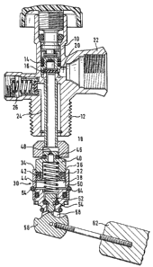
The tap illustrated in this figure comprises a
metal body 10, for example made from brass, the lower
part of which is provided with a thread 12 allowing the
tap to be screwed onto a gas cylinder. The tap comprises
a closure member 14 with a seal 16 at the intersection of
4W .~. rv~ ~n VJ 1 .L.
.. 4
an axial inlet duct 18 communicating with the inside of
the cylinder, and a radial outlet duct 20 communicating
with a connecting socket 22 which can be connected to a
use circuit. The closure member 14 is activated manually
using a lever or an operating wheel.
A passage 24 which establishes communication
between the inside of the cylinder and a safety valve 26
is situated around the inlet duct 18. This valve allows
gases to escape in the event of an abnormal excess
pressure of the gas inside the cylinder. To this end, the
passage 24 must obligatorily be in the gaseous zone, i.e.
the cylinder cannot be filled up to the body 10 of the
tap.
The inlet duct 18 is connected, inside the
cylinder, to a two-way valve 30 which enables the gas
cylinder to be both filled and emptied. This valve 30
comprises a casing 32 with two lateral openings 34 and
36. Inside this casing 32 is situated a cylindrical
chamber 38 containing a plug 40 in the form of a piston
which can slide axially and the sealing contact of which
with the casing 32 is ensured by an ~-ring 42. This
piston 40 is subject to the action of a spring 44 which
tends to maintain the piston 40 in the position in the
figure, in which its head is held, via a seal 46, leak-
tightly against the edge of the casing 32 in order to
isolate the two lateral openings 34, 36 of the inlet duct
18. The chamber 38 communicates with 'the inlet duct 18
via an axial passage 48 through the piston 40.
The lower part of the valve 30 consists of the
actual level valve 52. This valve 52 can slide axially
between an open position freeing an annular passage for
the gases between the casing 32 and the periphery of the
valve 52 and a closed position in which the valve 52 is
held leaktightly via a seal 54 against the Lower part of
the casing 32, forming the seat for this valve 52.
The valve 52 comprises a rounded foot which
interacts with a cam 56 mounted pivotably in a clevis
joint 58 of the casing 32. This cam 56 has a profiled
contour designed so as to cause the valve 52 to move
~.. ~ '.~ l (.h ~~ .~1.
- 5 -
axially by its foot sliding along this profiled contour.
The cam 56 is caused to pivot by a float: 62 as the level
of the liquified gas in the cylinder rises and falls.
When the cylinder is empty, the float 62 is in a
lower position, whilst the level valve 52 is in a raised
and open position under the influence of the cam 56. The
connecting socket 22 is connected to a gas source with a
view to filling the cylinder, and the closure member 14
is opened by the operating wheel. The gas enters under
pressure through the inlet pipe 18 and, as a result of
its pressure, depresses the pa.ston 40 counter to the
action of the spring 44 as far as the bottom of the
chamber 38, thus freeing the two lateral openings 34 and
36 for the gas to pass into the cylinder.
The gas also enters 'through the passage 48 of the
piston 40 and flows around the valve 52, in the open
position, into the cylinder. A buildaup of pressure in
the chamber 38 must be prevented, as pressurisation of
said chamber 38 would be liable to cause the piston 40 to
rise up and close the two lateral openings 34 and 36. To
this end, the cross-section of the annular passage for
gas flow around the valve 52 must be greater than the
cross-section of the passage 48 in order to prevent the
gas in the chamber 38 from being compressed.
When the float 62 pivots, as a result of the
cylinder being filled, in an anticlockwise direction
beyond the angular position in the figure, the cam 56
releases the valve 52 to fall onto the seal 54 under the
pressure of the filling gas. As soon as the valve 52 is
closed, tlae increase in the pressure inside the chamber
38, combined with the action of the spring 44, causes the
piston 40 to rise up and close tine passage fox the gas
through the openings 34 and 36 and thus terminate the
filling process.
In order to use the gas contained in the cylin-
der, you simply need to open the tap using its operating
wheel. When the cylinder is completely full and the level
valve 52 is closed, the flow of the gas from the chamber
38 and from the inlet pipe 18 lowers the pressure in this
t w'~ ~a
- 6 -
chamber 38 and allows the pressure of the gas in tkie
cylinder to lift the level valve 52 into an open posi-
tion. The gas can then flow around the valve 52 and
escape through the passage 48 of the piston 40. Once the
level of the liquid gas in the cylinder has fallen as far
as'the position of the float 62 in the figure, the valve
52 is held open by the circular cross-section of the
profiled contour of the cam 56 and there is nothing to
prevent the flow of gas thxough the valve 30 each time
the tap is opened.
The feature of this tap is consequently that it
stops the filling operation automatically withowt requir-
ing the attention or intervention of the user, and does
so by means of a two-way valve enabling the cylinder to
be emptied via the level valve and in accordance with the
safety regulations which dictate 'that the entire gaseous
zone must be situated within the field of action of the
safety valve.
In order to prevent liquid gases from being
trapped in the duct 18 and in the chamber 38 after the
level valve has been closed, which gases would be situ
ated beyond the zone of action of the safety valve 26,
one or more safety orifices 50 have been provided in the
wall of the casing 32 establishing communication between
the inside of the cylinder arid the inside of the chamber
38 and of the duct l8.
However, in order to avoid the disadvantages and
risks of such orifices, as described in the introduction,
the present invention proposes to associate the orifice
50 with means which keep it closed until the maximum
filling pressure is reached.
In their most simple embodiment, these means
consist of an O-ring 64 made from resilient rubber which
is housed in a groove around the casing 32, into which
groove the orifice 50 opens. Assuming that the maximum
filling pressure when the level valve closes is 12 x 10s
Pa, the seal ~64 is, for example, designed to resist a
pressure of 26 x 105 Pa. The filling pressure is there-
fore not able to cause the seal 64 to yield, opening the
,; -~ ,", ~., r
.~ HI ~ 4~ ~.~
- 7 -
orifice or orifices 50, with the result that it is
impossible for filling to take place through said
orifices after the level valve 52 has c:Losed.
However, if, for example following raeating yap,
the pressure in the chamber 38 and in the duct 18 exceeds
the threshold 16 x 105 Pa, the resilient seal frees the
orifice 50 and releases the excess pressure into the
cylinder.
Given that the orifice 50 remains closed during
the filling phase, the pressurisation of the chamber 38
when the valve 52 closes takes place more quicJcly, so the
response of the valve 30 to the: action of the float is
also quicker.
Instead of providing a resilient seal 6~, it is
also possible to associate the orifice 50 with a small
valve subject to the action of a calibrated spring of the
safety valve type like the valve 26.
Moreover, the safety orifice or orifices 50 and
their resilient closure means do not necessarily have to
be situated in the wall of the casing. Positioning them
in the wall of the inlet pipe 18 provides the same
results.
Correct operation of the known valve required a
cross-section of the orifice 50 which was less than that
of the axial passage 48. This condition no longer exists
in the valve proposed by the present invention, given
that the orifice 50 is always closed during normal
operation.
Lastly, it should be noted that the invention is
not limited to a valve of the two-way type as described
above by way of example wi~tka reference to the figure. It
can just as easily be applied to a valve which is only
used to fill the cylinder, i.e. gas is extracted using a
different tap.