Note: Descriptions are shown in the official language in which they were submitted.
- ~ 212773~
"Method and apparatus for joining two edges of a
knitted tubular article upon completion thereof~
FIELD OF T~13 INVE~TION
The present invention refers to a method and
apparatus for operating the union of the two edges
of a knitted tubular article, such as the linklng
of the sock toe upon completion of the knitting of
the article.
BACKROUND OF THE INVENTIO~
It is known that socks are manufactured with
circular machines having one or two needle
cylinders, the knitting starting from the elastic
hem and fini6ching at the toe side which i6 left
open to be closed afterwards by suitable seamer-
linker machines. More specifically, it is known
that after the formation of the necessary ranks for
the sock toe, a number of waste ranks of a so-
called "unthreading" edge is formed, usually of
shaved knit one centimeter high, to avoid ladders
during the seaming of the toe. Depending on the
type of machine being used, the socks are produced:
a) one after the other. In this case, the last
unthreading rank of the toe is connected to the
first rank of the elasic hem of the next sock
through a resistant~ smooth and well visible thread
212773~
which is worked with a feeding unit other than that
for the elastic hem, and which is to be manually
removed to separate one sock from the other prior
to the seaming of the toe;
b~ one separate from the other. This procedure is
used mostly in the single- or two-cylinder circular
machines which are provided with an automatic
device for the separation of the manufactured
socks.
Afterwards, each sock must be turned inside out
to allow for the seaming on the reverse side
thereof. Then, the toe is closed by removing said
waste edge and sewing the stitches of the last
semirank of the back of the foot together with the
stitches of the last semirank of the sole.
However, seaming the toe of the socks outside
the machine which make them brings about an
i.ncrease in the time and cost of production, mainly
as a consequence of the numerous intermediate
operations to be carried out after the completion
of the knitting and before the very seaming of the
toe, intermediate operations which include, for
example, the removal of the socks and the transfer
thereof to the relevant stocking stores where they
are selected according to their colour and/or size.
212773~
All this implies, in fact, relying on skilled
personnel who carry out and supervise these
operations, and the provision of sufficiently large
premisis for siting the machines and selectively
storing the socks. Moreover, in case of large
numbers of thus formed socks, the amount of yarn
which is wasted in the manufacturing of the socks
and the subsequent removal of the said waste edge,
results significantly high and, therefore, the
relevant cost is economically ineffective and
heavily detrimental to the yield of the traditional
manufacturing plants.
The Italian patent application No. FI92A194
discloses a method for seaming two front edges of a
knitted tubular article, especially a sock, and
comprising the step of manufacturing a knitted
tubular article, by means of a one-cylinder
circular machine, by starting from the elastic hem
and finishing on the side of the toe which is left
open, the method further comprising the following
operating steps: - lifting a predetermined number
of needles of a first semirank, together with the
respective stitches, up to a predetermined level:
the term semirank referring to a plurality of
adjacent stitches belonging to an edge of the
2127734
article toe; - lifting a predetermined number of
needles of a second semiran~, together with the
respective stitches thereof, to the same level as
those of the first semirank; - removing the
stitches of the first semirank, lowering the
corresponding needles and transferring said
stitches, through a 180 overturning thereof about
a horizontal diametral axis of the needles
cylinder, so that each thus overturned stitch will
fit the relevant needle of the second semirank;
releasing the stitches of the first semirank from
the relevant transfer means and moving the thus
superimposed pairs of stitches to a level suitable
for the linking thereof; - rotating the needles
cylinder intermittently to insert step-by-step a
linking needle into a pair of thus disposed
stitches by supplying it, without solution of
continuity, with the thread used for knitting the
article, and then removing it to form a hook-up
plain-chain stitch.
The same document disclo6es an apparatus for
carrying out the above method, which comprises: -
cam means for vertically moving a predetermined
number of needles of a first and second semiranks
of stitches of the toe of the article in the course
~ 2~2773'~
of ~ormation, which means are in operating
condition when the knitting cams of the circular
machine are in inoperative condition, and vice
versa; - means for remo~ing the stitches of said
first semirank and overturning them through 180
about a diametral horizontal axis of the needles
cylinder, with a pair of spikes for each stitch and
at least a corresponding opening and respeGtively
closing peg, each of which is slidingly housed
within a corresponding slots of a semicircular
sector: said sector being mounted for a 180
displacement in both directions about a diametral
horizontal axis of the needles cylinder, in a
position above the sinkers of the machine; - means
for making said semicircular sector solid to the
needles cylinder, with a radial shutter sliding
between two positions of locking and respectively
releaæing the æector with respect to the needles
cylinder, but in a constant and preæet spatial
location; - fork means for locking the sinker
housing during the horizontal rotation of said
semicircular sector in conjunction with the needles
cylinder, said fork means being activated by
corresponding cam means solid to the support of
said semicircular sector; - means for linking the
212773~
paired and superimposed stitches being loaded on
the needles of the second semirank by means of a
linking bearded needle, with a crochet operatively
associated to said needle and located on the
opposite side thereof with respect to the stitchea,
and with a wheel or skid for pressing down the
fabric and holding the stitches in linking attitude
during the linking operation. The said wheel or
skid being located on the same side of the linking
needle with respect to the knitting needles. The
whole of the above said means being disposed on top
and sideways of the needles cylinder.
The above operating method, although making it
possible to provide a finished product of good
quality, implies the need of leaving the knitting
needles inserted, the same needles supportin~ the
stitches of the article during the linking
operation inside the tuck loops which constitute
the seam stitches, 80 that the hook-up line joining
the edges of the article results slightly expanded.
The shed for sewing said edges results the same as
the knitting one, instead of being smaller as
necessary to achieve a closer and more elastic
seaming and make, therefore, a better quality
article. Besides, the apparatus for implementing
~ 2127734
the known method is of remarkable constructional
complexity, especially in relation to the large
number of elements disposed in correspondence of
the knitting head of the circular machine. This
implies, above all, the need of providing a strict
procedure for the integration and coordination of
the apparatus with the circular machine which makes
the article, as well as a reduced level of
modularity, that is, a substantially reduced
possibility of adding further elements able to
improve the quality of the product as far as the
knitting and/or final hook-up is concerned and,
besides, greatly limiting the access to the
individual components of the linking device. All
this at the expense of simplicity and cost of
intervention for assemblying and/or up-keeping the
circular machine and/or the same apparatus for the
linking of the toe. Moreover, the circular machines
for the knitting of the article must be properly
suited, from the architectonic, structural-
mechanical and operational point of view, to the
specific disposition of the means provided to carry
out the above toe-closing method. In view of the
numerous constructional and functional differences
which differentiate the various circular machines
~ 2~773~
known at present, this represents a drawback owing
to the limitation of interchangeability degree of
the apparatus which, accordingly, must be designed
to meet the specific requirements of the knitting
machine it is to make part of.
SUMMARY AND ORJECTS OF THE INVENTION
The main object of the present invention i8 to
overcome the drawbacks derived from the traditional
operating procedures and provide a method and an
àutomatic apparatus, for joining the edges of a
knitted tubular article, which make it possible to
obtain a finished product of superior quality and,
at the same time, a significant functional
simplification as far as the construction and
maintanance of the linking apparatus and knitting
machine are concerned.
This result has been achieved, according to the
invention, by adopting an operating method
comprising the initial steps of manufacturing a
knitted tubular article such as a sock, starting
from the elastic hem and finishing on the side of
the toe which is left open, by means of single-
cylinder circular machine, and disposing the last-
to-form stitches of a first semirank on the
knitting needles of a second semirank of stitches
2~ 2773~ ~
through a 180 overturning thereof about a
diametral axis of the needles cylinder, the latter
being operated by corresponding stitches~
transferring means so that the pairs of stitches of
the first and second semiranks will r0sult retained
on the needles of the second semirank, and which
method, according to the invention, comprises the
further operating steps:
- lowering the needles of the second semirank, with
the sinkers being open, so as to move the stitches
of the first and second semiranks to a level
beneath that of the sinkers nib of the machine;
- lifting the needles of the second semirank, with
the sinkers being closed, so that the corresponding
pairs of stitches of the first and second semiranks
will result retained by the sinkers at a
predetermined position relative to the stem of the
respective needles;
- lifting farther the needles of the second
semirank until all the corresponding pairs of
stitches will reach the operating level of the
transfer means of the first semirank, so as to have
the stitches retained by said means;
- lowering the needles of the second semirank so as
to allow the article to have the stitches of the
- --` 2127~34
first and second semiranks removed from said
transfer means, that is, to clear the article of
the knitting needles;
- transferring the article, with the thus retained
stitches, so as to locate it at a predetermined
distance form the knitting cylinder;
- disposing the thus transferred stitches so as to
have them angularly equidistant, with a circular
pitch that can be varied, that is, selected
according to the required degree of hook-up
fineness;
- linking the corresponding pairs of stitches thus
disposed, by means of a linking needle, to form a
chain and, upon completion of the hook-up, making
one or more knots for closing the chain;
- cutting the hook-up thread;
- releasing the thus joined pairs of stitches of
the first and second semiranks, to allow the
article to be removed in its final, right-side out
condition.
It may be useful to point out that a stitch is
intended in its retained position when it i8 fitted
on a latch needle and at a level between the needle
beard hook and the free end of the latch, the
latter being in its fully open condition.
12
;} ~
~ 2~2773~
Advantageously, according to the invention,
provision is made for inserting the terminal length
of the linking thread, that is the one for making
the hook-up, inside the article, after having
executed the knots for the closing of the chain.
Moreover, the linking thread may be either the same
as used for the knitting of the article, without
solution of continuity, or a different thread as
fed by a corresponding reel other than that
supplying the knitting thread.
As far as the apparatus for implementing said
method is concerned, it comprises:
- cam means for operating the lifting and
respectively the lowering of a predetermined number
of needles of a first and second semiranks of
stitches, which means are in operative condition
when the knitting cams are inoperative, and vice
versa;
- means for removing the stitches of said first
semirank and overturning them through 180 about a
diametral axis of the needles cylinder and,
~esides, for removing the pairs of corresponding
stitches from the needles of the second semirank,
with a pair of spikes for each stitch, respectively
pair of corresponding stitches, and at least a
13
L;~
2~2773~
corresponding opening respectively closing peg,
which peys are slidingly received within
corresponding slots of a semicircular sector: said
sector being rotatively mounted to perform a 180
angular displacement thereof in both directions
about a diametral axis of the needles cylinder at a
position overlying the sinkers of the machine
producing the article and supported by members
allowing the transfer thereof from the knitting
station to a station for linking the article toe;
- cam means, located in correspondence of the
knitting station, for driving said spikes and
respectively pegs within the corresponding slots of
the oscillating sector;
- cam means for operating the 180 overturning in
both directions of said semicircular sector about a
diametral axis of the needles cylinder;
~ cam means for maintaining the sinker housing of
the circular machine at a predetermined and
constant angular position;
- an actuation cylinder for operating the transfer
of the member supporting the said semicircular
sector from the knitting station to the station for
linking the article toe;
- cam means, in correspondence of the knitting
14
212773~
station, for driving said spikes and respectively
pegs during the steps of presetting the stitches
for the linking thereof and of expelling the
finished product;
- a seamer--linker to carry out the seaming-linking
of pairs of corresponding stitches and making the
knots to close said seaming-linking line;
- means for finally cutting the seaming-linking
thread;
- means for holding the end of the linking thread
a'ter the cutting thereof.
Advantageously, according to the invention,
means are provided for inserting the terminal end
or tail of the linking thread, which results joined
to the article, inside the latter.
The advantageæ obtainable from the present
invention lie essentially in the fact that it is
possible to perform the closing of the toe of a
knitted tubular article, immediately donstream of
the machine producing said article, and in a fully
automatic way, thereby signficantly reducing the
time and cost of manufacturing; that some steps of
the traditional process for closing the toe of the
knitted tubular articles - such as the formation of
the unthreading and relevant waste material, the
.,
2~2773~
transfer of the articles from the circular machine
to the stocking stores or to the seamer-linker
machines, the turning inside out thereof, the
seaming of the toe and the subsequent turni.ng
right-side out thereof - are completely eliminated;
that it is possible to automatically performing the
linking of the article edges out of the knitting
station and placing the linking means at a
predetermined distance therefrom yet providing a
single production unit; that it is possible to
achieve a high degree of accessibility to the means
of the knitting station and those of the linking
station, as well as to the means for the transfer
of the article from one to the other of said
stations, which results particulraly advantageous
upon the assembly of the production unit and during
the steps of maintainance and regulation of the
various actuation means; that it is possîble,
during the linking of one article, to
simultaneously operate the knitting of the next
one, which brings about a remarkable reduction of
the machine dwell times and an increase of the
output thereof in terms of finished product; that
it is possible to carry out said linking also using
the same thread as used for the knitting of the
16
11 2773~
article, without solution of continuity, so as to
avoid the cyclic "starting-up" of the hook-up, that
is, the formation of the initial stitch of same
hook-up, and the presence of the so-called tail of
the linking thread; that it is possible to operate
said linking with any stitch suited for making
knitting articles, such as the ~plain chain~ stitch
which exhibits an excellent elasticity and allows
using most of the threads available on the market;
that it is possible to perform the closing of the
sock toe with seams of various types of contour,
such as the "fish mouth~ or shark mouth", ln
addition to those of traditional type; that it
possible to carry out said linking on the side of
either the back or sole of a sock by simply
providing a pocket of fabric on one side or the
other of the article with respect to its heel; that
upon completion of the linking of the toe, the
article results in its final right-side out; that
the finished product if of the best quality, from
both the aesthetical and functional point of view,
since also the seam is kn.itted and joints the two
edges of the toe without any increase in its
thickness; that an apparatus according to the
invention is of high reliability even after a
2~2~73'1
prolonged use thereof; that any traditional
circular machine can be provided with said
apparatus without radically altering its basic
functional and constructional structure.
BRIEF DESCRIPTION OF T~E DRAWINGS
These and other advantages and characteristics
of the invention will be best understood by anyone
skilled in the art from a reading of the following
description in conjunction with the attached
drawings given as a practical exemplification of
the invention, but not to be considered in a
limitative sense, wherein:
- Fig. lA is a schematical view in longitudinal
section showing an apparatus, according to a first
embodiment of the invention, upon the beginning of
the cycle for the closing of the toe of the tubular
article;
- Fig. lB is a plan view of the means for the
tranPfer of the article from the knitting station
to the linking station, in the apparatus of Fig.
lA;
- Fig. lC shows in detail the cams and relevant
drive means for operating the overturning of the
semicircular sector of the apparatus of Fig. lA;
- Fig. lD is a side view of the means of Fig. lC;
18
212773~
- Fig. 2A shows schematically the means of Fig. lB,
with the linking means in stand-by condition;
- Fig. 2B shows the means of Fig. lB as detached
from the knitting head of the machine, with the
linking means in stand-by condition;
- Fig. 2C shows the means of Fig. lB during the
linking of the article toe, with the linking means
in active condition;
- Fig. 2D shows schematically the step of Fig. 2A
with the suction hose of the knitting machine in
normal, that is, lowered position;
- Fig. 2E shows the step of Fig. 2B with the
suction hose in lifted posi.tion;
~ Fig. 3A is a side view of an apparatus as in Fig.
lA, according to an alternative embodiment;
- Fig. 3B is a plan view showing the oscillating
semicircolar sector, the relevant support member,
the corresponding overturning means and the means
for keeping the sinker housing in a fixed spatial
position;
Fig. 3C is a plan view of the means for the
transfer of the article from the knitting to the
linking station in the apparatus of Fig. 3A;
- Fig. 3D is aview showing in detail the means for
connecting the sinker housing with the machine,
lg
: ` ^` 212773~
upon the initial step of their motion;
- Fig. 3E shows in detail the means of Fig. 3D upon
an intermediate step of their motion;
- Fig. 3F is a view showing in detail the means of
Figs. 3D and 3E upon the final step of their
motion, that is, of return to their initial
position;
- Fig. 4 is a schematic view in partial
longitudinal section showing the needles cylinder
of a machine provided with an apparatus according
to the invention upon the step of overturning the
oscillating sector for transferring the stitches of
the first semirank onto the needles of the second
semirank;
- Fig. 5 is a view showing the means of Fig. 3C in
partial longitudinal section, a machine with the
apparatus according to the invention and with the
means of Fig. 3C in which the oscillating sector is
lifted with respect to the knitting head, the
relevant driving means and the means for
positioning the needles;
- Fig. 6A is a view in partial longitudinal section
showing the article toe-linking station with the
means of Fig. 3C in linking attitude;
- Fig. 6B is a view showing in detail the linking
212773~
of the article toe according to an alternative
embodiment;
- Fig. 6C shows in detail a seamer with a compound,
that is skidded needle to carry out the linking
operation;
- Fig. 6D is a plan view of the detail of Fig. 6C;
- Fig. 6E is a front view of the needle bar, with
relevant auxiliary members, of the seamer of Fig.
6C;
- Fig. 6F shows in detail the linking needle,
partlally in section, with the closing skid of the
respective beard hook;
- Fig. 7A is a side view of a needle of the
knitting cylinder of the circular machine;
- Fig. 7B is a section on line A-A of Fig. 7A;
- Fig. 7C is a section on line X-X of Fig. 7A;
- Fig. 8A is a plan view of a spike for the removal
and overturning of the stitches, with its head
turned to the right hand side;
- Fig. 8B is a side view of the spike of Fig. 8A;
- Fig. 9A is a plan view of the spike complemental
to that of Fig. 8A, that is, with its head turned
to the left hand side;
- Fig. 9B is a side view of the spike of Fig. 9A;
- Fig. lOA is a plan view of the closing peg
212773~
,
associated to the spike of Fig. 8A;
- Fig. lOB is a side view of the peg of Fig. lOA;
- Fig. llA is a plan view o~ the closing peg
associated to the spike of Fig. 9A;
- Fig. llB is a side view of the peg of Fig. llA;
- Fig. 12A is a plan view of the assembly of two
spikes and corresponding pegs in opening condition;
- Fig. 12B is a section on line C-C of Fig. 12A;
- Fig. 13A is a plan view of the assembly of two
spikes and corresponding pegs in closing condition;
- Fig. 13B i5 a section on line D-D of Fig. 13A;
- Fig. 14 shows a needle of the first semirank
upon the initial stage of the cycle for the closing
of the article toe;
- Fig. 15 shows the needle of Fig. 14 upon the
lifting thereof, with the sinkers being closed;
- Fig. 16 shows the needle of Fig. 14 in an
intermediate stage of its lifting travel, with the
sinkers being open;
- Fig. 17 6hows in detail a needle of the second
semirank in the final stage of its first li~ting;
- Fig. 18 illustrates the needle of Fig. 16,
wherein one of the respective spikes is shown
moving close to the corresponding stitch;
- Fig. 19 shows the needle of Fig. 18, with the
22
~1277~
spike engaging the stitch;
- Fig. 20 illustrates the needle of Fig. 18,
,~ r wherein the spike is shown picking up the stitch;
- Fig. 21 shows the needle of Fig. 18 in lowered
position;
- Fig. 22 shows in detail a needle of the second
semirank, wherein one of the respective spike is
shown while intercepting the corresponding
transferred stitch of the first semirank;
- Fig. 23 shows the needle of Fig. 22, with the
spike leaning the corresponding stitch on the
needle neck prior to the opening of the respective
peg;
- Fig. 24 shows the needle of Fig. 23 in the lifted
position for releasing the corresponding stitch of
the first semirank from the spike;
- Fig. 25 shows the needle of Fig. 24 in lowered
position beneath the sinker nib, with the
corresponding stitches of the first and second
semiranks in the retained position and with the
relevant sinker open;
- Fig. 26 shows the needle of Fig. 25 during the
lifting thereof, with the sinker closed;
- Fig. 27 shows the needle of Fig. 26 as it is
lifted further up, with the sinkers closed
23
h 2127734
- Fig. 28 shows the needle of Fig. 27 being lifted
further up and wlth the relevant sinker open;
- Fig. 29 shows the needle of Fig. 28 with the
corresponding spike moving close to the stitches
loaded on the needle stem;
- Fig. 30 shows the needle of Fig. 29 during its
final lifting stage to allow the spike to remove
the corresponding stitches;
- Fig. 31 shows the needle of Fig. 30 in its
lowering stage;
- Fig. 32 shows the needle of Fig. 31 in its final
lowering stage, with the corresponding stitches of
the first and second semiranks being picked up by
the spike~
- Fig. 33A shows the needle of Fig. 23 in the
lifting stage, with the corresponding stitch of the
first semirank in retained position and with the
stitch of the second semirank being locked by the
corresponding spike, according to an alternative
em~odiment of the present method;
- Fig. 33B shows the needle of Fig. 33A in its
final lowering stage, with the corresponding stitch
of the second semirank being unloaded;
- Fig. 33C shows the needle of Fig. 33B during the
final lifting stage, with the clo~ed sinkers which
24
~ . . ... . ~ ~, .. ..
~ 212773~
retain the corresponding stitch of the first
semirank loaded on the needle stem;
- Fig. 33D shows the needle of Fig. 33C in a stage
of further lifting, with the sinkers open and the
corresponding spike approaching the stitch of the
first semirank;
- Fig. 33E shows the needle of Fig. 33D, with the
spike moving closer thereto;
- Fig. 33F shows the needle of Fig. 33E during the
final lifting stage to allow the removal of the
corresponding stitch of the first semirank by the
respective spike;
- Fig. 33G shows the needle of Fig. 33F in its
lowering stage;
- Fig. 33H shows the needle of Fig. 33G in its
final lowering stage and the corresponding stitch
of the first semirank being removed from the
relevant spike;
- Fig. 34A shows in detail the formation of the
chain closing knots upon completion of the linking
of the article toe;
- Fig. 34B shows in detail the step of removing
the terminal portion of the linking thread by the
means for the insertion thereof inside the article
toe before cutting the same thread away;
2~773~
- Fig. 34C shows in detail the positioning in
operative condition of the cutting-thread means and
of the driving means for said thread-inEerting
means;
- Fig. 34D shows in detail the step of inserting
the terminal length of the linking thread inside
the article and of cutting and removing the same
thread;
- Fig. 35 shows in detail the step of Fig. 34C,
according to an alternative embodiment;
- Fig. 36 shows in detail the step of Fig. 34D,
according to an alternative embodiment, subsequent
to the step of Fig. 35;
- Fig. 37 shows in detail the step of predisposing
the linking thread for the holding thereof, with
the relevant operative means, according to an
alternative embodiment;
- Fig. 38A shows in detail the step of positioning
the means for cutting the linking thread and
removing the thread terminal portion by the means
provided for the insertion thereof inside the
article, subsequent to the step of Fig. 37;
- Fig. 38B shows in detail the step of cutting the
linking thread and inserting the terminal portion
thereof inside the, article, subsequent to the step
26
^ 2~ ~773~
of Fig. 38;
- Fig. 39A shows the step of Fig. 38A, according to
an alternative embodiment;
- Fig. 39B shows the step of Fig. 38B, according to
an alternative embodiment, subsequent to the step
of Fig. 39A;
- Fig. 40 shows schematically the step of engaging
a portion of the article to ease the insertion of
the means for the holding of the linking thread and
the insertion of the same thread inside the
article;
- Fig. 41A shows a perspective view of a general
tubular article with open toe;
- Fig. 41B shows schematically the article of Fig~
41A in the second-last toe-closing step;
- Fig. 41C shows schematically the article of Fig.
41A in the final toe-closing step;
- Fig. 41D shows a longitudinal section view of
Fig. 41C;
- Fig. 42A shows a perspective view of a sock with
a so-called "fish mouth" toe formed by two lik0 and
adjacent edge (S,R);
- Fig. 42B shows schematically the sock of Fig. 42A
in the second-last toe-closing step;
- Fig. 42C shows schematically the sock of Fig. 42A
27
21~773~
in the final toe-closing step;
- Fig. 42D shows a longitudinal section view of
Fig. 42C;
- Fig. 43 shows schematically the subdivision into
two semiranks of a knitting cylinder with an even
number of needles;
- Fig. 44 shows schematically the subdivision into
two semirankfi of a knitting cylinder with an odd
number of needles;
- Fig. 45 shows schematically a further 6ubdivision
into two semiranks of a knitting cylinder;
- Fig. 46 shows in detail the means for inserting
the terminal length of the linking thread inside
the article;
- Fig. 47 shows a machine according to the
invention in knitting attitude, with the plate in
proximity of the needles cylinder;
- Fig. 48 shows the machine of Fig. 46 with the
plate moved away from the needles cylinder.
DETAILED DESCRIPTION OF THE PREFERRED EMBODIMENT
Reduced to its basic structure and reference
being made to the attached drawings, a method for
joining the two edges of a knitted tubular article,
especially the closing of the toe of a sock, and
comprising the step of manufacturing beforehand a
212773~
knitted tubular article - startlng ~rom the the
elastic hem and finishing on the side of the toe
which is left open - by means of a single-cylinder
circular machine, includes afterwards the following
operating steps:
- lifting a predetermined number of needles (3) of
a first semirank (x) of the last-to-form stitches,
until the corresponding stitches (8) reach a level
suitable for the subsequent removal thereof;
- lifting a predetermined number of needles (30) of
the second semirank (y) of the last-to-form
stitches, until the corresponding stitches (80)
reach a level slightly above that of the nib (60)
of the sinkers (6);
- removing the thus lifted stitches (8) of said
first semirank (x), with the agency of
corresponding transfer means, and lowering the
corresponding needles (3);
- transferring the thus removed stitches (8)
through a 180-overturning of the cylinder (1) of
the needles (3,30) about a diametral axis ~a-a), so
that each thus overturned stitch will fit the
corresponding needle (30) of said second semirank
(Y);
- lifting the needles (30) together with the
29
`~
212773'~
stitches (80) of said second semirank (y) so as to
load thereon also the thus transferred stitches (8)
of the first semirank (x) by releasing the latter
from the relevant transfer means; and thereafter:
- lowering the needles (30) of the second semirank
(y)/ with the sinkers (6) of the machine beîng
open, so as to move the stitches (8,80) of the
first and second semiranks, thus predisposed in
retained position, to a level below that of the nib
(60) of sinkers (6);
- bringing said stitches (8)-transferring means
back to the respective initial position through a
180-overturning thereof in a direction opposite to
the previous one, about said axis (a-a);
- disposing said transfer means in correspondence
of the needles (30) of the second semirank (y)
through a 180~ rotation with respect to the
cylinder (1) about the axis of the latter;
- lifting the needles (30) of the second semirank
(y), with the sinkers (6) being closed, so that the
corresponding pairs of stitches (8,80) of the first
and second semiranks will result retained by said
sinkers (6) in a predetermined position with
respect to the stem of the relevant needles (30); ~:
- lifting further the needles (30) of the second
' ~ ~
212773~
semirank (y~ with the sinkers (6) being open,
until the pairs of stitches (8,80) reach the
operative level of said means for the removal and
transfer of the stitches (8) of the first semirank
(x), so that the pairs of stitches (8,80) will
result removable by said means;
- lowering the needles (30) of the second semirank
(y), so as to allow said transfer means to remove
the pairs of stitches (8,80) and the article to be
therefore completely detached from the needles (30)
of the second semirank;
- transferring the article thus released from the
knitting machine and with the stitches (8,80) thus
retained, through a rotation of predetermined
angular amplitude about a vertical axis (b-b), so
as to locate it at a preset distance from the
needles cylinder (1) in a linking station (R);
- disposing the stitches (8,80) of the thus
transferred article spaced apart of a constant
angular distance and circular pitch, as established
according to the required hook-up fineness, by
moving the relevant removal and transfer means in
centripetal direction with respect to the semiranks
(x,y) of the article to be linked;
- linking the corresponding pairs of stitches
31
2127~3~ ~
(8,80) thus disposed and retained by the removal
and transfer means using a linking thread (F) to
form a chain, and making one or more chain-closing
knots;
- cutting the linking thread (F);
- releasing the thus linked pairs of stitches
(8,80) of the first and second semiranks and
unloading the finished article.
Advantageously, according to the invention, at
the end of the article transfer from the knitting
(T) to the linking (R) station, provision i8 made
for positioning said stitches (8,80)-removal means
at a level allowing them to be moved by
corresponding driving means, so as to dispose the
stitches (8,80) in the desired position and release
them after the linking operation.
Moreover, advantageously, and according to the
invention, provision is made for inserting the tail
of the linking thread ~F) inside the article, after
the formation of the chain-closing knots and before
releasing the finished product.
With reference to Figs. 47 and 48 of the
attached drawings, upon completion of the knitting
of the article, provision is made for
advantaggeously moving the plate (41) away form the
' ~:
32 ;~
:;:
,
2~2773~
knitting head of the machine.
According to the invention, and with reference
to Figs. 2D and 2E of the attached drawings,
provision is also made, during the step of
transferring the article from the knitting station
(T) to the linking station (R), for advantageously
breaking off the suction of the article, operated
inside the needles cylinder upon the knitting, and
lifting the corresponding suction hose (100) up to
a predetrmined level, so as to protect the article
and prevent the engagement thereof with such
members of the machine as the sinkers (6).
Advantageously, according to the invention,
during the linking, that is the formation of the
hook-up of the article, provision i8 made for
activating a donwardly directed suction of the air
by a corresponding hose (92) coaxial to the
article, so as to allow the stretching thereof
during the said linking.
Moreover, provision is made, during the linking
step, to insert the needle (9) - into the
individual pairs of stitches (8,80) to be united -
at an angle to the direction of the common axis of
the two stitches (8,80). In this way, the
positioning of a crochet (14) and a chain-guide
~ 21~73~
(10) to cooperate with the needle (9) for the
formation of the hook-up stitches and chain-closing
knots is made easier.
sesides, the linking thread (F) is
advantageously the same as used for the knitting of
the article, without solution of continuity, but
alternatively, the linking thread (F) may be fed by
a reel other than that provided for the knitting.
According to an alternative embodiment of the
invention, and reference being made to Figs. 6B and
6C of the attached drawings, the linking of the
edges of the article is operated upon the removal
of the stitches (8,80) to be united, by means of a
semicircular front of hook-up spines (91) so as to
load the stitches (8/80) thereon before operating
the union of same stitches. The thus performed
linking operation for the formation of the hook-up,
ensures the same quality results as those obtained
from the traditional method. During this step
provision is made for lifting the suction hose
(92), which ensures the stretching of the article
during the linking, so as to allow the same article
to take up the most suitable attitude and prevent
an accidental unthreading of the stitches (8,80)
from the front of spines (91). Upon completion of
34
212773~
the hook-up, provision is made for lowering said
hose (92) to unload the finished product.
Moreover, with reference to Figs. 33A - 33H,
according to an alternative embodiment of the
described method, provision is made for operating -
after transferring the stitches (3) of the first
semirank (x) and before transferring the article
from the knitting station to the linking station -
the insertion of the stitchas (8) of the first
semirank (x) into those (80) o~ the second semirank
(y). More particularly, after the interception of
the stitches (8) by the needles (30) of the second
semirank, provision is made for:
- releasing the stitches ~8) from the re6pective
transfer means;
- lifting the needles (30) of the second semirank
so that each stitch (8) of the first semirank will
result in reta.ined position on the neck of the
corresponding needle (30), and each stitch (80) of
the second semirank will be disposed by said
transfer means in the unloaded position, that is,
below the free end of the open latch of the
relevant needle (30);
- withdrawing the said transfer means;
- lowering the needles (30) of the second semirank,
-~ 2~2773~
with the sinkers (6) being open, down to the level
of stitch formation, so as to insert each stitch
(8) of the first semirank into the corresponding
stitch (80) of the second semirank which is thus
unloaded from the respective needle (30);
- bringing said means for the removal and transfer
of the stitches of the first semirank back into the
respective initial position, through a 180-
overturning thereof in the direction opposite to
the previous one, about the axis (a-a) of the
cylinder (l); :
- disposing said transfer means in correspondence
of the needles (30) of the second semirank (y)
through a 180-overturning with respect to the
cylinder (1), about the axis of the latter;
- lifting the needles (30) of the second semirank,
with the sinkers (6) being closed, so that the
corresponding stitches (8) of the first semirank
will result retained by the sinkers (6) in a
predetermined position with respect to their stem;
- lifting further the needles ~30) of the second
semirank, with the sinkers (6) being open, until
all the corresponding stitches (8) reach the
operative level of said removal and transfer means
and result seized by the same means;
36
` -- 2127734
- lowering the needles (30) of the second semirank,
so that the article will reuslt -released from the
needles (30).
Advantageously, upon completion of the knitting
of the article, provision is made for moving the
plate away from the knitting head of the machine.
As far as the apparatus for implementing the
above method is concerned, it comprises:
- cam means (31,32) for operating the lifting and
respectively the lowering of a predetermined number
of needles (3,30) of a first and second semiranks
of stitches (8,80), which means are in their
operative condition when the knitting cams are in
inoperative condition, and vice versa;
- means for removing the stitches (8) of said first
semirank (x) and overturning them through 180
about a diametral axis (a-a) of the cylinder (1) of
the needles (3,30), with a pair of spikes (2) for
each stitch (8) and at least a corresponding
oper.ing and respective closing peg (20), which are
slidingly housed within corresponding radial slots
of a semicircular sector (4): said sector (4) being
rotatively mounted to perform an angular excursion
of 180 in both directions about a diametral axis
(a-a) of the cylinder (1) of needles (3,30), the
r 2 1 2 7 7 3 ~1
cylinder overlying the sinkers (6) of the machine
which makes the article and being supported by a
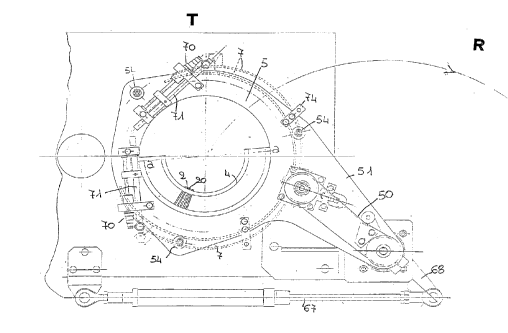
horizontal crown (5) which is in turn solid to a
horizontal arm (51) ~otating about a vertical axis
(b-b) and vertically oscillating between two
positions, a lower one (A) for the engagement of
the crown (5) on the knitting head of the machine
and on the linking station (R) means, and an upper
one (B) for the disengagement of the crown (5) in
order to allow the transfer thereof from one
operative station to the other. Said crown (5) is
also able to rotate in a plane orthogonal to the
axis of the cylinder (1), during the linking of the
article toe, by means of a transmission made up of
a toothed belt (50) and gears (65,66) or similar
device connectable to a corresponding driving
member (56). The crown (5) is also provided with a
member engageable to and disengageable from the
transmission so as to allow for a suitable movement
of the stitches (8,80) to be united, during the
linking operation, with respect to corresponding
linking means;
- cam means (7) for operating the bidirectional
180-overturning of the semicircular sector (4)
about a diametral axis (a-a) of the cylinder (1);
38
2~2773~
- cam means ~201) for moving said spikes (2) and
respective pegs (20) in the article-knitting
station (T);
- mean~ for operating the horizontal rotation of
said arm (51) through a pneumatic cylinder (67)
whose stem has its free end connected to a lever
(68) solid to the lower base of the column (52) for
supporting the arm (51), which column (52) consists
of the stem of a cylinder having axis (b-b) and
a].lowing both the rotation of the arm (51) about
said axis (b-b) of column (52) during the transfer
of the article from the knitting station (T) to the
linking station (R), as well as the vertical
translation thereof along the same axis (b-b)
during the engagement/disengagement of the crown
(5) on the knitting head of the machine or on the
operative means of the linking station (R);
- means for causing said crown (5) to rotate solid
to the cylinder (1) of the needles (3,30) upon the
initial stage of the article linking, with a
vertical pivot (53) solid to the crown (5) and
angularly oscillating between two positions, one
for engaging the crown (5) to an element (73) solid
to the cylinder (1), and the other for engaging the
crown (5) to a stationary plate (200) of the
39
~ ~12773'~ ~
machine to cause it to stop at a predetermined
angular position;
- means for holding the sinkers housing (11) of the
machine in a fixed and predetermined angular
position, with a cam (110) able to freely
oscillating about a pivot (11) solid to a support
(109) whose angular position with respect to the
needles cylinder (1) can be varied and which is
mounted on the fixed part (200) of the machine:
said cam (110) being provided with two curvilinear
grooves (112) developing according to two
corresponding arcs of circumference, each of which
grooves (112) able to make up a guiding element for
a corresponding pin (113) solid to the sinkers
housing (11). In its initial stage of intervention,
the pin (113) closer to the pivot (53) is inside
the corresponding groove (112), that is, engaged
with the cam (110). With the rotation of the crown
(5) solid to the cylinder (1), the pivot (53) runs
onto a side of cam (110) and causes the latter to
rotate. This is cause for the disengagement of the
pin (113) already engaged with the cam (110) and
the insertion of the other pin (113) into the other
groove (112). Further rotating the crown (5) is
cause for the pivot (53) to reverse the rotation of
2~L277~
cam (10) thus allowing the insertion of the first
pin (113) into the relevant groove (112) and
thereby restoring the condition existing before the
cam (110) was set in motion. In this way, during
the rotation of the crown ~5), at least one of the
pins (113) results engaged with the cam (110), and
the sinkers housing (11) results solid all the time
with the support (109), that is, to the fixed part
of the machine;
- cam means (59) for driving said spikes (2) and
relevant pegs (20) before carrying out the linking
of the article toe;
- cam means (58) for operating the opening of the
pegs (20) upon the ~tep of releasing the finished
article;
- a seamer-linker ~130) for the formation of the
hook-up which link the pairs of corresponding
stitches (8,80), said seamer-linker being di6posed
at a preset distance from the article-knitting
cylinder (1), that is, in a predetermined position
of the linking station (R);
- means (95, 96, 97) for ultimately cutting the
linking thread (F) and holding the end of the
thread (Fl) fed by the supply reel.
According to the invention and with reference to
;. . ~ : , , . . . -
2127~3~
Figs. lA-lD of the attached drawings, the cams (7)
for overturning said sector (4) are activated by
corresponding pneumatic cylinders (70) supported by
the arm (51~ bearing the crown (5). Connected to
the stem of each cylinder (70) is a corresponding
rod (71) with a counteracting spring (72) to the
free end of which a cam (7) is fixed. A block (73)
is provided for guiding the excursion of a second
rod (74) which is connected to said cam (7) and
allows the guided support thereof in cooperation
with said rod (71).
Alternatively, with reference to Fig. 3B of the
attached drawings, the said cams (7) are activated
by corresponding pneumatic cylinders (40) solid to
a fixed part (200) of the machine.
Advantageously, according to the invention, the
said cams (7) exhibit a substantially helicoid
profile.
Moreover, said sector (4) is provided with two
rollers (41) which are idly mounted on
corresponding horizontal shafts (42), on either
side of the axis of symmetry (d-d) of sector (4),
and are intended to feel the active profile of said
cams (7) to cause the overturning of sector (4).
According to an alternative embodiment, to allow
42
` ---" 212773~
for the rotation of the crown (5) during the
closing of the article toe, a driving shaft with
vertical axi~ is provided, not shown for clarity in
the attached drawings, said shaft drawing its
motion from the main drive of the knitting machine,
the upper end of which drive is provided with a
sprocket intended to be engaged with a ring gear
(66) connected solid to the crown (5). This allows
the crown (5) to be rotated in the knitting station
(~) in phase with the cylinder (1).
Advantageously, said crown (5) is supported by
the arm (51) by means of three bearings or shaped
rollers (54) which bear a circular "V" guide (57),
parallel and coaxial to the crown ~5)/ disposed at
a position overhanging the latter and suitbaly
spaced apart by a plurality of columns (55).
Advantageously, each of said spikes (2) i8
provided with two heels (21) which project from
either side and are vertically offset to allow for
the reciprocating displacement thereof within the
relevant slots of the sector (4) by means of a
corresponding driving cam (201) provided in the
knitting station (T), and of cams (58) and (59)
provided in the linking station (R).
In addition, each of said pegs (20) is
43
2~2773~
advantageously provided with two heels (22)
projecting from either side and vertically offset
to allow the corresponding spikes (2) to be moved
in the closing, respectively, opening direction,
~pon the hold, respectively, release of the
stitches (8,80) to be united.
Moreover, the height and width of said heels
(21,22) are advantageously chosen according to the
active profile of ~he corresponding driving cam.
The presence of said heels (21,22) allows the
controlled longitudinal translation in both
directions of the spikes (2) and relevant pegs (20)
during the steps of removing the stitches (8) of
the first semirank (x), transferring the latter
onto the needles (30j of the second semirank ~y),
transferring the article from the knitti~g station
(T) to the linking station (R~, predisposing the
stitches (8,80) to the linked and releasing the
finished articl~e.
According to the invention, said spikes ~2) have
their head of wedge-like profile to ease the
capture, respectively, the release of the stitches
(8,80).
Moreover, said spikes (2) have the tip of their
head advantageously bent sideways and internally
44
- `` 212773ll
with respect to the sliding direction thereof, to
allow them to be inserted into corresponding
longitudinal cavities of the needles (3l30) and
thus allowing the stitches (8,80) of the first and
secon~ semiranks (x,y) to be captured.
Moreover, the outer face of the tip of each peg
(20) is advantageously adjacent, that is,
juxtaposed to the inner face of the respective
spike (2).
Similarly, each peg (20) is provided with a
trasverse appendix (27) apt to form a guiding
element for the tip of the corresponding spike (2)
and delimit, in cooperation with a corresponding
recess (28) of the relevant spike (2), a seat (29) :~
for the corresponding stitches (8,80) in closing
condition. :
In this way it is assured that each set of
spikes t2) and respective pegs (20) is provided
with the required rigidity.
According to the invention, the said linker
(130) comprises a framework intended to support:
- a needle bar (90) to support the linking needle
(9), which bar (90) is provided with a seat for a
needle (9)-covering skid which is kept in normally
open position by a spring (19) received in a slot
21~773~
of the same bar (9o) and whose travel is adjustable
by a screw (18): said skid (24) being provided with
a heel (34) engaged to a corresponding cam (25)
which operates the closing thereof upon the
formation of a hook-up chain stitch;
- a bar ~26) at the free end of which a crochet
(14) is fixed cooperating with the needle (9)
during the formation of the hook-up stitches;
- a feeler arm (15) for moving the crochet bar (26)
and which is operated by a cam (16) solid to a
crankshaft (17): said shaft (17) being orthogonal
to the needle bar (90) and connected ther~to by a
connecting rod (23) BO as to make up a crank drive,
that iB, a crank-rod type mechanism for moving the
bar (9o) during the hook-up. This disposition iB
particularly suitable to give the part of the
apparatus provided for the linking of the article,
compactness, constructional simplicity and
reliability.
According to a first embodiment of the
invention, reference being made to Fig. 39A of the
attached drawings, the means (95) for cutting the
linking thread (F) are disposed in proximity of the
operative region of the linking needle (9) on the
same side of the linker (130) with respect to the
46
- 2~2773~
hook-up line.
Alternatively, and with reference to Fîg. 34C of
the attached drawings, said cutting means (95) are
disposed on the opposite side of the linker (130)
with respect to the hook-up line.
Advantageously, and with reference to Fig. 34B
of the drawings, means are provided for inserting
the tail of the linking thread (F) inside the
article, after the formation of the closing knots
for said hook-up, by means of a needle (93) with
skid (94), disposed in front of the closing knots
and able to pick up said thread (F), isert it
deeply inside the article by a translation movement
and leave it therein. At the end of such insertion,
the thread (F) unthreads spontaneously out of the
needle (93) because of the withdrawal thereof upon
the opening of the skid (94).
Alternatively, and with reference to Fig. 38A of
the drawings, a needle (98) with skid (99) is
located on the opposite side of the linking needle
(9) with respect to said closing knots. The thread
(F) clears itself spontaneously out of the needle
(98) owing to the withdrawal of the latter upon the
closing of the respective skid (99).
Advantageously, means are provided ~or
47
.
~ 2127734
elastically tensioning the stitches of the article
during the linking step by using a suction hose
(92) located below the linking means and connected
to the aspirator of the article-manufacturing
machine. The same hose (92) may be used to convey
the finished articles to the respective stocking
stores.
According to the invention, it is possible to
implement said method by using a cylinder (1) for
needles (2,30) having either an even or odd number
of needles.
In particular, with reference to Fig. 43 of the
drawings, the axis (a-a) of rotation of sector (4)
i8 made to pass through two diametrally opposite
needles of cylinder (1), so that the removed
stitches of the first semirank will be in a number
equal to that of the needles (3,30) of cylinder (1)
minus two, divided by two, and result transferred
onto as many needles (30) of the second semirank.
However, upon completion of the hook-up, also the
two stitches (80) of the two needles (30) which
result at the ends of the second semirank and have
been excluded from the procedure for the trasnfer
of the stitches (8) of the first semirank, are
likewise linked.
48
212773'~
With reference to Fig. 44 of the drawings,
provision is made for the axis (a-a) of rotation of
sector (4) to pass between two diametrally opposite
pairs of needles (3,30) of cylinder (1). In this
way, the number of transferred stitches will result
equal to half the total number of needles (3,30).
With reference to Fig. 45 of the attached
drawings, in case of an odd number of needles
(3,30), the axis (a-a) of rotation of the sector
(4) is made to pass in correspondence of a needle
(30) of the second semirank and in correspondence
of the center line of the needles (3,30) located at
the end of the respective semiranks. In this case,
the stitches to be transferred amount to the total
number of needles minus one and divided by two, and
the number of needles (30) of the second semirank
is equal to the number of needles (3) of the first
semirank plus one.
To move the plate (37) away from the knitting
head of the machine, without altering the operating
capability of the means intended for holding the
knitti.ng thread, provision is made for mounting the
machine thread-guide unit (47,48) on a bracket (43)
connected to the column (45) of the plate (41),
with a pawl (46) for activating/deactivating the
49
- 212773~
connection. In this way, the lifting of the column
(45) is cause also for the lifting of the thread-
guide unit (47,48) thereby allowing the actuation
of the means for the removal and transfer of the
stitches (8,80).
The operation of the described apparatus,
reference being made to a preferred embodiment
thereof and assuming the disposition of the needles
(3,30) to be like the one of Fig. 44 of the
drawins, is as follows.
Upon completion of the knitting of the article
and of the transfer of the stitches (8) of needles
(3) of the first semirank (x) onto the needles (30)
of the second semirank (y), the cams (32) for
driving the needles (30) operate the lowering of
the latter down to a level below that of the nib
(60) of sinkers (6), with the corresponding pairs
of stitches (8,80) being disposed in retained
position. Afterwards, the sector (4) is brought to
its initial position through an overturning thereof
opposite to the one having determined the transfer
of stitches (8) of the first semirank. Thereafter,
the cylinder (1) is rotated through 180 with
respect to the sector (4) to bring the latter
exactly in correspondence to the needles (30) of
r ~ G ~
-- ~2773~ ~
the second semirank. At this point, the cams (31~
oper-ate the lifting of the needles ~30), with the
sinkers (6) being closed, until the corresponding
stitches (8,80) being retained by the sinkers (6)
result in a predetermined position with respect to
the stem of the respective needles (30)l that is,
in a position to allow for the subsequent removal
thereof by the same spikes (2) which have
transferred them. Afterwards, the needles (30) are
lifted, with the sinkers (6) being open, up to move
the pairs of stitches (8l80) to the level of said
spikes (2) which, at this point, are made to
advance to be closed by the relevant pegs (20), so
as to capture the stitches (8,80). Then, the
needles (30) are moved down ~o as to have the pairs
of stitches (8,80) retained by the spikes (2) and
the article released from the needles (3,30).
Thereafter, the crown (5) is lifted together with
the sector (4), with the article being retained by
the spikes (2), by means of the cylinder (52). At
this point, the suction hose (100) is lifted. Then,
the actuation of cylinder (67) causes the rotation
of the column (52) about the axis (b-b) and of :~:~
crown (5) solid thereto, the latter being supported
by the arm (51) which is rigidly connected to the
:
51
- ~` 212773~
. .
same column (52~. At the end of this rotation, the
crown (5) is made to move in correspondence of the
linking station (R) down to a level suitable for
allowing the intervention of cams (59) to move the
spikes (2) with relevant pegs (20) in closed
condition. Afterwards, the spikes (2) are thus made
to advance centripetally until the respective
stitches (8,80) to be joined result angularly
disposed equidistantly, and the distance between
any two adjacent pairs of stitches (8,80) i6 equal
to the linking shed, the latter being chosen
according to the desired hook-up fineness. The thus
disposed stitches to be joined (8,80) result ready
for the linking operation which is carried out by
the needle (9) supplied with the thread (F), in
association with the chain-guide (10) and crochet
(14). During the linking, the crown (5) is driven
into rotation by the transmission engaged to the
toothed crown (66). Shed by shed, the needle (9) is
inserted into a pair of corresponding stitches
(8,80) thereby forming a plain chain hook-up
stitch. After the execution of the last linking
stitch, the needle (9), with the cooperation of the
crochet (14) and chain-guide (10), makes two or
more closing knots. Then, the thread (F) is
52
` 21~7734
captured by the needle (93), which has its skid
open, and after the closing of the skid, the sa~e
nePdle (93) is made to advance inwardly of the
article and the ~hread (F) finally cut. In this
way, the tail of the hock-up thread (F) is inserted
within the article by the further advancement of
the needle (93). The withdrawal of the needle (93),
with the skid (94) being open, allows it to
spontaneously leave the said tail of thread (F).
And this thread, once withdrawn out of the needle
(93), results grasped by the article stitches and
unable to come out thereof. Upon completion of thi~
stage, the cam (58) is made to act upon the spikes
(2) of sector (4) which leave the relevant stitches
(8,80) already united, thereby allowing the
finished article to be unloaded in its right-side
out, that is, ready-to-use condition, through the
hose (92).
Practically, all the construction details may
vary in any equivalent way as far as the shape,
dimensions, elements disposition, nature of the
used materials are concerned, without nevertheless
departing from the scope of the adopted solution
idea and, thereby, remaining within the limits of
the protection granted to the present patent for
~12773~
industrial invention.
54