Note: Descriptions are shown in the official language in which they were submitted.
~_ FIELD OF THE lNv~ lON 212~7 ~ 3
This invention relates to multiple-purpose cooking
assemblies, which can be easily transformed into a variety of heat-
generating units such as barbecue units, space heaters, ovens, and
5the like.
BACKGROUND OF THE INVENTION
The great appeal of outdoor activities during warm summer
months means that there is a demand for related commodities. A
preferred such activity is cooking foodstuff outside of the house,
10in the garden for example, over a barbecue grill. Typically, the
heating fuel for these barbecue grills is charcoal; or, if trekking
in isolated areas, locally available wood chips, or propane fuel
(carried by the trekker) may be used.
Those seeking better value for their investment have
15developed the concept of transformer heating units, i.e. a single
integral unit that can be easily transformed into various alternate
modes. Typical of these modes are: foodstuff cooking units;
radiating space heaters; frying, baking, steaming, roasting, and
smoking units; for charcoal broiling; and including complementary
20means to serve with the cooking mode as a windbreak, as a dishpan
or as a washpan.
Transformer heat-generating portable units have been
known for a number of years. Such transformer units date back at
least as early as the heating unit disclosed in United States
25patent No 2,237,081 issued April 1, 1941 to the Owens Smokeless
Orchard Heater inc. corporation.
~- United States patent No 2,907,316 issued in 1959 to F~a~ 3
Windust further discloses a camp stove which can be transformed
into a cooking unit or as a stove for use inside a tent.
United States patent No 3,791,368 issued in February 1974
to William HUNT discloses a multi-purpose cooking assembly, which
can be alternately used as a stove, as a griddle, as a toaster, as
a pressure cooker, as a charcoal broiler, and for baking, steaming,
roasting, or smoking foodstuff. This cooking assembly can be
easily transported like a suitcase. It boasts a propane burner
assembly for connection to a propane fuel reservoir, and\or
alternate fuel source such as charcoal briquet in a suitable
carrier, and\or prepackaged wood chips used when smoking the food.
As suggested in figure 3 of the drawings in this latter patent, a
variety of griddle, grill, carriers, pans, and other paraphernaliae
are included as prepackaged detachable elements inside this cooking
assembly, for use when necessary. For transport, these elements
are generally nested into one another, as illustrated in fig 2,
whereby support means 34, 38, 60 releasably interconnect these
elements.
In United States patent No 3,783,855 issued in January
1974 to Vann NEWINGER, there is disclosed a heat-radiating unit 12
pivotally mounted into a drawer-like casing. One face 62 of the
unit 12 forms a grate made of heavy wire mesh, while the opposite
face 58 of unit 12 forms a flat panel. When radiator 12 is pivoted
to a first position where face 58 becomes horizontal and faces
upwardly, foodstuff can be heated or fryed thereon; when radiator
212~ 783
~a is pivoted half a turn to a second position whereby face 62
becomes horizontal and faces upwardly, a barbecue surface is
formed; and when radiator 12 is oriented vertically, as illustrated
in figure 1, it becomes a space heater.
As we have seen, these transformer heating\cooking units
are usually destined for outdoor use. Indeed, the combustion gases
generated by the combustion of the fuel (charcoal or propane) are
simply released to the air, without being channeled out through
specific flue means. In the garden or in the woods, this has no
drawback; but if one would like to use such a cooking\heating
transformer unit inside a house or inside a flexible sheet tent,
very real safety hazards would result, namely, severe intoxication
(and possibly even death) from combustion gases (e.g. carbon
monoxyde) smoke inhalation.
OBJECT~ OF THE INVENTION
An object of the invention is to extend the applications
of existing transformer cooking\heating units, to indoor use.
A more specific object of the invention is to provide a
transformer heating unit, having six different modes, namely: as a
stove, a cooking oven, a roaster, a barbecue grill unit, a
foodstuff smoking unit, and as an indoor gas-burning space heater.
SUNMARY OF THE lNVL.. ION
Accordingly with the objects of the invention, there is
disclosed a transformer heating unit defining: (a) a main self-
standing Iframe, defining a generally box-like enclosure having a
bottom tray and a top mouth and air feed means for enabling outside
air flow over said tray within said enclosure; (b) independant,
adjustable, heat-generating means, mounted spacedly over said tray,
for self-generating heat within said enclosure; (c) first means,
to be combined with said main frame for transforming said heating
unit into a an indoor space-heating furnace unit, said first means
including flue means for discharge of combustion gases generated by
said heat generating means at a distance from said heating unit;
(d) second means, to be combined with said main frame for
transforming said heating unit into a cooking oven; (e) third
means, to be combined with said main frame for transforming said
heating unit into a roaster; (f) fourth means, to be combined with
said main frame for transforming said heating unit into a barbecue
grill unit; and (g) fifth means, to be combined with said main
frame for transforming said heating unit into a foodstuff smoking
unit; wherein said first to fifth means are all detachably mounted
together into said main frame for transportation or storage.
BRIEF DESCRIPTION OF THE DRAWINGS
Figures 1 and 2 are front and rear perspective views, respectively,
of the indoor space heating furnace mode of the present transformer
unit;
Figures 3 and 4 are front elevational and top plan views,
respectively, of the barbecue grill mode of the transformer unit
according to the invention;
Figure 5 is a perspective view of the dismantleable cover portion
used in the barbecue grill mode of figures 3-4, shown in extended
condition;
21 2? 783
~igure 6 is a perspective view of the fire box forming part of the
stove mode of the present transformer unit;
Figure 7 is a perspective view of the self-standing main frame
forming part of all the six heating unit modes of the present
invention, and showing a propane gas burner being supported
spacedly over the bottom debris-collecting, removable tray;
figures 8 is an isometric view of the combined oven, barbecue grill
and smoking unit modes of the invention;
figure 8a is an isometric view of the stove mode of the invention,
with one flap of the cover portion being opened so as to be used,
when the firebox has been removed, as a foodstuff-supporting
tablet;
figure 9 is a front elevation of the roaster mode of the present
transformer unit;
figures 10 and 11 are enlarged sectional views taken along lines
10-10 of figure 2 and ll-11 of figure 6, respectively;
figure 12 is a view at an enlarged scale of the pilot unit
appearing in the area circumscribed by arrow 12 in figure lo;
figure 13 is a cross-section at an enlarged scale of the smoking
element of the present transformer unit, being fitted to the pilot
unit shown in figure 12, and illustrating the wooden chips to be
smoked and the pilot flame; and
figure 14 is a cut away elevation of the lower portion of the
collar member surrounding the pilot unit in the smoking element of
figure 13, particularly showing the air intake ports.
212~7~3
~- DETAILED DESCRIPTION OF THE l_.V~. lON
Figures 5 to 7 illustrate the three main elements of the
present transformer unit 20. Indeed, the combination of elements
illustrated in figures 5, 6 and 7 contain the three main detachable
elements of the present invention. More particularly, figure 7
illustrates the main, self-standing box-like frame 22 of the
transformer unit 20, defining four cross-sectionally L-shape,
upright corner legs 24, a removable tray 26 supported over ground
by tracks 26a being anchored to the legs 24, two lateral fixed side
walls 28 and 30 and a rear side wall 32 being edgewisely anchored
to corresponding pairs of successive legs 24, and a front door
panel 34 being hingedly mounted by pivot means 36 (fig 8) at its
bottom edge to the mid portion of the two front legs 24.
Panel 34 is pivotable manually by grasping a front handle
35. Pivot means 36 are upwardly offset from the tray 26. A
flooring panel 27 is adapted to support a propane burning unit 38;
panel 27 extending spacedly over tray 26 and being edgewisely
anchored to wall 32 and 26a and being preferably pierced by a
number of air circulation bores (not illustrated).
Fixed side walls 28-32 are adapted to enclose and are
correspondingly dimensioned to receive a firebox 40 (illustrated in
fig 6), the firebox being supported by the permanent flooring 27.
Firebox 40 has a lower glazed window 59 and is bottomless
(see fig. 11).
The extensible cover part 42 illustrated in figure 5 is
adapted to fit against the external face of the side walls 28-32
212~7~3
~ee figure 8), but inwardly of the door 34.
Pivotally mounted door 34 can be used in opened position
(fig 8a) to look at the flame of burner unit 38 through window 59,
or as a shelf to hold foodstuff, to be cooked (the firebox 40 must
be removed in this case, when the oven mode is selected). However,
for large foodstuff portions such as poultry, the cover part 42 is
removed for roasting, as suggested in fig 9.
Tray 26 is edgewisely freely supported by cross-sectionally L-
shape tracks 26a, these tracks 26a being anchored at their end
lo portions to legs 24. As illustrated, the tracks 26a extend for
example short of the respective side walls 28-32, whereby a gap is
defined therebetween, these gaps forming air intake ports for
feeding the combustion of propane. However, it is understood that,
in another model within the scope of the invention, tracks 26a
could very well merge with corresponding walls 28-32, provided a
number of small through-bores (not illustrated) are made into the
lower portions of walls 28-32 and\or into the flooring 27 above the
tray 26, so as to enable ambient air to feed the propane gas
combustion generated by the propane burner 38 resting over the tray
26. Also, the front track, 26a', may e.g. extend further upwardly
than the remaining tracks 26a, to edgewisely freely abut with the
bottom edge of the hinged door 34, and also downwardly, to the
ground G.
To facilitate handling of the main frame 22 of the
transformer unit, handles 44 are provided, projecting outwardly
from side walls 28 and 30. The inner faces of side panels 28-32
21277~3
further carry horizontally extending and registering rails 46, (see
figs 7 and 10) e.g. two vertically spaced rails each, for slidingly
receiving grills 48, such as barbecue grills (see also figs 3 and
4), or roasting trays 110 (see fig 9).
The bottom tray 26 is releasably mounted by tracks 26a in
between the supporting legs 24, particularly in view of periodic
cleaning purposes (i.e. removing ash, cinders, or other debris
having accumulated therein). Cross-sectionally L-shape tracks 26a
are anchored to the inside V-shape face of the four supporting legs
24, and the tray 26 made to freely abut thereon at its four corner
portions, whereby the tray be freely upwardly removable therefrom.
Tray removal could be done by upwardly tilting one end thereof,
thus enabling release of the tray from the opposite side supporting
tabs; or these support means could also be for example small
notches (not illustrated) about two consecutive side legs 24, 24,
for example the two ''rear'' legs 24, 24, of the heating unit 20,
to enable horizontal sliding motion of the tray 26 through these
notches.
Propane burner unit 38 is operatively controlled through
a control knob assembly 50 (see figs 9 and 10) projecting outwardly
from the front flange 26a', beneath door 34.
Fire box 40 is shown in perspective view in fig 6 and in
cross-section in fig 11. Fire box 40 is box-shaped, including two
opposite side walls 52 and 54, and front and rear walls 58 and 56.
Front wall 58 includes a lower window 59 within which is fitted a
glass window pane. Side walls 52 and 54 carry each a number of
212~7~3
~aced, parallel, horizontally-extending plates 60, 62,
respectively, e.g. two for each side wall 52 and 54 as illustrated
in figure 11. Each plate 60 and 62 straddles the front and rear
walls 58 and 56, and defines a right-angle inner flange 60a, 62a,
anchored to walls 52 and 54 respectively, and a free end edge 60b,
62b, extending short of walls 54 and 52, respectively, whereby a
circonvoluted smoke passageway ~arrows 64) is formed therebetween.
Sinusoidal passageway 64 works as a heat exchanger, dissipating
heat laterally through walls 52-58, as the warm combustion gases
move naturally upwardly through the firebox.
In operation, the combustion gases from the propane gas
burner 38 first engage through the large bottom open mouth 66 of
the firebox 40, then along the sinusoidal pathway 64, to exit
through a small outlet 68a made through the top wall 68 of firebox
40. (Top wall 68a edgewisely merges with the four side walls 52-
58) Preferably, a plurality of thermally radiating fins 70 are
edgewisely anchored to the exterior face of walls 56 and 58, along
a vertical axis and spaced from one another. Fins 70 promote heat
dissipation, outwardly from the firebox 40.
A flue pipe 72 is fitted at its bottom end into smoke
outlet 68a, for conveying combustion gases away from the immediate
surroundings of the heating device 20, e.g. through and beyond the
roof of a building into which the heating unit 20 is located, so as
to prevent smoke intoxication by the occupants.
In figure 6, the firebox 40 preferably includes two
horizontally spaced apart top ears, 74, being edgewisely anchored
- 2I277~3
t~ the top edges of fin walls 56 and 58. Ears 74 are provided to
receive a thermally insulated handle, not shown, to be able to
safely hand-grasp the firebox 40 for displacement thereof,
particularly when the firebox is very hot. Also, the top wall 76
(fig 8a) thereof should be flat and horizontal in operative
position, to be able to directly support cans and the like for
heating foodstuff inside the can, once a flap 84 or 86 of the cover
part 42 has been opened to clear the way for the can.
Firebox 40 is accordingly used only when the transformer
unit 20 is in its space heating (furnace) mode, or in the stove
mode. The firebox 40 becomes operative upon being releasably
mounted inside the main self-standing frame 22 illustrated in fig
7 (the grills 48 supported by tracks 46 must have been previously
removed therefrom). The flue pipe 72 is fitted to the gas outlet
68a of the firebox only after the firebox has been inserted inside
the enclosure of the box-like frame 22, through a corresponding
aperture 78 made in wall 92 of hinged flap 86 of the cover part 42
(said aperture 78 being normally releasably closed by a slitted
plug member, 80, see fig 8a).
Preferably, and as suggested in fig 10, a thermocouple
is provided as a safety measure in preventing accidental unignited
combustion gas outflow of the pilot unit (figs 12-14) or the
propane gas burner 38; i.e., as soon as the fire stops, the propane
gas feeding line is automatically closed.
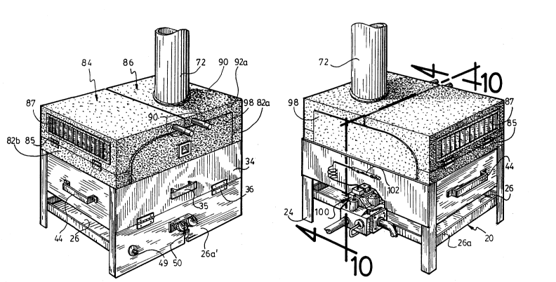
The cover unit 42 illustrated in fig 5 is used as a cover
when the present heating unit 20 is in the following modes: oven,
21~77~3
~oking unit or barbecue unit; or used as a double-walled thermally
insulating member, when associated with the firebox 40 in the space
heating furnace mode. Cover unit 42 includes a central open frame,
82, of U-shape, and two pivotable flaps, 84 and 86, hingedly
mounted at 85 to the two opposite legs 82a and 82b of the frame 82.
Cover portions 84 and 86 are pivotable from an opened condition,
illustrated in figs 3-5 where these two cover portions 84 and 86
extend in opposite directions; through a partially closed
condition, illustrated in figs 8-8a, in which cover portion 86 is
turned half a turn to come within open frame 82 while cover part 84
remains in its said open condition; to a fully closed condition,
illustrated in figs 1-2, where both cover flaps 84 and 86 are
pivoted inwardly to fit within the open central frame 82. Frame 82
further includes a U-shape extension 88, projecting transversely
from the outer ends of the legs 82a and 82b. U-extension 88 forms
along its two side legs 82a, 82b, an abutment member for edgewise
abutment by and for defining the limit condition of the cover flaps
84 and 86 in their fully opened (extended) positions.
Preferably, the lateral cover flaps 84 and 86 each
includes a vertical, end grilled outlet, 87, operative in the
space-heating furnace mode (figs 1-2); and a front handle, 90, for
grasping the front cover flap in view of pivoting same. This is
desirable in that the cover portion 84 and 86 is envisioned to be
made from a metallic compound, which is thus thermally conductive
and thus direct physical contact therewith would otherwise mean
severe skinburns during operation of the heating unit 20.
11
21277~3
_ Each cover flap 84 and 86 defines a generally L-shape in
cross-section, with the lower leg forming a horizontal foodstuff-
receiving tablet, 92, in the opened condition of these cover flaps.
Preferably, this tablet 92 defines upturned front and rear flanges,
92a, 92a.
As illustrated in figures 5, 7 and 8, the base leg 82c of
the main U-shape frame part 82 of the cover 42 carries a pair of
male latch members 94, and the upper edge of the inner face of the
rear wall 32 of the self-standing casing 22 carries a pair of
complementary female latch members 96, whereby members 94 and 96
constitute an interlocking latch means for releasably
interconnecting the cover member 42 into the enclosure of the self-
standing casing 22.
As illustrated in figs 1 and 5, cover flap 86 further
includes a pair of approximately semi-circular extension panels,
98, (the inner edge thereof being however straight, as illustrated)
being fixedly carried on the exterior side of and laterally
projecting from the front and rear flanges 92a, 92a. These panels
98 are larger than the flanges 92a, and each of these panels 98 is
specifically shaped to conformingly match the edgewise contour of
the corresponding pair of front or rear flanges 92a from the cover
flaps 84 and 86, when the cover flaps 84 and 86 are in their fully
closed condition illustrated in figs 1 and 2 of the drawings.
Therefore, it is understood, as clearly shown in fig 1, that, in
the space heating furnace mode of the invention, the front wall of
the furnace is formed of the combination of panels 92a, 98, 34,
12
212~ 7~3
q~a', and of the front ends of legs 82a and 82b, which, taken
together, form a coextensive full panel member completely
concealing the enclosure of the furnace assembly 20. A thermometer
99 is mounted in panel 98.
The oven thus comprises a propane gas burner, to which is
preferably coupled a thermostatic control box 100 (fig 2) with a
heat probe 102 for selection of the desired temperature. A
thermocouple, and an electronic starter 49 are also further
provided.
The thermostatic control box will start the fire and stop it in an
automatic fashion, thereby enabling use of the transformer heating
unit 20 into the space-heating furnace mode thereof (when frame 22
is combined with the fire box 40).
Figure 9 illustrates the roasting mode of the transformer
heating unit 20. The conventional rotatable fork rod 104 is power
rotated by the motor unit 106 at one end and freely journalled at
its opposite end to a yoke member 108. Fork rod 104 may embroach
e.g. a poultry P, spacedly over tray 26. A generally concave
grease-collecting pan 110 is releasably installed beneath the fork
rod 104, above tray 26, and being edgewisely engaged into a pair of
opposite lateral tracks 46'. Motor casing 106 and yoke member 108
are both anchored by anchoring members 112, 112, to the top edge of
side walls 28 and 30, respectively.
Figures 10 and 12-14 illustrate the smoking mode of the
present transformer unit according to the invention. A pilot unit
114 is installed at a position proximate the propane gas burner,
-
2l2~7a3
, at the outlet end of a propane gas delivery line, 116. A
cylindrical coupling member 118, diametrally larger than pilot 114,
is fitted to the downstream (outlet) end of the line 116, coaxially
around the pilot unit 114. A large cup member lZo is further
provided, defining a bottom wall 120a and a cylindrical wall 120b,
the cylindrical wall being edgewisely integral to the bottom wall
120a. A boring 120c is made centrally of bottom wall 120a,
coaxially with cylinder 120b, and defining a radially inner
diameter matching the external diameter of the cylindrical coupling
member 118 for friction-fit interlocking engagement therebetween.
Cup member 120 encloses wood chip particles, C, in such
a quantity that the height achieved by these wood chips does not
extend beyond the top mouth of coupling member 118, to prevent
undesirable wood chip overflow inside the coupling member 118 and
into pilot unit 114 (the wood chip would ignite and inflame, rather
than simply smoking). The top open mouth of cup cylinder wall 120b
is releasably closed by a cap, 122. Cap 122 includes a plurality of
small through-bores 124, through which smoke generated by unignited
but warmed up wood chips C will escape. Preferably, a handle, not
shown, is mounted to cap 122 to facilitate its handling.
Cylindrical coupling 118 further defines radially
disposed, combustion air intake ports 118a at its lower portion,
below of and clearing the boring 120c, for sustaining the flame of
pilot unit 114.
As illustrated in figures 12-13, pilot unit 114 is
coupled to the propane gas line 116 through a coupling means 126,
14
212~7,~3
~ncluding a discoid plate 126a having a large radius. Discoid
plate 126a supports the bottom edge of the upright cylindrical
coupling 118, via a radially-outwardly diverging annular projection
118b at the bottom edge of cylinder 118, projection 118b forming an
annular seat for the coupling 118.
As illustrated in fig 13, the cylindrical tube 118 around
the pilot unit 114 extends short of the cap 122. However, it
should be understood that, in an alternate mode within the scope of
the invention, this cylinder 118 could extend up to and with its
top mouth 118c abutting against this bored cover of the smoking
unit (not illustrated). This embodiment would be advantageous, in
that it would positively prevent the pilot flame from generating
full ignition of the wood chips C, whereas one needs only to smoke
them.
Preferably, cap 122 includes a central inturned convex
projection, 122a, in axial register with cylinder tube 118 and of
an external diameter matching that of the internal diameter of tube
118 so that, in a topmost condition of tube 118 abutting against
cap 122, cap projection 122a will engage through the top mouth 118c
of tube 118, in view of substantially preventing the flame of pilot
unit 114 from igniting the wooden chips C.
It will be readily understood by those skilled in the art
that the propane gas delivery line 116 is to be operatively
connected to the electrostatic control box, loo (figs 2, 4 and 10).
Front control knob 50 is connected to propane burner 38 by line
128, and to the control box 100 by line 130. Control box 100 is
21277~3
i~self connected to a propane gas reservoir, not illustrated.
16