Note: Descriptions are shown in the official language in which they were submitted.
2 1 2 7 ~ ~ ~
~1- :, .
FIELD OF THE IN~ENTLON ;~ :
The pr~sen-t invention relates to a module Eor rapid .
interconnection, typically between the telephone network :
and a su~scriber, oE two monopair telephone lines, this
5 module presentin~3 characteristics of tightness which . .
enable it to be installed out of doors, for example in
an aerial circuit.
BACKGROUN~ OF THE INVENTION
Modules of this type are at present widely marketed ;~
10 by Applicants under reference "MX.... ", and are therefore ~ ....... ;
well known. Fur-thermore, they are largely described in
documents US-A-4 6L4 396 and FR-A-2 661 283. They are
:: :
~: based on the use of self-strippin-3 tubular plugs, conse- :... :.quently split at at least one o~ their two ends. In that :.
15 case it sufEices to possess a screwd:river to make the :: :
connections.
A self-stripping tubular split plug .is an extremely
~ ri~id element. If it is used with a wire whose core is :
-~M: made of steel, this steel core deforms the slot of the
20 plug, enlarging it in order to be able to penetrate .
therein. It is then impossible subsequently to introduce
: : wires whose core is of a smaller diameter, as they would
: float inside the slot. :~
Furthermore, several types of modules are provided
at the present time, depending in particular on whether
or not it is question of a module Eor protection against .~
: overvoltages, which is fairly penalizing as far as the ~.
manufacturing, storage and management costs are concerned.
It is an object of the invention to propose a module
:~ : 30 which is :nore practical, more universal and tighter than .~
the modules mentioned above and presently marketed by . ~.. -
Applicants.
~; SUMM~RY OF THE INVENTION
:
To that end, this invention rela-tes to a module
for the rapid int~rconnection of two monopair telephone
::,:. '~
' . 2 1 2 ~
lines, typically for the interconnection of a monopair
line of the telephone network with a subscriber's mon~pair
line, characterized in that it is constituted by four
elements adapted to be assembled on a metal rail for
support and grounding, namely:
. a first element, or base element for conn~ction
of the incomillg line, which is fixed on this metal rail
for example by clipping, and which at least comprises
two channels for introduction of the two wires of the
incoming line, typically that of the telephone network,
mean, further being provided to connect to the me~al
rail a metal contact for grounding which traverses this
base element;
. a second element, o~ intermediate element, which
covers the first element and which contains the major
part of the connections for linkage between these t~o
telephone lines, these connections being in the form
of rigid or se~ni-rigid metal pieces, such as blades,
tuning-fork contacts and~self-stripping contacts, which
20:~are fitted in this intermediate element, a discontinuity
for electrical linkage being, however, made therein for
;each of the two line llnks,~and these~connections nece~sari~
:ly comprising, on the one hand, two metal contacts each ; :
with at least one self-stripping slot which are prominent
1n the direction of the metal rail .so as l:o receive,
in se:lf-stripping connection action, t~e two said wires
of the incoming line previously introduced in said channels
of said base element, and necessarily comprising, on
the other hand, two other metal contacts each ~ith at
least one self-strippin~ s14t which are, a contrario,
prominent in the direction opposite the metal rail so
as to be able to receive, in self-stripping connection
: action, the two wires of the outgoing line, typically : :
the subscriber's line, which are to be connected to the
two respestive wi'res oE said incoming line;
.. :.
I 2 ~ 2 ~ ~ ~ 9
-3-
. a third element, or upper element for connection
of the outgoing line, which is constituted, in manner
known per se, as an upper half-bush Eor r~pid, self-
st~ipping connec-tion oE a monopair line, and which is
: 5 therefore conven-tionally provided wi-th two parallel chan-
nels for receiving and guiding the two strands of line
to be connected, this third element covering a fir~t
part of the second element by mounting, in cooperation
with self-st~ipping connection action, said other two ~:
self-st~ipping metal contacts, and this third slement
being conventlonally traversed by a screw, median and
perpendicular to the metal rail, which also completely ~ .
traverses the second element as well as at least a part . : :
~:~ of the first element to screw in a nut or tapping, in
15 that case forcing the said three elements:to come together - ;
and consequently ensurlng, in ~nanner~known per se, the -.
~ self-stripping connection of the four~line strands; ~ :
r~ . and a ~ourth element which covers, by fitting, :~
the remaining part of the second element, thus being ::
:20 :positioned:side by side with the third element and substan-
tially:at the same~level:as the latter, this fourth element :~
thus ~fitting by five ~er;~inals for~electrical connection,
: of~which one termin~l for linkage to said metal grounding
;:: contact which itself traverses the first and the second
el:~ment, and of which two other pairs of terminals which
are respectively connect~d, for example by connection
on tuning fork contacts, to each respecLive side of said
two discontinuities for electrical linkage which are
provided in the second element, and this fourth element :
: 30 Eorming receptacle for an electric circuit which is connec~
ted on these five terminals and which at the minimum
ensures the two missing electrical linkages, by reason
: of s~id discontinuities, in the connections contained ~.:.
in the second element.
; .~ ~ .:
2:~7~49
BRIEF DESCRIPTION OF THE DRAWINGS
The invention will be more readily understood and
other characteristics will appear Erom the following
description of a non-limiting embodiment oE this rapid
interconnection module, with reference to the accompanying
'~ schematic drawings, in which:
Figure 1 is an overall view, in perspective, of
the module as delivered to the customer before any connec-
tion.
Fig~re 2 shows this same module after assembly on
its metal receiving rail and connection o~ the two pairs
of wires.
Figure 3 is an exploded side view of the module
of Figure 1~
15~ Figure 4 is a vertical and median longitudinal section
of the module of Figure I, mounted, however, on its recei-
vin~ raiI.
Figure 5 is a partial horizontal section showing
th- detail of th~e ground connection of this module on
20 ~its nletal receiving rail.
Figure 6 is a longitudinal and vertical section
;of~ the~module of Pigure~2, made at the level of two conju-
gate~receiver channels for two strands to be interconnected
to each other.
25~ ~ Figure 7 is a small detailed view in section, made
along~VII-VII of Figure 6.
Flgure~8 is a view from the rear of the intermediate
element, on which only the metal contacts and blades
are visible.
Figure 9A is, on -the contrary, a view from the front
of this sam~ intermediate element.
Figure 9B is a view similar to Figure 9A, but in
a view from the rear of the fourth element of the module.
Figure 10 is an exploded structural perspective
view of the various metal elements forming all the connec~
,;' .
8 ~ 3 ~ ~:
-5- .~ ~
:
tions that this module contains, and in accordance with ..
two embodiments of its fourth element.
Figure 11 is an electrical. diagram of thi.s module .
in the first of these two embodiments of its fourth element.
Figure 12 is an electrical diag~am oE this module
in the second of these two embodiments of its fourth .-
element. .
Figure 13 is an electrical diagram of this module ~.
~ in a third embodiment (not shown structurally here) of
'~: 10 its fourth element.
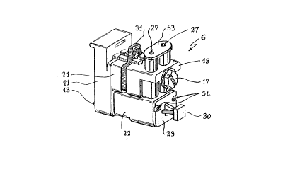
DESCRIPTION OF PREFERRED EMBODtMENTS
Referring now to the drawings, and firstly to Figures ~ ~.
1 to 6, it is question of a module 6 for rapid interconnec- .
tion of telephone lines which is similar to those described
15 in Patent US-A-4 614 396 mentioned above and ~hich are ~.
: now largely marketed under general reference "MX... ".
Nonetheless, this module 6 presents a number of
particular features:
It is composed of four elements 11, 21, 18, 22 which
: 20 are mechanically assembled and cooperate from the stand- :~point oE connections, and it is designed to be mounted -~
on a metal rail lj of the "DIN rail" type, of which one ;~
; of the two longitudinal flanges 7 is pierced with couples
of adjacent slots 8, 9 which define therebetween a narrow
metal band 10, this assembly 8, 9, 10 b.~ing provided
to receive a ~uning fork contact for grounding the module .: :
: 6 which, as will b~ seen in greater detail hereinafter,
: is m~unted on the narrow band 10.
A first element of the module 6 is its base element
30 11 which is provided to be fixed on the metal raid. 1 ::
by clipping, thanks to hooks 12, 13. ~ :
This base element 11, which may also be called lower
ring by analogy with the known devices, is made of moulded
plastics material, a., is the whole body of module 6.
~: 35 Perpendicularly to the longitudinal direction of
, .
~ ~2'~g~
the rail 1 and over virtually the whole of its length,
-there are pierced -two bllnd channels 14 (Figures 3, 5
and 6) which are dimensioned to receive the two wires
or strands 15 of the incoming monopair telephone line,
i.e. in general the telephone network line. These strands
15 are visible in Figures 2 and 6.
Like th~ module., "MX..." presently on the market
and in particular like th~ one descrlbed in document
FR-A-2 661 283 mentioned above, this lower element 11
10 imprisons a nut 16 (.Figure 9) which receives the threaded
end of the median master screw 17, which is now very
.. ..
conventional, which, in accordance with the same process
as for the devices according to the two documents ~S-A-4
614 396 and FR-A-2 661 283, on screwing in this nut 16,
forces at least the lower element 11 and the upper element
18 of the module 6 to move together, which, as will be
~ : explained again for this module hereinafter, conventionally
m~ ensures the self-stripping connection of the:two pairs
of wires to be interconnected, without it being necessary
20~to use something other than a simple screwdriver.
Element 11 is traversed by a f:irst half of a double ::
, :
tuning-fork contact 19 (cf. also Figure 10) which is .:~
pro~ided to mount the corresponding band or strip 10 . .::::
of the rail 1 and thus ensure a ground connection. .: :
Finally, a double hook 20 made of plastics ~aterial, .~
: moulded with the body of element 11, is fixed by clipping ~:~
in the body, provided to that end, of the second element
;:;; 21 of the module 6, thus solidly connecting these two
elements 11 and 21.
Th~ purpose of this latter element 2L, or interlnediate
ring, is to ensure linkage connections between the base
element 11, on the one hand, and the last two elements
18 and 22 of the module 6, on the other hand. It is in .
~:the form of a body oE moulded plas-tics material in which ...
:35 are formed housings for metal connections which, as will
. ' ' .
: .
2 ~
-7
be explained hereinaEter with reEerence likewise to Figures
8 and 9A, and especially lO, is in the form of an assembly
of rigid or semi-rigid m~tal strlps and tuning-fork con-
tacts, or, in other words, in the form of cut-out metallic
circuits.
It should be indi~ated at this stage that the purpose
of these cut-out circuit connections is at ledst electrical-
ly to connect, within the module 6, the two couples 15 ~ -
and 23 of strands of line to be interconnected. A particu-
~'~lO lar feature of these connections is that they present,
'' for each strand, a point 24, 25 (Figure 8) of interruption,
in this intermediate element 21, of the electrical circui~ ,
for interconnection between an incoming strand 15 and
the corresponding outgoing strand 23. It is in this ~ourth
~element 22 that the two staples are located which, when
this element 22 is fitted on element 21, then ensure
electrical contlnuity by~short-circuiting the free spaces
24 ~nd 25 re,pectively.
The third element 18, or upper ring, calls for fewer ~-
20~commentS~since, as a whole, it is~question of~an upper -~
half-bush for~connection of~the~two~outgoing wires or
strands 23, typically towards a sub~scriber's telèphone - ;~
inata~lIation, which is ~ai~Iy similar to those described
in the two documents ~S-A-4 6l4 396 and FR-A-2 661 283
2'i mentioned above.
It~is therefore traversed, in captive manner, by
the master screw 17 which serves to force elements ll
and 18 to move together and consequently to effect the ~ '~
';sel~-strippin~ connections of the two pairs of st~ands ~:
30 15 and 23. ~rwo blind channels 26, parallel to each other ~ ~.
an~ parallel to channels 1~, conventionally receive the ;~
two outgoing strands 23.
However, these receiver channels 26 present an inte-
resting particular Eeature. As shown, in fact, in Figures
35 6 and 7, the inner part oE these channels is provided
'
2 ;~
over a small half o~ its length and at least -towards
the orifi.ce 27 for introduction oE the wire 23, longitudi-
nal fins 28 which are made by moulding.
It should be mentioned at this stage that these
outgoing channel.s 26 are intended to be filled, like
all the module 6, with a selE-closing sealing gel, such
as a silicone gel of this type. It is thus poss.ible to ::
withdraw the outgoing strands 23 several times to make
repairs or changes, possibly replacing them by other .
10 strands, without loss of seal thanks to th~ self-closin~ :
:: nature o~ the gel used. .
The purpose of the fins 28 is to increase the surface .~;
of adherence of the gel against the inner wall of the
channel 26 and consequently to oppose to a maximum the ~.
~ 15 extraction of this gel when the wire 23 is wit~drawn.
-;~ : Of~course, the fact that the inlet orifices 27 are of
much smaller diameter than channel 26, by reason of the ~ :
addi.tion of a stopper 53, reinforces this effect.
: Furthermore, a fourth element 22 is provided, of :~
:which the body, likewise made of moulded plastics mater~al,
forms a hollow rece~tacle which is closed by a welded
lid 29, itself provided with a heacl 30 for gripping this
element 22. Th;.s lid ~9 is pierced with two orifices
54 which enable a line test to be made.
Element 22 is fitted on a conjugate part 210 of .
the~intermediate element 21, whilst eletnent 18 covers :
the rert)aining part 211 of this intermediate element 21 : ~.
cf. in particular Figure 9A?. ..
It should, of ~ourse, be noted that an easily remo-
vable plastic shim 31 is convention~lly provided betw3en
.-~
: : elements 21 and 18 upon delivery of the module 6 in order
-~; to avoid tightening the screw 17 completely before having
previously int~oduced the in~oming wires 15 in module
6.
;~ 35 As is seen in particular in Figures 9A and 9~, the :
.~.. :. :..
,~ ,"' ' .
2-~2~9 :;:
g
base o~ element 22 comprises five metal terminals of
which a central terminal 131 and ~:wo pairs of lateral
terminals 32, 33 and 34, 35 respective~ly, which are provi-
ded to fit in five respective receiver tuning-fork contacts .. ~
5 191, 482, 462, 492, 472 of half 210 oE -the interm~3diate . .:
element 21. : ........ ::
:~ These five terminals 131, 32 to 35 and their five
receiver tuning-fork contacts mentioned above are also
clearly visible in the exploded view shown in Figure ~ :
10 10, to which reference will now be made Eor a more detailed
descriptio~l of the inner connections of this module 6,
:~ this description being made in particular in cl.ose liaison ~.
~: with Figure 8 wllich is a view from the rear of the metal :~
connections imprisoned in module 21, its plastic body .
15 not being sho~n in order to ~acilitate comprehension.
These i.nner connections comprise~
. The double ground tuning-fork 19 ~.nentioned above,
which comprises a lower tuning-fork l90 which mounts
the receiving ~strip 10 of rail 1 (Figures 2 and~5), and
20 an uppee coaxial tuning-fork 191, turned angularly th.rough
90 degrees~with respect to the tuning-fork 190, whlch
re~ceives the central terminal 131 of~the fourth element ~ .;-
h~ . This central terminal 131 which constitutes a ground
25 point.
In a first of the two cases shown in Figure 10,
this ground terminal 131 is left unconnected and is there-
~ore not used, except as .stopper. In that casej where : ~:
element 22 serves only to ensure line ~ont.i.nuity, its ~:
:;: 30 central ori~ice may, moreover, be stopped~ In the second :~.
case, i~. forms part of a cradle 36 for receiving ~ three- .
~:: pole overv~ltage arrester 37 (Figures 4 and 6). The recep- :~
tacle constitutel-~ by t'ne inner part of element 22 is
in that case a receptacle Eor receiving a three-pole
overvoltage arres-t'er sUch as the one described in great
'' ~,. ,. .:
. ~
. ~ . ~"' ''
., .
. ~ .
.. !
~2~
- 1 o -
detail in French Paten.t Application No. 93.05049 filed
by Applicants on 23rd April 1993 and entitled: "Plug~
pro-tection module for a module Eor rapid interconnection
of telephon~ lines". The crad.le 36 is consequently a
cradle with three pairs oE arms, viz. a median pair 38
: which receives the median ground electrode of the overvol- ~:
tage arrester 37 and two lateral pairs 39 and 40 which ~-
: press against a thermo-fusible shim (not shown) which
overlaps the body of the overvoltage arrester 37. .
~ 10 . The two pairs of lateral terminals mentioned above,: .
'~ 32, 33 and 34, 35 respectively, of element 22.
In the first case mentioned (terminal 131 left in ~ .:
the free air), terminals 32 and ~3 simply form a metal
~: staple for continuity, and~they are made in one pie,-e~:
with a metal plate 41 whose only use is to maintain them
mechanically:in the inner part, forming receptacle, of
element 22, and to allow access:to the line to make a~ . ."'
test thereof through~the two orifices 54 mentioned. The .
same appli:es to the~other:two terminals 34 and 35 which ~::
20 form, in one piece~with another fixation plate 42, a' '
: second metal staple~for continuity. In the second case
Y~ mentioned (terminal 131 forming part oE a cradle 36 for
:: receiving a three-pole overvoltage arrester), the two
Dirs of terminals 32, 33 and 34, 35 still form a metal
25~ staple~for continuity, but the two fixation plates 41
and 42:are then shaped, in order respectively to receive
: the two lateral line-connection dishes of overvoltage
arrester 37, in the form o~ a frame, 411 and 421 respective-
lyi which bears, as described in French Patent Application
: 30 93.05049 mentioned above, a couple, 412, 413 and 422, -'
423 respectively, oE elastic contact blades adapted to
abut firmly against these two respective lateral dishes - :~
of the overvoltage arrester 37.
. The two lower self-stripping contacts 43, 44 intended ::
for the two incoming line w.ires 15. Here, these two con-
~ :' ".' ' ',
,
212;7~9
-11- '~' '
.. ~,
.. . ..
tacts are each in the form of a rigid metal blade which
presents a self-stripping slot 45 in its lower part.
It is this slot 45 whic4 on traversing the chan~el 14
when the upper element 18 I~ushes the contacts 43, 44
down in the lower element 11 when the master scre~ 17
is screwed in nut l6, mounts the strand 15 very closely,
thus effecting self-stripping connection thereof.
. A first couple of cut-out metal blades 46, 47 which
are fitted in the base of the intermediate element 21
(Figure 8) and wllich ex~endiparallel to each other and
in the same direction as rail 1. Each of these blades
46, 47 includes a tuning-fork contact 461, 462 and 471,
472 respectively, at each of these ends. These Eour tuning-
fork contacts are all directed in the same direction
as tuning-fork contact 191, i.e. in the direc.ion of
the upper elements 18 and 22. The two tuning-fork contacts
46L and 471 respectively receive the two self-stripping
contacts 43 and 44 as shown in Figure 10. The two tuning-
fork contacts 462 and 472 respectively receive the two
terminals 33 and 35 as is likewise see~ in this Figure
. A second couple of cut-out metal blades 48 and 49
which are (Figure 8) fitted in the intermediate element ~ -
; 21 in the respective proximity of the blades 46 a~d 47,
and are substantially paralleI thereto. As m,-ntioned
hereinbefore, the blades 48 and 49 are placed in the
element 21 so as to define two spaces 24 and 25 for insula- :~
tion (Figure 8), the electrical continuity being ensu~d
by the tw~a staples 34-42-35 (or 34-42l-35) and 32-41-33
(or 32-411-33). Consequently, there is provided a tuning-
fork contact 482 and 492 respectively, at the lower end
~; of each blade 48 and 49, i.e. at tha end which is close
;. , :, .
to the corresponding tl~ning-fork contact, 462 and 472,
of the other arm or blade 46 and 47. Tlle tuning-fork
contact 482 recei~es -terminal 32, whilst tuning-fork
~ ':
212 J ~ ~ 9
-12-
contact 492 receives terminal 34, the electrical continuity
in that case consequently being ensured between the blades
46 and 48 on the on~ hand, and 47 and 49 on the other
hand. As hereinbeEore, the tuning-Eork contacts 482 and
492 ~re, of course, cut out in one piece with the respec-
tive blades 48 and 49. The ~ther end of the blades 48
and 4~ comprises, like blades 46 and 47, another tllning-
fork contact 481 and 491 respectively. These tuning-fork
contacts 481 and 491 receive the two self-stripping con-
tacts 50 and 51 which are associated with the two outgoing
line wires 23. These are flat contacts, like contacts -~
43 and 44. However, they differ in that they are shaped
so that their self-stripping slot 52 is not strictly
rigid, as is the case for all the he~etofore known self-
stripping contacts, but, on the contary, presents a suffi-
cient semi-rigidity in order to be able to move apart
under the action of the metal core of the wire 23 which
is int~oduced therein. However, the rigidity is determined
suf~icient for such introduction t~o provoke cutting of
the sheath of this wire, i.e. its self-stripping. As
a result, this module may receive subscriber wires 23 - -
of various calibers, of which the core is made equ~lly
well of a hard met~l such as ste,_l or a ductile metal
such as copper. This was not possible with the prior-
art self-stripping contacts, as the introduction of a
steel wlre in the self-stripping slot~ of one of thess
conventional contacts resulted in enlarging said slot~
~ it was thejn no longer possible to introduce therein wires
: ~ of smaller diameters. -~
Figure 11 is an electrical diagram ~f module 6 when
its fourth element 22 is simply equipped with termina1 ~ -~
131 alone (left "in the air" from the electrical stand~
point) and staples 32-41-33 and 34-42-35 which ~hen form :
simple continuity plugs. '~
~ 35 Finally, it ~s observad that this module 6 forms
: ~ -.. ..
'~
2 ~ 2 ~
-13-
a quadripole with two inp~t terminals 43, 44 and two
output terminals 50, 51, a grou.nd term:i.nal 131 being
further provided, but not being used in the configuration
of Fig~lre 11, which configuration is finally determined . .
5 by the constitution o~ the fourth, plug-in element 22. : .
Figure 12 is an electrical diagram of module 6 when
it receives a fourth element 22 which is constituted :: -
as plug-in module for proteotion against overvoltages,
including lightning strikes. It then con~tains the ground
~: 10 cradle 36 ment.ioned above, as well as the staples 32-411-33
and 34-~21-35 (cf. Figure 101, and is adapted to receive ~.
an overvoltage arrester 37, like the protection module
described in French Application No. 93.05049 mentioned .
above.
The fourth element 22 then forms both element of
~: : electrical continuity, as in Figu.re 11, and module for -.
protection against overvoltages, as is clearly shown :
in ~igure 12. ~ ~
The fact that this module presents five points of ~.. ~.. :
access (43, 44, 50, 51, 131) makes i~ possible to ~esign
plug-in elements 22 containing all sorts of addition~
circuits, of which another possible example Ls given ~:
in Figure 13.
The circuit o~ this Figure 13 differs from that :~
Of Figure 12 in that, on each line strand 15-23j there
is further provided, on the one hand, a P~sitive Tempera-
h~ ture Coefficient (or PTC) resistor 61 and 6Z respectively,
w?.lich is connected in series on this line strand and,
on the other hand, a varistor 63 and 64 respeotively,
~ 30 which is connected between the downstream terminal, or
.:~ 50 and 51 respectively, of each PTC resistor 61, 62,
~:~; and ground. Thanks to the overvoltage arreste~ 37, not
~ only a protection is provided against high overvoltages,
:~ but als~, thanks to the PTC resistors 61, 62 and varistors
63, 64, protectidn against the lower overvoltages which
~::
2~27~
-14-
are insufEicient to trigger off the overvoltage arrester .
37.
This may be very use~ul in countries where the mains " .
supply voltage is still 110 volts, therefore very close
to the telephone ringing voltage. An overvoltage ~rrester
~ 37 must then be chosen which triggers oEf for a voltage
:~ clearly higher than 110 volts, in order to avoid it trigge-
:~ rin~ off whenever the teleph~ne rings. The PTC resisto~s
and varistors ~1 to 64 then serve as safety mem.~ers in .
10 the event of accidental overvoltage created by a contact
between a telephone line wire and a mains wire at 110 .:
volts. ': ''-':
: It goes withol~t saying that the invention is not : '
limited to the examples which have just been described,
15 and in par'~icular, other circuits inside the'plug-in
: ; element 22 may:i~e envisaged. :; ''~
~"':: ' .'.'.'''~ "'