Note: Descriptions are shown in the official language in which they were submitted.
AUTOMATIC 1PLATE-LOADING CYLINDER ,
FOR USE 4iITH PLATE-IMAGING SYSTEMs
BACKGROUND OF THE INVENTION
s A. Field of the Invention
The present invention relates generally to planographic
printing, and in particular to an apparatus for continuously
supplying new plate material to the plate cylinder of
io planographic printing press or plate-imaging apparatus.
B. Description of the Related Art "
Traditional techniques of introducing a printed image
~s onto a recording material include letterpress printing, gravure
printing and offset lithography. All of these printing methods
require a plate, usually loaded onto a plate cylinder of a
rotary press for efficiency, to transfer ink in the pattern of
the image. In letterpress printing, the image pattern is
zo represented on the plate in the form of raised areas that
accept ink and transfer it onto the recording medium by
impression. Gravure printing plates, in contrast, contain
series of wells or indentations that accept ink for deposit
onto the recording medium; excess ink must be removed from the
2s plate by a doctor blade or similar device prior to contact
between the plate and the recording medium.
In the case of offset lithography, the image is present
on a plate or mat as a pattern of ink-accepting (oleophilic)
and ink-repellent (oleophobic) surface areas. In a dry
3o printing system, the plate is simply inked and the image
transferred onto a recording medium; the plate first makes
contact with a compliant intermediate surface called a blanket
cylinder which, in turn, applies the image to the paper or
other copying medium. In typical rotary press systems, the
' 21~~JU1
recording medium is attached to an impression cylinder, which
brings it into contact with the blanket cylinder.
In a wet lithographic system, the non-image areas are
hydrophilic, and the necessary ink-repellency is provided by an
s initial application of a dampening (or "fountain") solution to
the plate prior to inking. The fountain solution prevents ink
from adhering to the non-image areas, but does not affect the
oleophilic character of the image areas.
The plates for an offset press are usually produced
io photographically. In a typical negative-working subtractive
process, the original document is photographed to produce a
photographic negative. This negative is placed on an aluminum
plate having a water-receptive oxide surface coated with a
photopolymer. Upon exposure to light or other radiation
~s through the negative, the areas of the coating that received
radiation (c,orresponding to the dark or printed areas of the
original) cure to a durable oleophilic state. The plate is
then subjected to a developing process that removes the uncured
areas of the coating (i.e., those which did not receive
zo radiation, corresponding to the non-image or background areas
of the original), and these non-cured areas become oleophobic
and/or hydrophilic.
If a press is to print in more than one color, a separate
printing plate corresponding to each color is required, each
zs such plate usually being made photographically as just
described. In addition to preparing the appropriate plates for
the different colors, the operator must mount the plates
properly on the plate cylinders of the press, and coordinate
the positions of the cylinders so that the color components
3o printed by the different cylinders will be in register on the
printed copies. Each set of cylinders associated with a
particular color on a press is usually referred to as a
printing station.
In most conventional presses, the printing stations are
3s arranged in a straight or "in-line" configuration. Each such
station typically includes an impression cylinder, a blanket
cylinder, a plate cylinder and the necessary ink (and, in wet
systems, water) assemblies. The recording material is
,::;,:
' ~1~'~~01
-3-
transferred among the print stations sequentially and in ,.
register, each station applying a different ink color to the
material to produce a composite multi-color image. Another
configuration, described in U.S. Patent No. 4,936,211 (co-owned
s with the present application and hereby incorporated by
reference), relies on a central impression cylinder that
carries a sheet of recording material past each print station,
eliminating the need for mechanical transfer of the medium to
each print station.
io With either type of press, the recording medium can be
supplied to the print stations in the form of cut sheets or a
continuous "web" of material. The number of print stations on
a press depends on the type of document to be printed. For
mass copying of text or simple monochrome line art, a single
is print station may suffice. To achieve full tonal rendition of
more complex monochrome images, it is customary to employ a
"duotone" approach, in which two stations apply different
densities of the same color or shade. Full-color presses apply
ink according to a selected color model, the most common being
so based on cyan, magenta, yellow and black (the "CMYK" model).
Accordingly, the CMYK model requires a minimum of four print '
stations; more may be required if a particular color is to be
emphasized. The press may contain another station to apply
spot lacquer to various portions of the printed document, and
may also feature one or more "perfection" assemblies that
invert the recording medium to obtain two-sided printing.
A number of difficulties attend both the platemaking and
ink-transfer stages of printing. The photographic process used
to produce conventional plates is time-consuming and requires a
so facility and equipment adequate to support the necessary
chemistry. To circumvent this process, practitioners have . y
developed a number of electronic alternatives to plate imaging,
some of which can be utilized on-press. With these systems,
digitally controlled devices alter the ink-receptivity of blank ,
ss plates in a pattern representative of the image to be printed.
Such imaging devices include sources of electromagnetic- ' " ,
radiation pulses, produced by one or more laser or non-laser
sources, that create chemical changes on plate blanks (thereby
-4-_ z~zr~oo~
eliminating the need for a photographic negat.ive); ink-jet
equipment that directly deposits ink-repellent or ink-accepting
spots on plate blanks; and spark-discharge equipment, in which
an electrode in contact with or spaced close to a plate blank
s produces electrical sparks to physically alter the topology of
the plate blank, thereby producing "dots" which collectively
form a desired image.
Although these technologies have relieved press operators
of the need to perform many of the manual tasks required by
traditional equipment, a number of inconvenient operations
remain. One such troublesome chore is replacement of plate
material between printing jobs. While on-press imaging systems
simplify or eliminate the need to register the print stations,
today's equipment requires engagement of plate blanks much like
is ' presses that utilize conventional, photographically processed
plates. This necessity detracts from the convenience offered
by on-press imaging, and limits the time savings that might
otherwise be achieved using such systems.
zo DESCRIPTION OF THE INVENTION
A. Brief Summary of the Invention
The present invention automates the process of removing
zs used plates and mounting new plate material onto the plate
cylinders of a lithographic press. A feeder spool installed
within each plate cylinder contains a rolled supply of plate
material (as described, for example, in any of U.S. Patent Nos.
4,911,075; 5,106,695; 5,165,345; and U.S. Application Serial
ao Nos. 07/894,027 and 08/062,431), which wraps around the
cylinder and is received by an uptake spool, also located
within the cylinder. Although such arrangements are common in
various graphic-arts applications (particularly .
electrophotographic copiers), the environment of lithographic
as printing poses especially demanding requirements not met by
devices in the prior art. -
As an example of a suitable environment for the present
invention, FIG. 1 of the drawings shows a central-impression
L::v:
:~~'
.S;
CA 02127901 1999-06-16
- 5 -
offset press indicated generally at 10, and which can print
copies using any type of lithographic plate. Press 10
includes a plate cylinder or drum 12 around which is wrapped a
lithographic plate 13 whose opposite edge margins are secured
to the plate by a clamping mechanism 12a, as typical in the
prior art. Cylinder 12, or more precisely the plate 13
thereon, contacts the surface of a blanket cylinder 14 which,
in turn, rotates in contact with a large diameter impression
cylinder 16. The paper sheet P to be printed on is mounted to
the surface of cylinder 16 so that it passes through the nip
between cylinders 14 and 16 before being discharged to the
exit end of the press 10. Ink for inking plate 13 is
delivered by an ink train 22, the lowermost roll 22a_ of which
is in rolling engagement with plate 13 when press 10 is
printing. As is customary in presses of this type, the
various cylinders are all geared together so that they are
driven in unison by a single drive motor.
Plate 13 experiences significant tangential force as a
result of contact with the blanket cylinder and paper sheets;
this is due to slight differences in the rolling diameters of
the mating cylindrical surfaces, which are in contact at
sufficient pressure to compress the compliant blanket cylinder
surface. This tangential force will alter the orientation of
the plate or dislodge it completely unless it is held against
cylinder 12 with adequate force. Accordingly, a plate-
material "payout" system must maintain strong contact between
the plate material and the cylinder, but must also be capable
of sufficient relaxation to permit smooth supply and uptake of
the material. The present invention provides for the
requisite tensioning force.
Furthermore, unlike many supply mechanisms in the prior
art, the dispensing and uptake spools in a lithographic press
should be removable so as to permit the cylinder to be
reloaded with fresh plate material. The present invention
accommodates the use of independent rollers or cassettes that
may be conveniently loaded and removed.
According to one aspect, the present invention
CA 02127901 1999-06-16
- 5a -
provides apparatus for winding lithographic plate material
onto a plate cylinder adapted for rotation about a
longitudinal axis, the apparatus comprising: a. a plate
cylinder; b. supply means, located within the cylinder, for
dispensing lithographic plate material in web form; c. uptake
means, located within the cylinder, for withdrawing material
from the dispensing means, the path from the supply means to
the uptake means extending around the cylinder; d. means for
restraining rotation of the uptake means; e. mechanical
locking means for restraining rotation of the supply means;
f. braking means for establishing a predetermined amount of
tension along the material wrapped around the cylinder;
g. means for selectably disengaging the supply and uptake
rotation-restraining means; h. means for causing rotation of
the cylinder to draw material around the cylinder from the
supply means; i. means for monitoring the amount of plate
material dispensed; and j. means for re-engaging the rotation-
restraining means upon dispensation of a predetermined amount
of material, thereby retaining the predetermined amount of
tension along the material wrapped around the cylinder.
According to another aspect, the present invention
provides an apparatus for imaging a lithographic printing
plate, the apparatus comprising: a. means for supporting
lithographic plate material; b. means for rotating the
supporting means; c. at least one discharge source for
applying an image to the plate material and means for moving
the at least one discharge source relative to the supporting
means so that when the supporting means is rotated, the at
least one discharge source scans a raster on the surface of
the plate material; d. control means responsive to electronic
signals representing an original document for repeatedly
actuating the at least one discharge source momentarily during
the scan thereof so that the at least one discharge source
forms on the plate-material surface an image comprised of dots
corresponding to the original document; e. means, disposed
within the supporting means, for winding lithographic plate
material onto the supporting means, the winding means
comprising: 1) supply means, located within the supporting
CA 02127901 1999-06-16
- 5b -
means, for dispensing lithographic plate material in web form;
2) uptake means, located within the supporting means, for
withdrawing material from the dispensing means, the path from
the supply means to the uptake means extending around the
supporting means; 3) means for restraining rotation of the
uptake means; 4) mechanical locking means for restraining
rotation of the supply means; 5) braking means for
establishing a predetermined amount of tension along the
material wrapped around the supporting means; 6) means for
selectably disengaging the supply and uptake rotation-
restraining means; 7) means for causing rotation of the
supporting means to supply power for drawing material around
the supporting means from the supply means; 8) means for
monitoring the amount of plate material dispensed; and
9) means for re-engaging the rotation-restraining means upon
dispensation of a predetermined amount of material, thereby
retaining the predetermined amount of tension along the
material wrapped around the supporting means.
According to yet another aspect, the present invention
provides a lithographic printing press comprising at least one
print station, each station including: a. a plate cylinder; b.
a blanket cylinder in rolling engagement with the plate
cylinder; c. ink-supply means for providing ink to the plate
cylinder; d. at least one discharge source for applying an
image to plate material wrapped around the plate cylinder; e.
means for moving the at least one discharge source relative to
the plate cylinder so that when the plate cylinder rotates,
the at least one discharge source scans a raster on the
surface of the plate material; f. control means responsive to
electronic signals representing an original document for
repeatedly actuating the at least one discharge source
momentarily during the scan thereof so that the at least one
discharge source forms on the plate-material surface an image
comprised of dots corresponding to the original document;
g. means, disposed within the plate cylinder, for winding
lithographic plate material onto the plate cylinder, the
winding means comprising: 1) supply means, located within the
plate cylinder, for dispensing lithographic plate material in
CA 02127901 1999-06-16
- 5c -
web form; 2) uptake means, located within the plate cylinder,
for withdrawing material from the dispensing means, the path
from the supply means to the uptake means extending around the
supporting means; 3) means for restraining rotation of the
uptake means; 4) mechanical locking means for restraining
rotation of the supply means; 5) braking means for
establishing a predetermined amount of tension along the
material wrapped around the plate cylinder; 6) means for
selectably disengaging the supply and uptake rotation-
restraining means; 7) means for causing rotation of the
supporting means to supply power for drawing material around
the plate cylinder from the supply means; 8) means for
monitoring the amount of plate material dispensed; and
9) means for re-engaging the rotation-restraining means upon
dispensation of a predetermined amount of material, thereby
retaining the predetermined amount of tension along the
material wrapped around the plate cylinder.
We note that, while the preceding discussion contemplates
a central-impression type press, the present invention is
fully
~~2'~~U~.
-6-
suited to in-line designs, and may also be utilized (although
with less advantage) with imaging systems that operate off-
press.
s B. Brief Description of the Drawings
The foregoing discussion will be understood more readily
from the following detailed description of the invention, when
taken in conjunction with the accompanying drawings, in which:
io
FIG. 1 is a partial diagrammatic view of an offset press
incorporating a lithographic printing plate made in
accordance with this invent ion;
~s FIG. 2 is an isometric view on a larger scale showing in
greater detail the plate cylinder portion of the FIG. 1
press; ..
FIG. 3 is an isometric view of the plate cylinder
o containing the components of the present invention;
FIG. ~ is a detail of the major components of the supply
and locking mechanisms of the present invention;
zs FIG. 5 is an isometric view of a supply-and-uptake
cassette for dispensing plate material around the plate .. ,.
cylinder, shown in conjunction with the major components
of the present invention; and
'~ so FIG. 6 is an isometric view of the plate cylinder showing
the manner in which the cassette is introduced therein.
C. Detailed Description of the Preferred Embodiments
'1
~; 3s Suitable apparatus for on-press imaging is illustrated in
FIG. 2. As shown therein, the plate cylinder 12 is rotatably
l supported by the press frame l0a and rotated by a standard
electric motor 3~ or other conventional means. The angular
,l
.!
.i
~,;,~:.:
:~,a;:l..
,. : " . _.. , : ,;.
~:: . ~ ')
S ..~ . ~ .... . , ; ~; ;...:. . .. ~ ~~. . ~._.. 1 , .. . ~ y .J ..
2~2~~01
_7~
position of cylinder 12 is monitored by conventional means such
as a shaft encoder 36 and a detector 36a; the encoder 36
rotates with the motor armature.
Also supported on frame l0a adjacent to plate cylinder 12
s is a writing head assembly shown generally at 42. This
assembly comprises a lead screw 42a whose opposite ends are
rotatably supported in the press frame 10a, which frame also
supports the opposite ends of a guide bar 42b spaced parallel
to lead screw 42a. Mounted for movement along the lead screw
and guide bar is a carriage 44. When the lead screw is rotated
by a stepper motor 46, carriage 44 is moved axially with
respect to plate cylinder 12.
The cylinder drive motor 34 and stepper motor 46 are
operated in synchronism by a controller (not shown), which also
is receives signals from detector~36a so that, as the plate "' ,,
cylinder rotates, the carriage 44 scans axially along the
cylinder with the controller "knowing" the instantaneous
relative position of the carriage and cylinder at any given
moment. The control circuitry required to accomplish this is
zo well known in the scanner and plotter art. Other control
circuitry, such as that described in the '075 patent, directs
the activity of a writing head contained within carriage 44,
causing the application at selected points in the scan of
imaging pulses (e. g., laser discharges, spark or plasma
zs discharches, or ink jets) directed toward the surface of plate
13. The discharges occur in response to picture signals
representing the image to be impressed on the plate, and cause ;;,,,
;:
ablation or other surface modification that changes the -.,
affinity of the plate for ink andlor water (depending on ;,
3o whether the press is to print in a "dry" or "wet" mode).
The present invention provides additional mechanical . .
features that enable the press configuration shown in FIGS. 1
and 2 to accommodate a continuous supply of plate material.
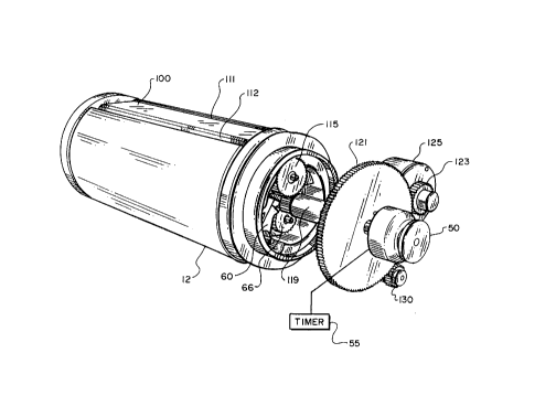
Refer now to FIGS. 3 and 4, which illustrates the primary
3s mechanism of our plate-material supply and uptake apparatus.
With particular reference to FIG. 4, a solenoid armature 50
engages a shaft 52 that passes through a solenoid 54 and
terminates in a linear cam 56. An internal spring (not shown)
-~- 21270:1
urges shaft 52 and armature 50 axially outward from cylinder
12. Cam 56 rests against a linear cam follower 58 such that
linear movement of armature 50 advances shaft 52. (against the
tension of the internal spring) with consequent radial
s displacement of cam follower 58. The necessary movement of
armature 50 may be accomplished manually or, in the preferred
embodiment, by electrical activation of solenoid 54, which
retains shaft 52 in its shifted position. Solenoid 54 is also
connected to a timer 55, which is activated along with solenoid
54 and itself acts to deactivate and disengage solenoid 54
after a preset time has elapsed.
Cam follower 58 extends fxom a pawl 60, which rotates on
a pivot 64. The tooth of pawl 60 engages a ratchet 66 (whose ,
function is described below). A pawl spring 68, extending
is between the arm of pawl 60 and a point within plate cylinder 12
that remains stationary with respect to pawl 60, urges pawl 60 , y
against ratchet 66. Accordingly, the displacement of cam
follower 68 caused by linear movement of shaft 52 and cam 56
counteracts the action of spring 68, releasing pawl 60 from
engagement with ratchet 66.
Refer now to FIG. 5, which illustrates the mechanism by
which plate material is released and taken up. That mechanism
is packaged as a removable, replaceable cassette 100, which
ordinarily resides within the body of cylinder 12 as shown in
zs FIG. 3. Cassette I00 includes a plate-material supply mandrel
105, which is coupled to the shaft 107 of ratchet 66 (see FIG.
4), and a plate material uptake mandrel 110 that engages gear
115 and its integral shaft 116. Thus, when pawl 60 disengages
ratchet 66, supply mandrel 105 is free to .rotate and dispense
30 fresh plate material.
Cassette 100 is introduced into plate cylinder 12 as
shown in FIG. 6, and as more specifically described below.
During operation, plate material from supply mandrel 105
emerges from a space 111 between the top of cassette 100 and
35 the wall of cylinder 12, wraps around cylinder 12 and re-enters
the body of cylinder 12 through an opposing space 112 onto
uptake mandrel 110.
Also as shown in FIG. 5, uptake mandrel 110 is coupled to
an uptake gear 115 by means of integral shaft 116. Uptake gear
{.
v : ".
2~.2~~0:d.
115 ;meshes with a shaft gear 117 coaxial with linear cam shaft
52; shaft gear 117, not shown in FIG. 4 for clarity of
presentation, resides just behind cam 56. As shown in FIGS. 3
and 5, shaft 52 is surrounded by a sleeve 119, which contains
s the internal spring mentioned above, and is also secured to a ~~
large gear 121. Gear 121 meshes with a brake gear 123, which
depends from an electrically controlled brake 125, and also
with a detector gear 130. Detector gear I30 is coupled to a
resettable relay that controls the .current flow to brake 125.
Operation of the plate-winding mechanism of the present
invention may be understood with continued reference to FTGS.
3-6. Ordinarily, shaft 52 rotates 'with cylinder 12 and gear
lI5 remains stationary with respect to shaft 52; gear 121
rotates with respect to gears 123 and 130, which offer no
zs resistance thereto. Axial movement of solenoid armature 50 and
shaft 52 (which axe preferably isolated mechanically from shaft
52 so as to remain conveniently stationary) results in
.,.,
disengagement of pawl 60 and consequent release of supply
mandrel 105, as described above, as well as actuation of timer
0 55 and brake 55. With brake 55 engaged, rotation of shaft 52
and shaft gear 117 is arrested. Cylinder 12 and cassette 100
v~ .
contained therein continue to rotate, however, and with shaft
gear 117 now rendered stationary, rotation of of cylinder 12
causes uptake gear 115 to rotate about shaft gear 117 as a
~s "planet" gear, turning uptake mandrel 110 to draw plate
material from supply mandrel 105 (itself now free to rotate due
to disengagement of pawl 60). A one-way roller clutch (not
shown) prevents reverse rotation of uptake mandrel 110.
The period of timer 55 determines the amount of plate
so material that will be advanced during an uptake cycle. That
period is set such that, at a given rotation rate, just enough
plate material is withdrawn to cover the surface of cylinder
12. When the period of timer 55 expires, reflecting completion
of the uptake cycle, it deactivates solenoid 54, resulting in
ss re-engagement of pawl 60 and ratchet 66 and consequent locking
of supply mandrel 105. Brake 125, however, remains active,
preventing rotation of gears 121 and 117, so that uptake gear
115 continues to turn about shaft gear 117 as cylinder 12 -
-10-
212' 9 0 .~.
rotates. As additional plate material is wound onto uptake
mandrel 110, the tension in the plate material along the
exterior of cylinder 12 increases. This augments the torque on
gear 121 and, consequently, on brake 125 as well. The maximum
s torque on brake 125 is set by the user (e.g., in the case of a
current-limited brake arrangement, by the applied electrical '
current) and, when this torque is exceeded, brake 125 slips and
gear 121 begins to rotate. This is sensed by detector gear
130, resulting in an immediate cutoff of power to brake 125.
io Unimpeded by brake 125, shaft 52 is then free once again to
rotate. The tension established along the plate material is
maintained by the one-way clutch (which prevents material from
leaving uptake mandrel 110) and ratchet 66 and pawl 60 (which
prevent material from being drawn off the supply mandrel).
~s The supply and uptake mandrels can be anchored to the
main plate-cylinder housing in any number of suitable ways. As
shown in FIGS. 5 and 6, in the preferred embodiment they are
contained within a removable cassette 100. A pair of toothed
couplings I50a, 150b connect the supply and uptake mandrels to
zo ratchet 66 and uptake gear 115, respectively, by means of
complementary couplings (not shown) affixed thereto. A series
of orientation pins, which mate with apertures within cylinder
12, ensure proper alignment of these couplings upon
introduction of cassette 100 within cylinder la. Engagement of ',
zs cassette 100 within the body of cylinder 12 is facilitated by
means of circular ramp cam surfaces that act on roller bearings
and permit smooth introduction and locking of cassette 100
after the pins and couplings have been aligned appropriately. ,
The structural elements of cassette 100 are preferably hinged
so together to permit convenient separation thereof and removal of
the supply and uptake mandrels for replenishment.
It will therefore be seen that we have developed a
reliable and convenient mechanism for dispensing and receiving
material that wraps around a cylinder, and which is especially
ss suited to lithographic printing systems. The terms and
expressions employed herein are used as terms of description
and not of limitation, and there is no intention, in the use of
such terms and expressions, of excluding any equivalents of the
y;, : . , :., . : ,. , .... ;. ; . .: . , ;
_ :_ . :., ;; 'v .. ..: . . : . ' . ~ . :~ ':
9A "~ , , ~. .. ., ..,. ~. ... , , v. ; 4 ., .~ . . , . ' .
o .a, ~. ~ ~;; . . . . '~1 ; ; : ' . ',. . A, '~.
. ' :. ,' .~ . ,.~~ "~' ~ " ,~~ .. . , ~ '., '. ..~:~ ,. '~ .:; ; .' ~ , . .'
', . .
.-~ ~~,~,~ , r. .r:.. . .. , , ,. ., '., ' , . . ;~ , : ~ ' ., ,.. '..
,. . ,. - . ..
~m " , .. ~ : ; ..:'.. ,... ,.'~ . .7~.. '., ., ~ w.~ . '. '. '. .~..:~; .,
':,.. y..' .:...~..'.,.' , y:.. ~~ . .'..;: ~: , . '..
-11-
features shown and described or portions thereof, but it is
recognized that various modifications are possible within the
scope of the invent ion claimed. In particular, any number of
metering systems other than a timer can be used to control the
s cycle duration (and, therefore, the amount of material
dispensed from supply mandrel 105); it is possible, for
example, to utilize the output of angular position-sensing
;.
control circuitry already employed to monitor the rotation of
cylinder 12 as a means of gauging the dispensation cycle as
io well, or to use a metering roller within cylinder 12 to
directly measure the amount of material unrolled from supply
mandrel 105. Detector gear 130 can be replaced with other
means of motion detection or a brake assembly designed to
disengage upon slippage; alternatively, a timer can be used to
~s cut off power to brake 115 after a completion of the uptake
cycle.