Note: Descriptions are shown in the official language in which they were submitted.
~VO93/17197 PCT/US93/01923
212~83
DECORATIVE ELEMENTS FOR SUBCEILINGS
This invention relates to subceilings of the type that
utilizes square or xectangular panels supported on a
suspended framework of interconne~ted inverted ~-bar rails
arranged in a series of geometric grid-like patterns, e.g.,
square, rectangular, etc. More paxticularly, this in~ention
relates to decorative elements for covering the bottom
surfaces of the T-bar rails while the panels rest on and are
~ supported on the top surfaces of the T-bar rails.
Backqround
1. Field of the In~ention
~ Subceilings formed from square or rectangular
panels res~ing:~n the top surface~ of horizontally disposed
fl~an~es; of inverted T-bar:rails are well knvwn. Typically,
~a~:ramework~ of~rail~ is:fo~med~with parallel main runners~
su~pended from th~ ceiling above, intersecting with cross
rails~to~provide~a~grid~pattern, usually as ~ f~ x 2 feet
squares;~or~2 f:eet:~x:4~feet ectangles,~ to accommodate
similarly-sized~subceiling panels. In its basic functional
form,~the subc~ilings would have the bot~om surfaces of the
rail~lanyes:expo~ed;~as flat boundary strips between th~
edge supported panel~,
:: : : ~
'
~: :
:::: :
:
: ' ~ SlU~3ST~TUTE SHIElET
WO 93/17197 ~Cl t~3/(~19~3
2127983
For what has become the conventionally styled and
dimensionally standardized version of the inverted T-bar
rail, the industry has developed tight-fitting capping
elements. By cutting and removing a portion of the panel
along its length- ~nd width-extending bottom,edges to
accommodate the thickness of the capped T-bar rails, a
substantially smooth flat bottom surface of the.subceiling
m~y be defined.
It has been an objective to provide the option of
various architecturally-satisfying decorativ~ effects in
suspending ceilings that ha~e exposed flat T-bar flanges in
addition to the mere capping discussed in the previous
pa~agraph. It has also been an objective to provide such
decor~t$ve effects with elements that are designed to be
easily added in place or easily. removed and replaced to
satisfy the cu~tomer's "addiction" to his or her "remodeling
habit".
2. The Prior Art
~ In U.S.~Pat~nt No. 4,848,054, the patentee has
proYi~ed a hollow beam that is readily attachable to the
conventional T-bar~support from below without requiring
add~itional~fastening~h~rdware s~ch as clips or screws. He
.
aileges that his hollow beams are not only useful in new
c~iling installations:but have the~poten~al for convenient
uture~renovation by changing to hollow beams of ~iff~rent
:
2 -
Sa~E35TlTUTE SHIE~T
WO93/17197 2 ~ 2 7 9 ~ PCr/US93/01923
s, ~
size, shape, color or texture without disturbing the support
framework~
It is a similar object of the present invention to
provide beams for capping the inverted T-bar support rails
used in conventional support systems for subceili~gs-that
are readily at~achahle and removable from below without
using any additional fastening hardware.
It is a further obj~ct of the present invention to
provide a beam that is, once in place, constrained from
undesired movement such as skewing or riding upwardly on the
rail flanges.
It is a still ~urther object to pro~ide an element that
is sLmpler and less exp~nsive than the holl.ow beams of the
prior art and displays a substantially greater amount of
versatillty than the hollow beams or the capping elements of
th~ p~or art~
: ~ Summary of the In~en~on
.
~ The ob~:ects of this invention are accompli~hed by a
:~ ~decorati~e capplng beam for coveri~g the inverted ~ee-bar
(T-~ar) panel support rail comprisin~:
a flat port1on; ~
:
~ a~fi~rst return flange di~posed along one upper edge of
,
' the~flat por~ion in~egral ~herewith and ex~ending inwardly;
a second return f lange dispc)sed along a s~cond upper
edge of the flat portion integral therewith and extending
inwardly;
- 3 -
~:
SU~3~;T3TUTE S~ E~
W093/17197 ~. ~ P~T/US93/~t~23
21279~3
each of said return flanges having a downward-facing
surface and an inwardly facing edge;
at least one, but preferably onel vertically extending
structural element from the bottom surface of the flat
portion and integral at its upper surface with the bottom -
surface of the flat portion;
a decorative element attached ~o, or integr.al with, the
bottom surface of the vertically extending structural
element, the decorative element preferably extending
horizontally~
In simple terms, the invention is the combination of a
tee shaped ceiling support grid to which dimensional
~ecorative elements are applied. The elements snap on the
face of ~he grid via resilient hooked arms. The anms are
. --
: . connected by a web which lies against the face of the tee
shaped grid when engaged. Perpendicular to this face is
,: ,
preferably~a~:single~vertlcal member which connects the
decorative por~ion of the element to th~ web. ~he snap-on
: feature,:therefore, is not necessarily integral with ~he
:,
ecorative:feature.~ Thus,~the decoratlve feature is no~
restr~cted:in~ siz :or ~hape by the:attachment mQchanism or
,
by :the tee grid.~ In addition, the dlmensional element can
é snapped onto the~grid with ease. Pressure exerted on th~
;; face of:the~eleme~t is trans~erred through the vertical
member. The force is then equally transfexred to both
resilient hooked a~ms. By having the arms free frc)m the
?
~ 4 -
~ ~ .
5~ UTE !~;~E~
W093/17197 PCT/US93/01923
2127~3 .
vertical memher, they are able to flex freely around the
grid face and engage simul~aneously. No "rocking" of the
element against the face of the grid is necessary to attach
the profile to the grid. The dimensional element may be
either factory or field applied. Having a u~i~ersal-shape
~ for the attachment portion, regardless o~ the decorative
face, lends itself to automated assembly. No mat~er what
the design of the profile may be, the consistency of the
attachment portion provides a place to capture the part for
robotic assembly.
The dimensional element may be extruded, molded, or
machined from plastic, wood, metial, composite materials or
any material wlth sufficient flexibility as a thin member to
allow the element to snap over ~h~ te~ grid. Preferred is a
material wlth low thermal expansion (Coefficien~ of Therma
Expansion ~f .le~s than or equal to 3.0 x 10⁻⁵ in/in~F)
similar ~o the grid. In this way, the dimensional element
.
does not move~, warp, or gap wi~h changes in sm~ient
te~perature once it is applied to th~ g~id.
TAis in~ention will bring a new eas~ to de~igning a~d
~; ~ rnanufactllring gri ~. Metal roll forming, which is typically
used to ~produce grid, would have rsquired a new xoll fQrming
mill for each design de~irèd on the grid face. A new mill.
: i~ a c05tly inv~stment. To change ~rom one design product
to:another would be quite expensive and time consuming.
With the present inventionl new roll formers are no lsnger
- 5 -
.
~:
SU~t5T~TUTE SHEEll'
WO93/17197 PCT/US93/01923
212798~ i:
required since no change is made to the grid. To change the
appearance of the grid using the present invention, one
simply applies a different dimensional element to the tee
grid. The saving of time~ money and effort is substantial.
FurthermoreJ by using a method other thqn-roll forming
permits the formation of complex designs for the decorative
element. This flexibility, in turn, lends itseLf to
creating visually integrated ceiling system~. The ceiling
board could be cut to complement the decorated grid
visually.
Also, the elements of this invention could be designed
to be compatible wlth tegularized ceiling board edge d~tails
as well as with flush:panels. For larger dimensional
elements ex~endlng~beyond the face of the tee grid, the
ceil~ng board could be specially~ut along its edge so that
the board may:rest on the tee shaped ceillng support grid.
hLs~ ynergy~of~:~the celling and grid greatly enhances the
overall~appearance of an~accessible ceiling. Alternatively,
the b~ard~could~be cut to~rest~ on~ the ~dimensional element
directly.~
A~critic~a~l e;lement~of a~ceillng~susp~nsion system is
th~in~ersectio~:~of: m~mbers: that:are~perpendicular to one:
ano~her,~'e~g.~, where:four ceillng boards meet. To
accommodate any~profile that the dimensional element might
have, the~present invention~may utilize a double miter at
the~end:o~ ~ach~profile in the intersection. This feature
6 -
:
SU~STITUTE SHEE~
., . . ... . . . ~ .... ., ~, ...
WO93/171~7 PCT/US93/01923
~12~i3
is profile independent, thus providing a universal
intersection. In addition, the appearance is tailored and
identical at each intersection in the ceiling. No further
notching o~ the dimensional element is required, either at
the fac~ory or on the job.site, to allow clearance~for the
intersection of the support grid. The underlying tee shaped
grid may still intersect in a flush manner as is typical for
this type of suspension system, but this unattractive
intersection would not be visible from the room below since
the mitered dimensional elements would cover it.
The advantages of the present inven~ion may ~e
sum~arized, aa follows:
1. It uses less material than the hollow beam of U.S.
Pakent No. 4,722,l6l;
2. Since~the~attachment ~echanism may not be integral
with the v~rtical member, it is easier to snap the element
ont~ the t~e~grid~(no "rocklng" i8 required to engage);
3. The d~orati~e face does not have to be the same
slze a~~the tee~grid:face; ~
4. ~The flexibility of design allows coordination
etwe~n the design~o~f~the ceiling board with the~design of
the~dimensional element resul~ing in a dis~inc~ improvement
in accessible:;ceiling~appeàrance;
5. By~using~hermally stable material ~o ~ake the
element permits i~s application in the~fac~ory, a~ well as
on site, wi~hout the::dimensional elements i'drifting" on the
: - 7 -
:.
SUE3!!3T~TIJ~E ~ EE~
WO 93/1 71 97 : ! ' PCl'/~lS93/01 923
2127983
tee grid due to exposure ~o changes in temperature during
shipping or at the installation site;
6. The double mitered intersec~ion will reguire no
notching of the invented element to accommodate the
underlying tee grid inter ection; in addi~io~, ~he double
miter will provide an improved, tailored appearance.
Brief Description of the Drawinqs .
The invention will be more clearly understood by
referring to ~he drawings and the detailed description that
follows. ~ :
: In the drawings:~ ~
Figure 1~is a cross-sectlonal view of a beam of this
invention in a~ initi21 position in the pr~cess of being
:
: installed onto a conven~ional inverted T-bar rail;
Figure 2 i~8 ~a cross-sectional view of ~he beam shown in
iguxe l ~fter in~tal:lation on the T-bar rail;
Figure:3 i8~ a cro~s-sectional view of ~ beam installed
on :a T-~ar rail:, alo~g with subceiling~panels in place, the
. , ,
beam~having.:~a~specially deslgned decoratlve element integral
therewith; ~
Figure~ 4~ 6~a;~:bottom view of: the :~ubceiling at the
mitered intersection~of four beams~ each of which i~ shown
ross-section in Figure 3;
Figure 5;~is;~:a top view, in~perspective, of the mitered
intersection of~ two~ru ner beams~ and two cross beams of
Flgures 3 and~4; and :: ~
Sl 8B~ 1 1 I VTE SI~E~ET
wo 93/17197 2 1 2 7 9 8 3 PCT/US93/~19~3
L~ ~ K IYY~
Figures 6-22 are cross-sectional views of beams having
a variety of specially designed decorative elements.
Detailed Description
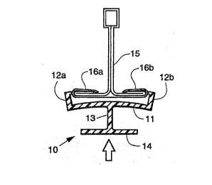
Fi~ure l is a cross-sectional view.showing the
configuration of a beam 10 constructed in acçordanc~ with
the present invention. Beam 10 is basically composed of
three associated elements: the decorative element 14,
integrated through ~or attacned to) a vertically disposed
connecting element l3 which may be integral with, or
attached to, the substantially resilient fastening element.
The fastenlng element is composed of a substantially
horizontal flat or f~ace portion ll adapted to contact the
outer surface of ~the ~-bar: and having hooked arms or return
;:
flanges~l2a and 12b~along each upper edge integral with the
face portion 11 and extending inwardly.
Beam lO: may~b~fabricated from metal,: wood~ e~c., but
pref~rably~it i~fab-icated~fro- a flexible tough plastic
such~a9:polyproplylene,~ high d~nsity polyethylene, an acrylic
copolymer:or~homopol~mer,:etc. ~ :
In~Figure l,~;~beam~;lO is ~shown w1th~the hooked a ~ ~ or
re~urn~flanges 12a~and~:12b flexed outwardly as the beam is
being for~d~o~ver~:th:e;~rolled::flanyed~edges~ l6a and~ I6b~of~
the~;"T-bar~,rail"~l5.~ The in~erted~T-bar rails co~prise the
framëwork~susp~ndéd~in a~grid pattern to suppor~ the square
or~ ectangular~panels that form the ceiling. They represent
e~ ie i~V~rt~d~T-bar ra11s 15 chat are cu~rencly sed
S~i3STlTUTE SH EET
W093/17197 . . ; PCT/US93~01923
. .
2127983
for both residential and commercial ceilings. The support
wires, that serve to suspend the rails by being looped
through an opening in the rails and then connected to the
building structure above, are not shown. A relative1y mild
force applied by hand, as indicated by the a~row, holds
return flanges 12a and 12b upwardly against the sides of the
edges of flanges 16a and 16b, respectively.
Figure 2 shows the beam 10 in its installed position.
By continuing to apply the mild pressure, the return flanges
or arms 12a and 12b ul~imately snap over and rest on the
flanges 16a and 16b and the flat portion 11 fits snugly
against ehe outer surface of the "T" of the T-bar rail 15.
Flat portion 11 acts as a strike plate to constrain any
skewing or other movement of the beam 10.
In Figure 3, the end portions of ceiling panels 17a and
-
17b are shown ln plaee resting on return flangçs 12a and 12b
wi;th the decorative element 14 of beam 10 serving to provide
a~covering for the~usually metal sur;face of the T-bar rail
15~ The finaL r~sult is a smooth,: visually effective
ceiling. Various de~ign elements~associated with the other
wo~:ba~lc elements~are~shown in Figures 6 through 22. It
wi:ll:b@ no~ed~that:~he connecting element:13 may extend from
the;;flat portion 11 of the faste~ning-element to a level
wh:e~re~the decorative element is ~elowl above, or a~ the same
lev:~l:a~s the~exposed surface of the ceiling panel.
: ~ ~: : : : :: :
10-
SI~BSTITUTF 5HEET
W~93/17197 2~ 2 79~ 3 PCT/US93/01923
. - ':, .,. ~
Figure 4 is a bottom view of the subceiling composed of
ceiling panels l8 and mitered beams having the decorative
elements l4 shown in Figure 3. Figure 5 is a top view of
the four intersecting mitered beams shown in Figure 4. It
will be noted that although they are not shown, the Inverted
T bar rails used as runners and cross members may be the
standard "unmi~ered" rails currently employed fo~ the
suspended framework that constitutes the grid~
:
: :
S:U8$TITUTE SHE~