Language selection

Search

Patent 2128010 Summary

Third-party information liability

Some of the information on this Web page has been provided by external sources. The Government of Canada is not responsible for the accuracy, reliability or currency of the information supplied by external sources. Users wishing to rely upon this information should consult directly with the source of the information. Content provided by external sources is not subject to official languages, privacy and accessibility requirements.

Claims and Abstract availability

Any discrepancies in the text and image of the Claims and Abstract are due to differing posting times. Text of the Claims and Abstract are posted:

  • At the time the application is open to public inspection;
  • At the time of issue of the patent (grant).
(12) Patent Application: (11) CA 2128010
(54) English Title: AN ELECTRO-ACOUSTIC TRANSDUCER
(54) French Title: TRANSDUCTEUR ELECTRO-ACOUSTIQUE
Status: Dead
Bibliographic Data
(51) International Patent Classification (IPC):
  • H04R 9/10 (2006.01)
  • H04M 1/03 (2006.01)
  • H04R 11/06 (2006.01)
(72) Inventors :
  • EWENS, STUART C. (United Kingdom)
(73) Owners :
  • KNOWLES ELECTRONICS CO. (United Kingdom)
(71) Applicants :
(74) Agent: OSLER, HOSKIN & HARCOURT LLP
(74) Associate agent:
(45) Issued:
(86) PCT Filing Date: 1993-11-30
(87) Open to Public Inspection: 1994-06-23
Examination requested: 2000-11-23
Availability of licence: N/A
(25) Language of filing: English

Patent Cooperation Treaty (PCT): Yes
(86) PCT Filing Number: PCT/GB1993/002457
(87) International Publication Number: WO1994/014292
(85) National Entry: 1994-07-13

(30) Application Priority Data:
Application No. Country/Territory Date
9225650.2 United Kingdom 1992-12-04

Abstracts

English Abstract

2128010 9414292 PCTABS00032
This invention relates to electro-acoustic transducers such as is
generally indicated at (10) and which comprise a body (11)
defining a chamber (12), a plate (13) bearing a microphone or speaker
(14) to which is attached a stalk (15), a diaphragm (16),
connectable to the stalk (15), which extends substantially across the
chamber (12), an end piece (17) and an end cap (18). The end piece
(17) has a kidney-shaped recess (21) which provides the main
communication path between subsidiary inlets/outlets (19) and a main
inlet/outlet (20). When the channel (22) is closed off by the end
cap (18) it is effectively in the form of a tube and constitutes
a Thuras tube. The length of this path effectively creates a
long discharge path between the wearer's ear and any earthable metal
part within the transducer and hence protects against electric
shock.


Claims

Note: Claims are shown in the official language in which they were submitted.


WO 94/14292 PCT/GB93/02457


Claims
1. An electro-acoustic transducer including a body
defining a chamber, a diaphragm extending across at least
part of the chamber to define front and rear portions, a
main acoustic inlet/outlet connected to the front portion
and a Thuras tube connecting the rear portion and the main
inlet/outlet, wherein at least a portion of the tube is
defined by an end piece forming a wall of the chamber.
2. A transducer, wherein in the end piece further
defines the main acoustic inlet/outlet.
3. A transducer as claimed in Claim 1 or Claim 2,
wherein the tube Thuras is in the form of a channel formed
in the end piece.
4. A transducer as claimed in any one of Claims 1 to
3, further including a cap overlying the end piece with
subsidiary inlets/outlets formed therein offset from the
main inlet/outlet.


5. A transducer as claimed in Claim 4 as dependent on
Claim 3, wherein the end cap closes off the channel to form
the Thuras.

6. A transducer as claimed in Claim 4 and Claim 5,
wherein the end cap and end piece together define an
extended air path between the subsidiary inlet/outlet and an
earthable metal part within the chamber.

7. An electro-acoustic transducer having a chamber
including an earthable metal part therein, a non-electrical-
ly conducting cover defining a number of subsidiary acoustic
inlets/outlets and a main acoustic inlet/outlet for the


WO 94/14292 PCT/GB93/02457


chamber, wherein the cover defines an extended air path
between the subsidiary outlets and the earthable metal part.
8. A transducer as claimed in Claim 7, wherein the
chamber is generally cylindrical, the main inlet/outlet is
at or adjacent the axis of the chamber; the subsidiary
inlets/outlets are radially offset therefrom and the main
inlet/outlet is defined in a wall extending across the
chamber.
9. A transducer as claimed in Claim 8, wherein the
subsidiary inlets/outlets are formed in an end cap which
overlies the wall and a part of the air path is defined
between the air cap and the wall.

Description

Note: Descriptions are shown in the official language in which they were submitted.


WO 94114292 2 ~ 1 O PcT/GB93io24s7 : ~


..
AN ELECTRO-ACOUSTIC TRANSDUCER
i, .. ..
This invention relates ~o electro-acoustic transducers
and particularly, but not exclusively, to such transducers
in the form of earpieces for telephone headsets and the
I S like.
Telephone operators often build up very s~ubstantial
static voltages on their bodies, particularly if they are
imprudent enough to wear man-made fibres. If they then plug
their headset into the telephone exchange apparatus lt is
not uncommon for a spark to jump from their ear through the
acoustic~lnlets in the earpiece to an earthed metal portion
of the t.ransducer. ~As these sparks can be derived from
. ...
several thoùsands of volts the sensation is at best
uncomfortable. This problem particularly arises in small
devices where the distances between the acoustic inlets and
ea~rthable;portions o~ transducers are normally extremely
;~ ~ small.~ Additionally, lt has been found difficult to produce
economically and~compactly~a suitable method of boosting the
bass;~response~of such earpieces.~
~ The object of the invention i 5 to miti~ate oAe or both
of the~se~problems~
From one aspect the invention consists in an electro-
acoust~ic~transducer including a body deflnlng a chamber, a
diaphragm extending across at least part of the chamber to
define front and rear portions, a main acoustic inlet/outlet
connected to the front portion and a Thuras tube connecting
:
~,
`:
: :,
~: : '
slles~lTc~ ~ F~ - ~

WO94/14292 PC~/GB9310~57

2 1 2 ~ 2 ~ ~

the rear portion and the main inlet/outlet wherein at least
a portion of the tube is defined by an end piece forming a
wall of the chamber.
In a preferred embodiment the end piece further defines
the main acoustic inlet/outlet and the tube may be formed as
a channel in that end piece~ Particularly conveniently the
transducer may further include a cap overlying the end piece
with subsidiary inlet/outlets formed therein and offset from
..., . , :
the main inlet/outlet. In this case the end cap may close
lO off the channel to complete the tube. ~ ;
The end cap and end piece may together define an ~
~ ,:, :
extended air path between the subsidiary inlet/outlets and
an earthable metal part within the chamber. Current designs
simply have these inlets and outlets passing straight
through the cap into the chamber, although sometimes there
are guards to prevent mechanical damage due to penetration
through these holes. ;
From another aspect there is provided an electro~
acoustic transducer having a chamber including an earthable
20 metal part, a non-electrically conducting cover defining a ~ -
number of subsidiary acoustic inlet/outlets and a main -
, ~ -,
acoustic inlet/outlet for the chamber wherein the cover~
defines an extended air path between the subsidiary outlets ~-
and an earthable metal part within.
. .. . . ...
As has been mentioned above this extended path reduces
the risk of electrical discharge occurring along the path
typically for potential differences of up to 15,000 volts
D.C.
~ .
SlJBST5TUTE SHEET

WO~4/14292 2 ~ PCTIGB93/0~57
', . '~ .~ ~,
3 -

Preferably the chamber is generally cylindrical, the
main inlet/outlet is at or adjacent the axis of the chamber,
the subsidiary inlets/outlets are radially offset therefrom
and the main inlet/outlet is defined in the wall extending
across the chamber.
Particularly conveniently the subsidiary inlets/outlets
are formed in an end cap which overlies the wall ànd a part
of the air path is defined between the air cap and the wall.
Although the invention has been defined it is to be ~ ~10 understood it includes any inventive combination of the - ; features set out above or in the following descriptio~.
The invention may be performed in various ways and a
specific embodiment will now be described, by way of
example, with reference to the accompanying drawings, in
which~
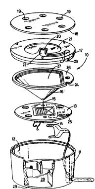
Figure 1 is an exploded view of an electro-acoustic ~transducer; ;
Figure 2 is a more detailed view from above of an end
piece of the transducer, and
Figure 3 is a diagrammatic cross-sectional view of the
upper part of the transducer demonstrating a discharge pàth. ~ -~
An electro-acoustic transducer is generally~indicated
at 10 and comprises a body 11, defining a cham~er 12, a
plate 13 bearing a microphone or speaker 14 to which is
attached a stalk 15, a diaphragm 16, connectable to the
stalk 15, which extends substantially across the chamber 12, ;
an end piece 17 and an end cap 18.
The end cap 18 defines a number of spaced subsidiary
-

~ W094/14292 PCT/GB9310~57
2~28~
~..~

acoustic inlets/outlets 19, through which sound may pass
either to or from a main acoustic inlet/outlet 20 defined in
the end cap 18. This inlettoutlet 20 communicates directly
with the diaphragm 16 and hence via the stalk 15, with the
S microphone 14.
It will be noted that the end piece 17 has a kidney~
shaped recess 21, which provides the main communication path
,,
between the subsidiary inlets/outlets and the main
inlettoutlet 20. A channel 22 projects into this recess 21
to extend from the main inlet/outlet 20 to a vertical shaft
23 which extends through the thickness of the end cap 18 to
communicate with aligned notches 24,25 in the diaphragm
support 26 and the plate 13.
It will thus be seen that the main inlet/outlet 20
communicates both with a front portion 27 of the chamber 12
contained within the diaphragm 16 a~d a rear portion 28
de~ined between the base 29 of the body 11 and the plate 13.
As the end cap 18 is shaped so that it closes off the upper
mouth of the channel 2Z, the channel 22 is effectively in
the form of a tube and constitutes a Thuras tube providing
bass resonance or reinforcement from the rear portion 28 of
~the chamber 12.;
This construction is particularly compact; economic to
~make and easy to assemble.
.
As has been mentioned above, many traditional earpieces
for headsets, and indeed other transducers, have the sound -
inlets passing simply through the end cap 18 and the ~end
.
piece 17 does not exist. This means that there is a very ~ ~

. .
~ ST~Te 9TI~ S~ET :: :

W094/1~92 21 2 8 ~ 1 ~ PCT/GB93/0~7

~

short discharge path between a wearer's ear and any
earthable metal part within the transducer, such as the
diaphragm support 26.
Referring to Figure 3, it will be seen that the
interposing of the end piece 17 and the provision of a
central main acoustic inlet/outlet, has the effect of making
a considerably extended air path between the ear (here
represented as an electrode 30) and the metal part 31. The
result is that very high voltages, say typically 14,000 or
15,000 volts D.C. have to be built up before a spark will
jump along a path of this length. Clearly, in order for
this aspect of the invention to operate, the end piece 17
and end cap 18 must be electrically insulating.
It will be appreciated that the provision of both of
the extended air path and the Thuras tube in the end
piece/end cap combination is particularly effective in
producing a much improved transducer at low additional cost.
Although these advantages have been particularly
demonstrated in connection with earpieces, they are equally
applicable to any transducer use in which large D.C.
voltages are likely to occur adjacent the sound
inlet/outlets.
:

'~:'


9 ~ 1~ F .~:; ~ F ~

Representative Drawing
A single figure which represents the drawing illustrating the invention.
Administrative Status

For a clearer understanding of the status of the application/patent presented on this page, the site Disclaimer , as well as the definitions for Patent , Administrative Status , Maintenance Fee  and Payment History  should be consulted.

Administrative Status

Title Date
Forecasted Issue Date Unavailable
(86) PCT Filing Date 1993-11-30
(87) PCT Publication Date 1994-06-23
(85) National Entry 1994-07-13
Examination Requested 2000-11-23
Dead Application 2003-12-01

Abandonment History

Abandonment Date Reason Reinstatement Date
2002-12-02 FAILURE TO PAY APPLICATION MAINTENANCE FEE
2002-12-23 R30(2) - Failure to Respond

Payment History

Fee Type Anniversary Year Due Date Amount Paid Paid Date
Application Fee $0.00 1994-07-13
Registration of a document - section 124 $0.00 1995-01-03
Maintenance Fee - Application - New Act 2 1995-11-30 $100.00 1995-11-29
Maintenance Fee - Application - New Act 3 1996-12-02 $100.00 1996-11-13
Maintenance Fee - Application - New Act 4 1997-12-01 $100.00 1997-11-19
Maintenance Fee - Application - New Act 5 1998-11-30 $150.00 1998-11-13
Maintenance Fee - Application - New Act 6 1999-11-30 $150.00 1999-11-16
Request for Examination $400.00 2000-11-23
Maintenance Fee - Application - New Act 7 2000-11-30 $150.00 2000-11-23
Maintenance Fee - Application - New Act 8 2001-11-30 $150.00 2001-10-16
Owners on Record

Note: Records showing the ownership history in alphabetical order.

Current Owners on Record
KNOWLES ELECTRONICS CO.
Past Owners on Record
EWENS, STUART C.
Past Owners that do not appear in the "Owners on Record" listing will appear in other documentation within the application.
Documents

To view selected files, please enter reCAPTCHA code :


To view images, click a link in the Document Description column. To download the documents, select one or more checkboxes in the first column and then click the "Download Selected in PDF format (Zip Archive)" or the "Download Selected as Single PDF" button.

List of published and non-published patent-specific documents on the CPD .

If you have any difficulty accessing content, you can call the Client Service Centre at 1-866-997-1936 or send them an e-mail at CIPO Client Service Centre.


Document
Description 
Date
(yyyy-mm-dd) 
Number of pages   Size of Image (KB) 
Claims 1995-07-29 2 67
Representative Drawing 1998-07-24 1 15
Cover Page 1995-07-29 1 17
Abstract 1995-07-29 1 61
Drawings 1995-07-29 2 61
Description 1995-07-29 5 213
Assignment 1994-07-13 7 271
PCT 1994-07-13 2 104
Prosecution-Amendment 2000-11-23 1 58
Prosecution-Amendment 2002-08-23 2 50
Fees 2000-11-23 1 54
Fees 1997-11-19 1 57
Fees 2001-10-16 1 53
Fees 1998-11-13 1 58
Fees 1999-11-16 1 55
Fees 1995-11-29 1 81
Fees 1996-11-13 1 93