Note: Descriptions are shown in the official language in which they were submitted.
2128383
TITLE OF THE INVENTION
OUTBOARD ENGINE STRUCTURE
BACKGROUND OF THE INVENTION
Field of the Invention:
The present invention relates to an outboard engine
structure having an oil pan accommodated inside an extension
case.
Description of the Prior Art:
Outboard engine structures with a four-stroke cycle
engine mounted thereon are grouped into two types: one having
its oil pan formed integrally with one of outer wall defining
members of the outboard engine structure such as an extension
case; and another having an oil pan formed separately from
such outer wall defining member and accommodated inside the
latter.
Japanese Utility Model Application Laid-open No.
X19199/91 (No. 3-49199) has made known an outboard engine
structure of the type wherein an oil pan is formed separate
from an extension case and accommodated within the case. In
this known engine structure, a recess portion is formed at
the rear of the extension case and a drain passage for the oil
pan is exposed to the recess portion. Draining of oil is
conducted by drawing off a bolt mounted within the recess
portion.
When casting an extension case used in an outboard
engine structure from aluminum alloy material, it is general
- 1 -
70488-60 2 1 ~ 8 3 8 3
that a casting die is formed of two die parts which are divided
into left and right sides. In case of the aforementioned
conventional outboard engine structure, however, the recess
portion formed at the rear of the extension case has left and
right side walls and is opened rearwardly, so that a rear side
die part is required in addition to the left and right side die
parts, this providing a problem that die parts must be divided
in a complicated fashion and hence it results in a high cost.
Moreover, since the recess portion is provided at the
rear of the extension case, it cannot be directed toward the
ship body side even after steering the outboard engine
structure to the maximum so that the operation of draining oil
is difficult to be done from an on-board position.
Furthermore, if a tool is used to loosen the drain bolt for
draining of the oil from the oil pan, the tool may undesirably
be contaminated with the oil discharged through a bolt hole.
SUMMARY OF THE INVENTION
The present invention has been proposed in view of
the above circumstances to provide an outboard engine structure
whose extension case can easily be molded. It is also desired
to provide an outboard engine structure in which the operation
of removing oil from the oil pan is conducted easily.
The invention provides an outboard engine structure
comprising an engine, a case for carrying said engine on an
upper portion thereof, an oil pan which is accommodated inside
an extension case forming at least a part of said case and
stores oil for lubricating said engine, a drain passage for
draining the oil from said oil pan, a drain passage opening and
closing means for opening and closing said drain passage, and a
pair of left and right mounts for carrying said extension case
on a swivel case against vibration, wherein a mount receiving
recess for receiving at least a part of one of said left and
right mounts and an oil drain recess to which said drain
2
X0488-60 2 1 2 g 3 8 3
passage opening and closing means is exposed are formed
adjacent to each other and opened in the same direction on a
side surface on one of left and right sides of said extension
case, and wherein said oil drain recess and said mount
receiving recess for said one of the left and right mounts are
disposed adjacently to each other in a vertical direction with
a common partition wall interposed therebetween.
Owing to the above arrangement, a casting die used
for casting the extension case can be formed of two die parts
which are divided into left and right sides and the mount
receiving recess and the oil drain recess can be formed
simultaneously in a casting process by using one of the parts.
Moreover, if the outboard engine structure is steered, the oil
drain recess which is formed on one side surface of the
extension case is directed toward the ship body side so that
the drain passage opening and closing means can be operated
from an on-board position to complete the oil draining
operation. During this operation, the oil drain recess can be
directed downwardly by tilting up the outboard engine structure
whereby the oil can swiftly be discharged to the outside
without permitting the oil to be adhered to the outboard engine
structure.
Furthermore, according to the invention, there is
provided an outboard engine structure comprising an engine, a
case for carrying the engine, an oil pan for storing oil, and a
drain passage for draining the oil from said oil pan, and a
drain passage opening and closing means for opening and closing
said drain passage, wherein an oil drain recess is formed in
said case in an inwardly recessed manner, and an operating
portion for operating said drain passage opening and closing
means is disposed inside said oil drain recess at a position
remote from a path through which the oil to be drained from
said drain passage flows.
3
70488-60 2 ~ 2 8 3 8 3
With the above arrangement, when the operating
portion is operated to release the drain passage opening and
closing means for draining of the oil, a tool is not
contaminated with the oil to be discharged through the drain
passage, this contributing to enhancing the working efficiency.
The invention also provides an outboard engine
structure comprising an engine, a case for carrying said engine
on an upper portion thereof, an oil pan which is accommodated
inside an extension case forming at least a part of said case
and stores oil for lubricating said engine, a drain passage for
draining the oil from said oil pan, a drain passage opening and
closing means for opening and closing said drain passage, and a
pair of left and right mounts for carrying said extension case
on a swivel case against vibration, wherein a mount receiving
recess for receiving at least a part of one of said left and
right mounts and an oil drain recess to which said drain
passage opening and closing means is exposed are formed and
opened in the same direction on a side surface on one of left
and right sides of said extension case, and wherein said oil
drain recess is formed within a range of a width of said mount
receiving recess for said one of the left and right mounts in a
front-and-rear direction as seen in a side view.
The invention further provides an outboard engine
structure comprising an engine, an oil pan for storing oil
lubricating said engine, a drain passage for draining the oil
from said oil pan, and a drain passage opening and closing
means for opening and closing said drain passage, wherein an
operating portion for operating said drain passage opening and
closing means is disposed at a position remote from a path
through which the oil to be drained from said drain passage
flows, wherein an extension case is provided which is to be
carried on a ship body by means of a pair of left and right
mounts in such a manner that the extension case is capable of
tilting up and down and being steered to left and right,
4
70488-60 ~ ~ 2 8 3 8 3
wherein said drain passage is disposed in an oil drain recess
which is formed on a side surface on one of left and right
sides of said extension case while a mount receiving recess is
formed on said side surface of said extension case for
receiving at least a part of one of said pair of mounts.
The invention further provides an outboard engine
structure comprising an engine, a case for carrying said engine
on an upper portion thereof, an oil pan which is accommodated
inside an extension case forming at least a part of said case
and stores oil for lubricating said engine, a drain passage for
draining the oil from said oil pan, a drain passage opening and
closing means for opening and closing said drain passage, and a
pair of left and right mounts for carrying said extension case
on a swivel case against vibration, wherein a mount receiving
recess for receiving at least a part of one of said left and
right mounts and an oil drain recess to which said drain
passage opening and closing means is exposed are formed and
opened in the same direction on a side surface on one of left
and right sides of said extension case, said mount receiving
recess and said oil drain recess being formed in an inwardly
recessed manner from a plane defined by said side surface of
the extension case.
The invention further provides an outboard engine
structure comprising an engine, a case for carrying said engine
on an upper portion thereof, an oil pan which is accommodated
inside an extension case forming at least a part of said
carrying case and stores oil for lubrication of said engine, a
drain passage for draining the oil from said oil pan, a drain
passage opening and closing means for opening and closing said
drain passage, and a pair of left and right mounts for carrying
said extension case on a swivel case against vibration, wherein
a mount receiving recess for receiving at least a part of one
of said left and right mounts and an oil drain recess to which
said drain passage opening and closing means is exposed are
4a
=E.-~~.,,,
70488-60 2 1 2 8 3 8 3
formed adjacent to each other and opened in the same direction
on a side surface on one of left and right sides of said
extension case.
The above and other features and advantages of the
present invention will become apparent from the following
description of preferred embodiments taken in conjunction with
the accompanying drawings.
Incidentally, the expressions "front", "rear",
"front-and rear direction" and the like terms used herein
should be understood to be in alignment with the front and rear
direction of the ship body or hull to which an outboard engine
structure is associated and mounted in use.
BRIEF DESCRIPTION OF THE DRAWINGS
4b
,__.__ 2128383
Figs. 1-3 show a first embodiment according to the
invention, in which Fig. 1 is a whole side view of the
outboard engine structure, Fig. 2 is an enlarged sectional
view taken along a line 2-2 in Fig. 1 and Fig. 3 is a
sectional view taken along a line 3-3 in Fig. 2.
Figs. u-8 show a second embodiment according to the
invention, in which Fig. 4 is a whole side view of the
outboard engine structure, Fig. 5 is an enlarged sectional
view taken along a line 5-5 in Fig. 4, Fig. 6 is a sectional
view taken along a line 6-6 in Fig. 5, Fig. 7 is a sectional
view taken along a line 7-7 in Fig. 6 (with a gear case 10
being omitted therefrom) and Fig. 8 is a sectional view taken
along a line 8-8 in Fig. 5.
DESCRIPTION OF PREFERRED EMBODIMENTS
A first embodiment according to the invention will first
be described hereinafter with reference to Figs. 1-3.
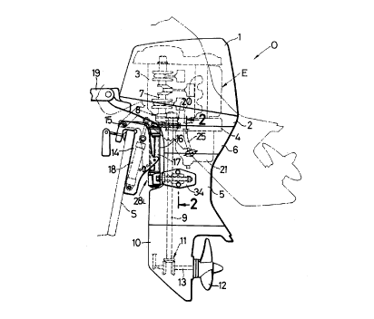
As shown in Fig. 1, an outboard engine structure 0 has a
vertical type three-cylinder engine E mounted at an upper
portion thereof. Upper and lower portions of the engine are
covered with an engine cover 1 and an under case 2 which are
provided separable from each other. To a lower surface of an
engine block 3 is connected, via a joint member u, an upper
surface of an extension case 5. The extension case 5 is
covered its upper portion with an under cover 6 which is
carried on a lower portion of the under case 2. The engine E
has a crankshaft 7 which is connected at a lower end thereof
- 5 -
2128383
with a drive shaft 9 via a reduction mechanism 8. The drive
shaft 9 extends downwardly inside the extension case 5 and is
connected, via a bevel gear mechanism 11 disposed inside a
gear case 10, to a propeller shaft 13 which has a propeller 12
at a rear end thereof. The mentioned under case 2, joint
member 4, extension case 5 and gear case 10 together form a
case according to this embodiment.
A stern bracket 14 is detachably fixed to a ship body or
hull S and a swivel case 16 is pivoted to the stern bracket
14 via a laterally extending tilt shaft 15 for vertical
swinging motion. The outboard engine structure 0 is pivoted
to the ship body S for lateral swinging motion by means of a
swivel shaft 17 which extends vertically through the swivel
case 16. The outboard engine structure 0 is accordingly
capable of tilting up from a solid line position to a chain
line position by driving and expanding a cylinder 18 which is
mounted between the stern bracket 14 and swivel case 16. The
outboard engine structure 0 is further capable of being
steered to the left and the right by operating a steering
lever 19 provided on the under case 2.
As apparent from additional reference to Figs. 2 and 3,
the extension case 5 and an oil pan 21 are fixed to a lower
surface of the joint member 4 via bolts 22.., 23..,
respectively. The oil pan 21 is fitted inside the extension
case 5 such that it is offset from a center line CL of the
extension case 5 toward one lateral side (right side in Fig.
2), and in a space provided on the other side, i.e., left
- 6 -
2128383
side, there is disposed an exhaust pipe 2u which is connected
at its upper end to an exhaust passage ~, formed in the
joint member 4 and an exhaust passage 21, formed integrally
in a bulged portion of a mounting flange of the oil pan 21
and which opens at its lower end to the interior of the
extension case 5. The exhaust gas which is discharged from
the exhaust pipe 2u to the inside of the extension case 5 is
passed through a hollow interior of the propeller 12 into the
water. An oil supply pipe 25 for supplying oil to the engine
E and an oil returning pipe 26 for returning oil from the
engine E are opened to the inside of the oil pan 21 and a
strainer 27 is provided at the lower end of the oil supply
pipe 25.
The swivel shaft 17 which is fitted inside the swivel
case 16 is carried resiliently at its upper end on the joint
member 4 via an upper mount 20 and at its lower end on left
and right side surfaces of the extension case 5 via a pair of
left and right lower mounts 28~, 28a. The lower mounts 28
~, 28R comprise a stay 29 spline-connected to the lower
end of the swivel shaft 17, a pair of bolts 30~, 30R
extending through left and right side portions of the stay 29
in the front-and-rear direction, and rubber bushes 32~, 32
R which are fitted over outer peripheries of the bolts 30~,
30R via collars 31~, 31a.
One rubber bush 32~ on the left side is fitted in a
mount receiving recess 5,~ which is formed on the left side
surface of the extension case 5 and the opening defined by the
- 7 -
' 2128383
recess 5,~ is covered with a left cover 34 which is fixed
to the left side surface of the extension case 5 in a
detachable fashion by means of two bolts 33, 33. On the
other hand, the rubber bush 32a on the right side is fitted
in a mount receiving recess 5,R formed on the right side
surface of the extension case 5 and its opening is covered
with a right cover 36 which is fixed detachably to the right
side surface of the extension case 5 by means of two bolts 35,
35.
The lower end of the afore-mentioned exhaust pipe 24 is
situated between the left and right mount receiving recesses 5
5,R so that for avoiding interference with those
recesses 5,~, 5,R, the lower end of the pipe 24 can be
formed into a flattened shape.
An oil drain recess 5z is integrally formed on the
right side surface of the extension case 5 at a position
upwardly of the right mount receiving recess 5,a and this
oil drain recess 5z is covered with an upwardly extending
portion 36, which is formed integrally on an upper portion of
the right cover 36. Thus, the right mount receiving recess 5
,R and the oil drain recess 5z are covered with common
right cover 36 so that the number of components can be reduced
in this arrangement.
An opening 53 is formed at an upper wall of the oil
drain recess 5z and a lower end portion of the oil pan 21 is
fitted in this opening 53 via a seal member 37 interposed
therebetween. The seal member 37 serves to prevent the
g
21 2838 3
exhaust gas, which has been discharged from the exhaust pipe
24 to the inside of the extension case 5, from leaking into
the oil drain recess 5z through between the opening 53 and
the lower end portion of the oil pan 21. At the lower end
portion of the oil pan 21 there are further provided a bolt
hole 21z which extends laterally through the wall surface
of the oil pan 21 and a drain passage 213 extending
vertically so as to be connected at its upper end with the
bolt hole 21z and at its lower end with the outside of the
oil pan 21.
A seal seat 21u is formed at an inner end of the bolt
hole 21z and the drain passage 213 is openably closed by
tightening a drain bolt 38 as a drain passage opening and
closing means into the bolt hole 21z from the right side
surface of the extension case 5. A head portion 38, of the
drain bolt 38 as an operating portion is opposed to an opening
5u formed on the right side surface of the extension case 5
and this opening 5u can be closed with a rubber cap 39 for
preventing leakage of the exhaust gas therethrough. In a
state in which the right cover 36 is mounted in position, its
upwardly extending portion 36, faces the outside surface of
the cap 39 whereby the cap 39 is prevented from falling off.
A hose joint 40 as a pipe portion is press-fitted at its
upper end into a lower end of the drain passage 213 and the
lower end of the hose joint 40 is bent at an angle at its
intermediate portion so as to facilitate guiding of a hose 41
toward the right side surface of the extension case 5 when
- 9 -
2128383
the hose 41 is to be connected to the lower end of the hose
joint 40.
The upper side oil drain recess 5z and the lower side
mount receiving recess 5,R, which are formed integrally on
the right side surface of the extension case 5, are located
adjacently to each other in a vertical direction with a
common partition wall 5s interposed therebetween and both
the recesses are open to the right side surface of the
extension case 5. Hence at the time of casting the extension
case 5, one of two laterally divided die parts can be used to
form the mount receiving recess 5,R and the oil drain recess
52 simultaneously. Since the mount receiving recess 5,a
and the oil drain recess 5z are located adjacently in a
vertical direction, not only can the thickness of the
partition wall 5s be small to prevent generation of any
surplus cast portion, but also the volume of the oil pan 21
can be made sufficiently large by lowering the position of
the drain passage 213 provided at the lower end of the oil
pan 21.
As apparent from Fig. 3, the length of the oil drain
recess 52 in the front-and-rear direction is formed shorter
than that of the mount receiving recess 5,R. More
specifically, the rear end of the oil drain recess 5z is
formed flush with the rear end of the mount receiving recess
5,R, whereas the front end of the oil drain recess 5z is
terminated in the vicinity of a central position of the mount
receiving recess 5,R in the front-and-rear direction. As
- 1 0 -
212838 3
apparent from Fig. 2, a bottom wall 56 of the oid drain
recess 5z is laterally offset to an inner side than a bottom
wall 5~ of the mount receiving recess 5~a (closer to the
center line CL of the outboard engine structure 0).
It should be noted that in casting the extension case 5,
two core members are disposed on upper side and lower side,
respectively, within a cavity defined by two casting die
parts which are divided into left and right sides. The
configuration of the core members can be simplified and
generation of any surplus portion in a cast product can be
prevented by setting the mating surfaces of the upper and
lower core members at a location corresponding to the
partition wall 5s which separates the mount receiving
recess 5,R and the oil drain recess 52. In other words,
the bottom wall 5~ of the mount receiving recess 5,a and
the bottom wall 56 of the oil drain recess 52 are
connected together via the partition wall 5s with a step
provided therebetween in the lateral direction (see Fig. 2).
Moreover, the length of the oil drain recess 5z in the
front-and-rear direction which is formed on the upper side of
the partition wall 5s is shorter than that of the mount
receiving recess 5~R. This arrangement enables an obtained
extension case 5 as a cast product to be separated from the
die parts by dividing and removing the core members at a
location corresponging to the partition wall 5s.
- 1 1 -
21 2838 3
In draining the oil stored in the oil pan 21 to the
outside, the outboard engine structure 0 is first pivoted and
tilted around the tilt shaft 15 up to the chain position of
Fig. 1 and in this state the outboard engine structure 0 is
steered around the swivel shaft 17 to one lateral side, i.e.,
rightwardly, whereby the right side surface of the extension
case 5 of the outboard engine structure 0 is brought to a
position facing the ship body S side and downwardly. In this
state the two bolts 35, 35 are loosened and the right cover
36 on the right side surface of the extension case 5 is
removed off to permit the oil drain recess 52 to be exposed
to the outside and thereafter the cap 39 is removed to permit
the head portion 38, of the drain bolt 38 to be exposed to
the outside. Then the hose joint 40 disposed within the oil
drain recess 5z is connected to an oil drain tank, not
shown, via the hose 41 and thereafter, the head portion 38,
is operated to loosen the drain bolt 38 so that the tip of the
drain bolt 38 is moved away from the seal seat 21u.
As a result, the oil within the oil pan 21 flows out
through a path formed of the drain passage 21s, hose joint
40 and hose 41 and thus, without adhering to the outboard
engine structure 0, is discharged to the oil drain tank.
Since, during this operation, the right side surface of the
extension case 5 is directed downwardly by the tilting up and
steering of the outboard engine structure 0, any oil leaked
out from connected portions of the hose 41 can be drained to
the outside reliably without adhering to the oil drain
- 1 2 -
2'I 2838 3
recesss 5z. Furthermore, one inclined portion 21s (see
Fig. 3) and another inclined portion 216 (see Fig. 2) are
formed at a lower portion of the oil pan 21, so that the oil
can be discharged completely to the outside without remaining
within the oil pan 21.
Since the head portion 38, of the drain bolt 38 is
directed rightwardly toward the opening of the oil drain
recess 5z, when an operator loosens or unscrews the head
portion 38, of the bolt 38 for draining the oil in the
above-mentioned manner, the tool can be handled extremely
easily. Moreover, since the oil within the oil pan 21 flows
through the drain passage 21s and hose joint 40 on the side
remote from the head portion 38, of the bolt 38, the oil
does not contaminate the tool at the time of unscrewing the
bolt 38.
Furthermore, owing to the arrangement that the oil drain
recess 5z in which the hose joint 40 and the drain bolt 38
are accommodated is provided on one side surface of the
extension case 5, the draining of oil can be conducted by an
operator who is on board the ship at the time of maintenance
of the engine E, for example, by steering the outboard engine
structure 0 to the right and directing the oil drain recess 5
z to the ship body S side. This eliminates the need for the
operator to go down to the ground or on shore and to a place
near the outboard engine structure 0. In addition, since the
oil drain recess 5z is located at a substantially central
position on the right side surface of the extension case 5 in
- 1 3 -
2128383
the front-and-rear direction, when the outboard engine
structure 0 is steered to the right side and the oil drain
recess 5z is directed to the ship body S side, there are no
such inconveniences encountered in the maintenance that the
recess 52 comes to a position too close to the swivel case
16 making the operation difficult to be done or the recess 52
is distanced far from the ship body S thereby making the
operation difficult. Furthemore, since the hose joint 40 and
the drain bolt 38 are disposed on the same side of the
extension case 5, the oil draining operation can be finished
without changing the posture of the outboard engine structure
0. This makes the operation efficiency very good.
A second embodiment according to the invention will next
be described with reference to Figs. 4-8.
As apparent from Fig. 4, the whole arrangement of the
outboard engine structure according to this second embodiment
is generally identical to that of the first embodiment and so
elements corresponding to those of the first embodiment will
be denoted with the same reference numerals and characters.
In this embodiment, an engine E, a joint member 4, an
extension case 5 and a gear case 10 are laid one on another in
a vertical direction. The engine E, joint member 4 and an
upper portion of the extension case 5 are covered with an
engine cover 1, an under case 2 and an under cover 6.
Incidentally, reference numeral 1~ in the drawings
designates an air inlet opening, 45 does a connection for a
steering cable and 46 does a shift rod. Moreover, reference
- 1 4 -
2128383
numeral 47 in Fig. 5 indicates a bolt for fixing an exhaust
pipe 24 to a bulged flange portion of an oil pan 21.
As shown in Figs. 5-8, a pair of lower mounts 28~, 28
R are provided to resiliently carry the extension case 5 at
left and right side surfaces thereof on a stay 29 at a lower
end of a swivel shaft 17 and rubber bushes 32~, 32R of the
lower mounts 28~, 28a are fitted in mount receiving
recesses 5,~, 5,R which are provided in a depressed
fashion on the left and right side surfaces of the extension
case 5. Openings defined by the recesses are respectively
covered with left cover 34 and right cover 36 wick are
detachably fixed to the extension case 5 detachably by
respective two bolts 33, 33.
At a position upwardly of the mount receiving recess 5,
a provided on the right side surface of the extension case 5
there is formed an oil drain recess 5z in an integral
fashion like the first embodiment. The oil drain recess 52
is covered with a detachable cover 51 which is formed as a
member separate from the above-mentioned right cover 36. A
bolt hole 5e into which a bolt 52 is threaded for fixing
the cover 51 is formed in a boss 59 protruded inside the oil
drain recess 5z. The bolt hole 5a is formed parallel to
two bolt holes 5~0, 5,o which are provided at a peripheral
edge of the mount receiving recess 5,a for holding the
right cover 36 in position. This arrangement enables the
mentioned three bolt holes 5a, 5,0, 5~o to be processed
in the same direction and, if desired, the holes may be
- 1 5 -
2128383
processed at the same time in one operation, thus contributing
to an enhanced processibility.
The oil pan 21 is fitted via a seal member 37 in an
opening 53 formed at the oil drain recess 5z. The oil pan
21 is provided with a bolt hole 21z which also serves as a
drain passage 213. A drain bolt 38 is threaded into the
bolt hole 21z thereby occluding the drain passage 213.
The drain bolt 38 is arranged with its head portion 38,
being directed rightwardly toward the opening of the oil
drain recess 5z so as to facilitate the operation with a
tool. Downwardly of the oil drain recess 5z there is
provided an oil receiver 5" in a projected manner while
surrounding the boss 59 so as to define a U-shape as seen in
a side view.
Also in this second embodiment, the oil drain recess 5z
on the upper side and the mount receiving recess 5,a on
the lower side are formed adjacently to each other in a
vertical direction on the right side surface of the extension
case 5 with a thin partition wall 5s interposed therebetween.
Hence, such advantages are obtainable therefrom that at the
time of casting the extension case 5, not only can the mount
receiving recess 5,R and the oil drain recess 5z be formed
simultaneously with use of one of two die parts which are
divided into left and right ones at a split or separation
plane indicated by reference numeral P, in Fig. 5, but also
generation of any surplus cast wall portion is prevented to a
possible degree between the mount receiving recess 5~R and
- 1 6 -
2128383
the oil drain recess 5z and moreover, the position of the
drain passage 213 can be lowered to allow an increase in the
volume of the oil pan 21.
The length of the oil drain recess 5z in the front-
and-rear direction is determined so as to stay within the
range of the length of the mount receiving recess 5,R in
the same direction (see Fig. 6) and a bottom wall 56 of the
oil drain recess 5z is formed substantially flush with a
bottom wall 5~ of the mount receiving recess 5,R as seen
in a front view (see Fig. 5). Accordingly, when producing the
extension case 5 by casting, it is only required to divide
two core members, which are divided into an upper side one and
a lower side one and disposed inside a die formed of left and
right two parts, at a split or separation plane Pz which
passes an appropriate location corresponding to the bottom
wall 56 of the oil drain recess 5z or the bottom wall 5~
of the mount receiving recess 5,R (a horizontal plane
passing the left and right bolts 30~, 30R in this
embodiment), for taking out a cast product from the die parts.
It should be noted that in the illustrated embodiment the
split plane Pz is bent downwardly at a position rearwardly
of the mount receiving recesses 5,~, 5,R in view of the
molding operation for portions other than the mount receiving
recesses 5,~, 5,a. However, the split plane Pz can be
formed as a single plane extending horizontally in the whole,
of course.
The present invention has been described above in
- 1 7 -
2128383
connection with some embodiments, however, it should not be
limited thereto and various modifications can be made in
design.
For example, though the oil drain recess 5z is
provided on the right side surface of the extension case 5 in
the embodiments, it may be made on the left side surface.
Furthermore, means for opening and closing the drain passage
21s is not limited to the drain bolt 38 and can be any
other means such as an opening and closing valve.
- 1 8 -