Note: Descriptions are shown in the official language in which they were submitted.
~r'c~ ~3e ~ ~2~~ ~cc~e~u93eooo~4
;,
,... 1 :,, J
- 1
FUEL INJECTOR NOZZLES
This invention relates to a valve controlled nozzle for the injection
of fluid and more particularly, to a valve controlled nozzle for the injection
of fuel
in an internal combustion engine. In this specification the term "internal
combustion engine" is to be understood to be limited to e~.gines having an
intermittent combustion cycle, such as reciprocating or rotary engines, and
does
not include continuous combustion engines such as turbines.
The characteristics of the fiuel spray delivered from an injector
nozzle to an internal combustion engine, such as directly into the combustion
chamber, have a major afifect on the control of the combustion process of the
fuel, which in turn affects the stability of the operation of the engine, the
engine
fuel efficiency and the composition of the engine exhaust gases. To optimise
these effiects, particularly in a spark ignited engine, the desirable
characteristics
of the fuel spray issuing from the injector nozzle include small fuel droplet
size
(liquid fueisj, controlled spray geometry and controlled penetration of the
fuel.
Further, at least at low fuelling rates, a relatively contained and evenly
distributed ignitable cloud of fuel vapour in the vicinity of the engine spark
plug
is desirable.
Some known injector nozzles, used for the delivery of fuel directly
. into the combustion chamber of an engine, are of the outwardly opening
poppet
valve type, which deliver, the fuel in the form of a cylindrical or divergent
conical
spray. The nature of the shape of the fuel spray is dependent on a number of
factors including the geometry of the port and valve constituting the nozzle,
especially the surfaces of the pork and valve immediately adjacent the seat,
where the port and valve engage to seal when the nozzle is closed. Once a
nozzle geometry has been selected to give the required performance of the
injector nozzle and the combustion process, relatively minor departures from
that geometry can significantly impair that performance particularly at low
fuelling rates.
The attachment or build-up of solid combustion products or other
deposits on the nozzle surfaces over which the fuel flows can be detrimental
to
the creation ofi the correct fuel distribution and hence the combustion
process of
PCf/AL)93/0007~
~~.<,°-~?~
2
the engine. The principaB cause of build up on these surfaces is the adhesion
thereto of carbon related or other particles that are produced by the
combustion
of the fuel, including incomplete combustion of residual fuel left on these
surfaces between injection cycles.
a
It is known that a hollow fuel plume issuing from: a nozzle initially
follows a path principally determined by the exit direction and exit velocity
of the '
fuel. It is also knawn that as the fuel plume advances beyond the delivery end
of
the injector nozzle, the reduction in the velocity of the fuel plume and the
low
pressure existing within the area bound by the plume immediately downstream
of the nozzle, promotes an inward contraction of the plume, referred to as
necking.
It has been found that disturbances to the fuel flow from the nozzle
can significantly influence the shape of the fuel plume, particularly during
and
subsequent to the necking thereof. such influences can promote unpredictable
deflection and/or dispersion of the fuel, which in turn can adversely affect
the
combustion process and thus give rise to an increase in fuel consumption, and
undesirable levels of exhaust emissions, and also instability in engine
operation
particularly at low load operation. ~isturbances that can give rise to such
undesirable influences include the presence of irregular deposits on the
. surfaces defining the injector nozzle exit, such as carbon and other
combustion
related deposits, eccentricity of the valve and seat components of the nozzle,
and or excessive clearance between the stem of the valve and the bore in which
it axially moves as it opens and closes. Lateral movement or eccentricity of
the
valve and deposits on the valve or seat can each result in changes in the
relative rate of flow over different sections of the periphery of the nozzle
thus
causing an asymmetric fuel plume.
The above discussed disturbances to the delivery of fuel to the
combustion chamber of an engine are particularly significant in engines
operating on a highly stratified charge such as is recognised as highly
desirable
to control exhaust emissions at low load operation.
It is therefore the object of the present invention to provide an
injector nozzle that will contribute to improved control of the shape and
direction
CA 02128426 2004-O1-23
3
of the fuel plume and hence improve the performance and efficiency
of the injector nozzle and combustion process respectively.
In one aspect, the present invention provides an injector nozzle
for a fuel combustion engine an injector nozzle for a fuel combustion
engine, comprising a nozzle through which fuel is delivered to an
engine, said nozzle comprising a port having an internal surface and
a valve member having a complementary external surface, said valve
member being movable relative to the port to respectively provide a
passage therebetween for the delivery of fuel or sealed contact
therebetween to prevent the delivery of fuel, wherein said valve
member has a projection extending beyond the extremity of the
nozzle being defined by an external surface, said projection being
configured and positioned such that a fuel plume established by fuel
issuing from the passage will follow a path defined by the external
surface of the projection which external surface is convergent in the
direction of flow of the fuel over at least part of the length thereof and
wherein said external surface of the projection diverges from said
valve member over a first portion of the length of the projection and
converges over a second portion of the projection continuous from
said first portion in the direction of flow of the fuel.
Conveniently, the projection has a circular cross-section and
preferably converges from at least near the valve member towards
the other end thereof. More preferably, the convergent portion of the
projection is substantially conical with an included angle of up to
about 50°. Conveniently, a necked portion between the valve
member and the adjacent end of the projection provides a reduced
CA 02128426 2004-O1-23
3a
cross-sectional area to thereby reduce the area through which heat in the
projection can flow to the valve member and hence be dissipated through
the injector nozzle to the engine cylinder or cylinder head. This necking
contributes to retaining heat in the projection to thereby maintain the
projection at a sufficiently high temperature to burn off any carbon or other
particles deposited on the surface thereof.
The provision of the projection to aid in the control of the fuel
plume created as fuel issues from the injector nozzle significantly
contributes
to the management of the combustion process and hence the control of
exhaust emissions and fuel efficiency. The projection stabilises the fuel
plume by providing a physical surface to guide the spray downstream of the
nn~~lr~ Thic
W~ 93/16282 ~'CT/AU93/00074
~~~J'~~~~
4 _
has the result of reducing lateral deflection of the spray oscillation during
each
injection cycle.
The provision of the projection extending downstream from the ,
injector nozzle is effective in the guiding of the fuel plume as a result of
the initial
engagement of the plume with the projection arising frog ~~e natural inward
necking of the plume a short distance after issue of the plume from the
injector
nozzle. Once such engagement has been established the plume will maintain
contact with and be guided by the external surface of the projection due to
~oanda Effect principals. The plume will thus follow a path corresponding to
the
external surface of the projection thereby reducing the possibility of the
fuel
plume displacing sideways due to unequal pressures and velocities on opposite
sides of the plume.
It is to be appreciated that the guidance of the fuel plume, by the
projection extending from the valve member of the nozzle, will promote
~ a uniformity in the direction of flow of the fuel plume into the engine
combustion
chamber, countering other influences as previously discussed that could cause
irregularities or diversion of the fuel plume or parts thereof. The guidance
of the
full plume can also aid in the correction of disturbances to the plume arising
from manufacturing variations including tolerance variations and departure.
. The invention will be more readily understood from the following
description of several practical arrangements of the fuel injector nozzle as
depicted in the accompanying drawings.
In the drawings:
Figure 1 is a sectional view of the nozzle portion of a fuel injector.
Figure 2 is a similar sectional view of a fuel injection nozzle with an
a9ternative from of projection.
' Figure 3 is a part sectional view of a fuel injector valve fitted with
another alternative form of projection.
The fuel injector nozzles as depicted in Figures 1, 2 and 3, and
hereinafter described, can be incorporated into a wide range of fuel injectors
as
used for delivering fuel into the combustion chamber of an engine. Typical
forms of injectors in which the nozzle in accordance with the present
invention
CA 02128426 2003-04-24
are disclosed in International Patent Application No. WO 88/07628
and in U.S. Patent No. 4,844,339, both in the name of Orbital E~ ~gine
Company Pty Ltd.
5 Referring now to Figure 1 of the drawings, the body 10 of the fuel
injector nozzle is of a generally cylindrical shape having a spigot portion 11
which is provided to be received in a bore provided in a co-operating portion
of
the complete fuel injector unit. The valve 13 has a valve head 14 and a valve
stem 15. The stem 15 has a guide portion 18 which is axially slidable in the
bore 12 of the body 10. The stem 15 is hollow so that the fuel can be
delivered
' th~rethrough, and.openings 16 are provided in the wall of the -;tem 15 to
permit
the fuel to pass from the interior of the stem 15 into the bore 12.
The valve head 14 is of a part spherical form and received in the
port 17 provided in the end of the body 10, and which communicates with the
bore 12. The wall of the port 17 is of a frustro-conical form to be engaged,by
the
seat line 20~ of.the valve head 14 when the latter. is in the closed position.
The plume guide projection 30 is formed integral with the head 14
of the valve 13 and is connected thereto by the neck 31, which is of a
substantially reduced cross-section to that of the plume guide projection 30
to
?0 . restrict the heat flow from the guide projection and thereby raise the
temperature
thereof as previously referred to herein. The plume guide projection is of a
truncated conical shape with the larger cross-section adjoining the neck 31.
The diameter of the ,end 32 of the plume guide projection nearest
to the valve head is selected so that the fuel plume issuing from the valve
when
?5 open will follow a path based on the external surface 33 of the guide
projection.
To achieve this end, the diameter of the upper end 32 is largely determined
experimentally to achieve attachment of the inner boundary layer of the fuel
plume to the external surface 33 of the guide projection so the fuel plume
will
follow a path complementary to surface 33. The configuration of the external
30 surtace of the projection may also be selected to specifically direct the
fuel in a
desired direction not co-axial with the injector nozzle.
If the configuration of the port and valve provide a fuel plume that
WO 93/16282 PCT/A~J93J00074
diverges outward from the nozzle end face it can be desirable to have the
diameter of the guide projection at the end 32 thereof adjacent the nozzle,
larger
than the diameter of the head 14 of the valve member 13. However the diameter
at that end 32 of the guide projection 3a must not be such that that end of
the
guide projection extends into or through the plume issuing ~frQi~n the nozzle,
as
this would result in a breaking up or outward deflection of the plume contrary
to
the aim of the invention. The diameter of the guide projection adjacent the
nozzle can be less than that of the valve as the plume will naturally collapse
inwardly after leaving the nozzle, as previously referred to, and is thus
brought
into contact with the external surface of the guide projection. Likewise, the
axial
spacing between the end face of the valve member and the commencement of
the external surface of the adjacent end 32 of the guide projection is
selected to
promote the attachment of the plume to the external surface of the guide
projection. In some constructions the external surface of the guide projection
95 can be a continuation of the external surface of the valve member with a
smooth
transition between the respective surfaces.
There is shown in Figure 2 an alternative form of injector nozzle
and projection wherein there is no reduced cross section neck between the
valve member and the guide. The valve 23 is of the same construction as the
. valve shown in Figure 1 being of a spherical section shape having a seat
line 24
that sealably contacts the complementary seat surface 25 of the port. As
shown,
the valve 23 is in the open position.
The guide projection 26 is a one piece construction with the valve
23, with the external surface 27 of the guide projection being a smooth
continuation of the spherical section shape of the valve. Initially the
surface 27
extending from the valve 23 is divergent at 29 and smoothly translates to a
convergent shape in the portion 28 remote from the valve 23.
It is to be noted that as the surface of the valve and the surface of
the port are substantially co-axial and terminate at the delivery end
substantially
at a common diametric plane, thus the fuel plume issuing therefrom will
immediately be in contact with portion 29 of the surface 27 of the guide
projection and will subsequently follow a path determined by the converging
WO 93/ 1 b282 ~? S~ ~ ~ ) ~ PCT/A 093/00074
ra .7 '.y ,'~
7
portion 28 of the surface 27 towards the lower end of the projection 26 partly
due
to the ~oanda Effect.
The valve and port configuration as illustrated in Figure 2 can also
be used in conjunction with a conical shaped guide projection either with or
without a necked portion between the valve and the guide projection. In such a
construction there can be an initial divergent surface blending with a
subsequent converging surface.
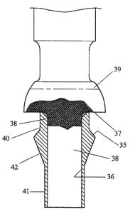
In Figure 3 there is illustrated a guide projection that is produced
as an individual component that can be secured to a valve member adapted for
such a purpose. The guide projection 35 is of a toriodai form having a central
bore 36 extending the length thereof. The bore 36 receives the spigot 38
projecting centrally from the end face 37 of the valve 39 and as shown is
preferably an integral part of the valve.
The guide projection 35 directly abuts the valve and the upper
cylindrical portion 40 functions as a necked area when assembled to the valve.
The tower cylindrical portion 41 is of a thin wall form so that it can be
crimped to
firmly grip the spigot 38 to provide a secure attachment thereto and to the
valve
39. The downwardiy converging portion 42 provides the surface to which the
fuel plume will attach to be guided on a prescribed path as previously
2Q . discussed.
As a modification to the construction shown in Figure 3, the
cylindrical portion 41 could be welded or otherwise secured to the spigot 38
and
when welded the cylindrical portion 41 can be of shorter length or completely
eliminated. A construction wherein the guide projection is not integral with
the
valve is beneficial in maintaining the guide projection at a high temperature
due
to the reduced heat transfer rate from the guide projection. The rate of heat
transfer can be further reduced by increasing the clearance between the guide
projection 35 and the spigot 38 or by providing insulating material
therebetween.
In a further madification, the guide projection can be constructed of
a low heat transfer material particularly a material having a lower heat
transfer
rate than the stainless steel normally used for the valve of a fuel injector
nozzle.
CA 02128426 2003-04-24
8
The lower cylindrical portion 41 can be a separate component from
the guide projection 35 so that the guide projection 35 can have a greater
clearance on the spigot 38 and hence a lower heat transfer rate to the spigot
and to the valve 39. Also the greater clearance enables a limited freedom of
movement of the guide projection that can assist in the shedding of foreign
material deposits on the guide projection. In such construction an independent
component is provided on the spigot below the guide projection that is secured
to the spigot 38 to retain the guide projection correctly located on the
spigot.
In each of the embodiments described the guide projection is co-
axial with the valve member, however, in some application it can be
appropriate
to effect a small degree of deflection of the fuel plume. Accordingly; the
guide
projection can be appropriately inclined to the axis of the valve to provide
the
required deflection of the fuel plume.
It will be appreciated by those skilled in the art that the dimension
of the guide projection are influenced by a number of factors including the
_ dimensions of the injector nozzle the nature of the fluid or fuel and the
velocity of
delivery from the nozzle. .Typical dimension of the projection as shown in
Figure
1 are provided below by way of example only,
Valve Diameter 5.5 mm
Guide Projection Srnall End Diameter 2.5 mm
Guide Projection Included Angle 40°
Guide Projection Length 8.2 mm
The present invention is applicable to poppet type fuel injector
nozzle of all constructions where the fuel issues therefrom in the form of a
plume including injectors where fuel alone is injected and where fuel
entrained
in a gas, such as air, is injected. Examples of specific nozzle constructions
to
which the invention can be applied are disclosed in United States Patent No.
5090625 and International Patent Application WO 91/11609. Also the
injector nozzle as disclosed herein can be used for injecting oth~:
fluid in addition to fuel with similar beneficial control of the fluid plume.