Note: Descriptions are shown in the official language in which they were submitted.
2128695
Lap carrier
The invention relates to a lap carrier for the
reception of yarns, with a rotationally symmetrical body,
the outer face of which forma a surface carrying the
yarn, with a collar projecting axially at one end and
having a thread-reserve groove, and with a receptacle,
located at the other end, for the collar.
Lap carriers of this type have become known from
EP 0,201,826 A2. These lap carriers are provided at each
of their two ends with an annularly extending toothing,
the teeth of which project in the axial direction» The
radially outer faces of the toothings continuously adjoin
the 'surface of the lap carriers which carry the yarn. The
teeth of the toothing located at one end of the lap
carriers are matched respectively to the tooth inter-
spaces of the toothing located at the other end. The
winding of the surfaces carrying the yarn can take place
into the regian of the two toothings and cover a maximum
of 50 % of their total axial extension.
When two lap carriers are placed axially one above the
other, the mutually opposite ~toothings extending
annularly engage in one another in the most favorable
case, the non-wound 50 % of the toothings being respec-
tively guided under the laps of the opposite lap
carriers. The laps located on them therefore lie with
their end faces closely against one another without an
interspace. Tn this way, during transport, the laps can
be prevented from sliding off from the lap carrier and
there is no need to use the otherwise customary
'mS~..~~;,1:'FS.:,'1" 2.~i'.tri~S "i.~...~.t17: T ~..t
.';k, . ', V . -.A.~..'' . rEt'~;:~..,
7,., .. :~ .'.~.T~mi!~"s. .7 1.r. ; ~,a
.fit.., .''K'-.. ..2.~, ., t
..y4. . . ~, , el... .~ . ~~taYt°~
1: nt6 p-..:..
~.:~..::.. , Yt. ...a.. . ar ,. v,.,.. AI . ..
'a.!. w ' ,',~ S ia,.yJ-i n W . ..a1 .. t
't...,v ...t"r.. ...tm.. . ~ 1K. .h ,; ~s '. .
A' ~ s 3,
rr. ... ~',:. , .~~.Y~,m ~ '~ ,'k.<.
'~ ~!'~ -:, ~ t W .. .. ".,.Sb ~ a , , ," : . .
~.~ . ..~,.., . .., n:c.... . ... .. . ;. :y. ~ . .. ~i~' > ,. ".. "'
' '~_2I2~695
' - 2 -
intermediate plates or 'intermediate layers covering the
interspaces. At the same time, storage and transport
space is saved and, in the event of axial compression, it
~is guaranteed that the pressure thereby exerted also
takes effect between the laps, so that the possibility of
relative movements between the laps on the one hand and
the lap carriers on the other hand is virtually excluded.
Far dyeing too. it is important to form a homogeneous
yarn column which consists of lap carriers placed one
above the other and in which the laps located on them lie
with their end faces closely against one another.
To improve guidance between two axially adjacent lap
carriers, there is provided at one end of the lap carrier
a collar which projects axially beyond the toothing and
on which a thread-reserve groove can be accommodated, and
at the other end of the lap carrier a receptacle matched
to the outer dimensions of the collar is provided.
In the known lap carriers, despite the advantages men-
tinned, disadvantages also become noticeable to a marked
extent. During the winding of the lap carriers, first the
thread. reserve provided on the collar offset radially
inwards is wound on. However, in this region, the inside
diameter of the lap carrier is smaller than at the
opposite end, thus leading to problems with the winding
machines which, as regards the other lap carriers of the
state of the art, in so far as these have a thread-
reserve groove, expect this at the end having the larger
diameter. In such a position, however, the thread-reserve
groove cannot be made in a concealed arrangement . When
-,a.,;.. .. :.:,..:;.>
4u.a,...,t.n . . . ...,..... . . ... , .r. - , ~ ~.",:..r-~r..:. .. , - .. ,
2128695
- 3 -
the thread reserve is wound on, the thread has to be
guided onto the yarn-carrying surface located radially on
the outside from the collar, in order to wind this thread
reserve. Since the winding of the yarn-carrying surface
of the known Zap carriers can cover only 50 % of the
axial extension of the toothing, however, this results in
a transitional region which the thread has to bridge by
spanning the exposed 50 % of the toothing. But in any
event, when adjacent lap carriers are placed axially one
above the other and the mutually opposite toothings
engage in one another, this leads to a pinching or
breaking of the thread coming from the thread reserve and
therefore to a reduction in quality, for example as a
result of faulty colorings then occurring, or to
operating faults during unwinding in the event of a
break.
Since it is not possible for the toothing to engage under
the mutually opposite laps without a tilting of the lap
carriers, here too, damage to the thread caused by the
edges of the toothing can occur. Moreover, as a result of
the toothirig, reception reliability is reduced in the
winding apparatus and permanent expansions can occur
there, so that, when the wound lap carriers are inserted
into one another, the expanded teeth can penetrate into
the yarn. So that a tube of this type can be wound, it is
necessary to exchange the receiving plates present on
winding machines for receiving plates of suitable
dimensions, because the known lap carrier has the thread
reserve at the end having the smaller inside diameter,
CA 02128695 2003-07-18
- 4 -
consequerr.tly conversely to what is conventional.
The object on which the invention is based is,
therefore, to design a Iap carrier of the-type described
in the preamble, in such a way that, whilst the known
ad~crantages are preserved, it is possible to place the
waurid lap carriers axially one above the other without
the risk of thread damage or thread jamming.
According to the present invention, there is
provided an axially stackable lap creel for yarn, said lap
creel comprising
a) a rotationally symmetrical body having an outer
surface to support the yarn, said outer surface having an
insertion end and a receiving end;
b) a first collar extending axially from the insertion
end of said outer surface of said body, said collar comprising a
bunching groove on an outer surface of said collar; and
c) a seat located at the receiving end.of said outer
surface, said seat comprising
(i) a shoulder stop arranged radially inwardly of
said outer surface of said body, said outer surface
extending axially beyand said shoulder stop to form an
extension, and
(ii) a second collar located radially inwardly of
said shoulder stop and extending axially at least to
the end of said extension;
wherein said seat is configured such that said first
collar of a first lap creel can be inserted into the seat of a
second, identical lap creel, and the axial dimension.of the first
collar is longer than the axial dimension of the extension, such'
CA 02128695 2003-07-18
_ 5 _
that when a first collar of a first lap creel is inserted into a
seat of a second lap creel, said bunching groove on said first
collar is located radially inwardly of said extension, and a gap
is formed between the insertion end of said outer surface of the
first lap creel and the receiving end of the outer surface of the
second lap~creel.
Preferably, by means of the collars present at both ends of,
the lap carrier, winding onto the surface carrying the yarn
can take place as far as the two ends of this surface. When
two lap carriers according to the invention are placed
with their mutually assigned collars axially one above
the other, the additional collar of one.. lap carrier earn
be inserted into the cylindrical inner face of the other
lap carrier, its collar thereby being introduced simulta-.
neously into the receptacle located radially on the
outside from the additional collar. As a result of this,
the mutually- opposite end faces of adjacent laps lie
directly against one another. There is no need far the
yarn-carrying surfaces which lie against one another to
engage mutually under the laps, and there is therefore no
possibility that the thread will be damaged or jammed. If
these collars are made to project axially, mechanical
damage to the collar, via which unwinding takes place, is
avoided at the same time. The conditions of guidance.are
improved and the thread reserve is protected against
mechanical damage during the insertion of the lap
carriers into, one another: Furthermore, the additional
collar has a smaller inside diameter than the collar
CA 02128695 2003-07-18
- 6 -
possessing the thread-reserve groove, so that, with the
winding machines too, problems no longer arise and
machine conversions can be avoided. Existing receiving
plates an. the winding machines can continue to be used.
Preferably, according to one version of the
invention, provision is made for each lap carrier to have a
stop shoulder for a collar of an axially adjacent,
preferably identical lap carrier. This stop shoulder
determines the depth to which the adjacent lap carrier can
be introduced with its collar into the receptacle. At the
same time, the depth can be set so that a small gap remains
as an interspace between the yarn-carrying surfaces of the
lap carriers, the said surfaces being located with their
ends opposite one another. Since the yarn-carrying surface
of a lap carrier can be wound as far as its two ends, the
thread from the thread reserve accommodated on the collar
can be wound, without transition, onto this face, .so that
~-t is not possible for the thread to be damaged or broken
when the mutually assigned collars to two identical lap
carriers are joined together axially. The interspace
between the axially mutually opposite ends of the yarn
carrying surfaces is dimensioned in such a way that the
thread coming from the thread reserve can be guided
between these without being pinched. However, the inter-
space is of no importance for the direct lying of the end
faces of adjacent laps against one another.
CA 02128695 2003-07-18
d
. _ 7
Preferably, in the lap carriers according to
the invention also, when they are placed axially one
above the other a homogeneous yarn column protected
against slipping off from the lap carriers is formed by
the laps supported with their end faces against one
another, so that there is no need to use intermediate
plates or intermediate layers. In the event of an axial
compression of the lap carriers, it is likevrise
guaranteed that the pressure exerted thereby -also takes
effect between the Zaps.
Preferably, one version of the invention
provides for the yarn-carrying surface to have, in the
region of at least one end, means (8) for the axial
guidance of the thread which can be designed as a groove.
This groove, into which the thread is wound, additionally
prevents the possibility that the lap will slide'off from
the lap carrier beyond the two ends of the yarn-carrying
surface.
Preferably, an additional version of the
invention provides for the outer envelope of the body of
the lap carrier to be shaped sonically at least in
particular regions.
As a result, for example, an even closer packing of the
laps is possible. This allows an even closer packing than
corresponds to the original lap width. Such a lap carrier
is unwound v"i~a the larger outside diameter.
CA 02128695 2003-07-18
g _
Preferably, another embodiment of the invention
provides for the collar and/or additional collar each to be
formed on an insert which respectively has in insert collar
and which is inserted by means of the latter into a
corresponding inner face of a lap carrier. The design can
be made simpler and cheaper thereby.
Preferably, according to one design embodiment,
provision is further made for forming the additional collar
by ribs, the radially outer faces of which form a collar
surface, whilst the ribs can also be oriented radially. The
throughflow can thereby be markedly improved in the overlap
region. The proposed lap carrier can be wound on its entire
circumferential face remaining free and on the thread-
reserve groove.
The invention will now be explained in more
detail by means of the accompanying drawings.
In these:
Figure 1 shows a lap carrier in side view and part
section
Figure ~ shows an alternative con.structioiz .;.v~ewed~
as in Figure 1
Figure 3 shows a side view of a further alterna-
tive construction in part section
Figure 4 shows an enlarged cutout from the joining
region of two lap carriers inserted one
in the. other
Figure 5 shows a lap carrier with an insert in
side view and part section
Figure 6 shows a lap carrier, as in Figure 5, but
with.an insert on both sides
CA 02128695 2003-07-18
a
- 8a -
Figure 7 is a schematic of an alternative collar with
narrow radial ribs.
Figure 8 is a schematic of an alternative collar with
wide radial ribs,
Figure 9A is a schematic of a partial view along
section lines 9A-9A in Figure 7.
Figure 9B is a schematic of a partial view along
section lines 98-9B in Figure 8.
Figure to is a schematic of an alternative collar with
an annular radial inward extension.
Figure 11 is a schematic of an alternative short
collar.
Figure 12 is a schematic of an alternative short collar
with an annular radial inward extension.
Figure 1 shows a diagrammatically represented lap
carrier 1 with an.additional collar 3 located at one end
and offset radially inwards relative to a receptacle 2.
The additional collar 3 is matched in its outer dimen-
lions to the inner dimensiot~.s of a collar 4 and, in the
case of an identical, axially adjacent lap carrier 1, can
thereby~be introduced into .the cylindrical inner face 10
surrounded by the collar 4. A stop houlder ~ for the
bearing of the end face of one end of an identical,
axially adjacent lap carrier 1 can be seen in the
receptacle 2. This makes it possible to determine the
depth to which the collar-4 can be introduced and which
is set so that a small interspace remains between the
ends of the uiutually opposite, yarn-carrying surfaces 7,
CA 02128695 2003-07-18
n
- 8b -
so that the thread, which is guided from the thread
reserve onto the yarn-carrying surface 7, cannot be
pirached. The ot~ier end of the dap carrier 1 shown h,as the
collar 4 with a thread-reserve groove 6. By means of the
thread-reserve groove 6, the thread reserve wound in the
latter is additionally protected during the introduction
of the collar 4 into the receptacle 2. Part of the yarn-
carrying surface 7 can be seen at both ends of the lap
carrier 1.
Figure 2 shows, likewise:represented diagrammati-
cally, a further version of the lap carrier Z, but with
~''...,., "::: ~''' ~ .:, ~ ., "~:
1 r: ~; 'va, , ,
h. It .L.i' .~.~~ ~~~. 'i . Y .. ... A'..,:. , .,.. " -
,~ ...,....,, :.', .. ..' - .~:.' . ,'.: .;: .r .., ~. ;', .,.', . ,. .', '. .
~..... ~.. ~.~ '..,.. ~.~.,....~ ,..
Y. .. . .v\ .,..,.1..v ....... . ,.. . . . . A , .. . '
~" 2128695
_ 9 _
grooves 8 located in the region of the two ends of the
yarn-carrying surface 7. The thread is wound over the
grooves 8, so that it is pressed into the grooves 8, and
consequently the lap is prevented from sliding off from
the lap carrier 1 beyond the ends of the yarn-carrying
surface 7. Moreover, the stop shoulder 5' is shifted
inwards and into the region of the end having the collar
4, the said stop shoulder 5' cooperating with the end
face 26 of the additional collar 3 of an axially adjacent
tube .
Figure 3 too shows a diagrammatic representation
of a lap carrier 1, but with a comically shaped body 9.
A closer packing of the lap carriers 1 is thereby
possible. The diameter of the lap carrier 1 decreases
towards the collar 4, and the yarn-carrying surface 7
merges continuously into the latter, with the result that
the thread coming from the thread reserve can be wound,
without transition, onto the yarn-carrying surface 7.
There is no need to determine an interspace between the
ends of two axially adjacent, yarn-carrying surfaces 7 by
means of the stop shoulder 5 or the thereby determined
depth of introduction of the collar 4, since the ends of
the yarn-carrying surface 7 are not located opposite one
another on one plane. There is therefore no risk of
pinching of the thread coming from the thread reserve. In
this version too, the outside diameter of the additional
collar 3 located at one end and offset radially inwards
relative to the receptacle 2 corresponds to the inside
diameter of the collar 4 located at the other end, so
ryf . ,.
m ...?,
~f > .°, .., n ,
;., ;~n". ..,
M 2128fi9~
- 10 -
that, in the case of an identical, axially adjacent lap
carrier 1, the additional collar 3 can be introduced into
the collar 4, with the result that the end faces of
apposite laps lie directly against one another. Here too,
the collar 4 can be provided with a thread-reserve groove
6.
A section through a part region of two lap
carriers 1 can be seen on an enlarged scale in Figure 4,
showing the collars 3, 4, inserted one in the other, of
two lap carriers 1 located axially one above the other or
next to one another. The collar 4 of one lap carrier 1 is
introduced into the receptacle 2 of the other lap carrier
and is supported with its end on the stop shoulder 5 of
the receptacle 2, with the result that, in the case of
corresponding dimensions. a small interapace can be
produced between the axially mutually opposite ends of
the yarn-carrying surface 7 of the two lap carriers, the
said interspace allowing a pinch-free guidance of the
Lhread from the thread reserve or the thread-reserve
groove 6 onto the yarn-carrying surface 7. This is also
true of the embodiment according to Figure 3, which is
indicated by the dot-and-dash line 7.
In the exemplary embodiment according to
Figure 5, a lap carrier 21 consists of a lap body 15,
which, for example, could also be a cardboard cylinder,
and of an insert 11 which is inserted by means of an
insert collar l4 into the lap body 15. The insert 11 is
therefore removable and, if appropriate, reusable. The
additional collar 3, already described in relation to
> ~,:: . ... . . .
\ . h Y:.
t -.. ~.~, , ...n.:'.. . r.;,. s~
iA ,...a
a ....
...p. 1 ~ ~. '~.>.
a:. '. 1 t
D,d~4 ~r .... s....'~ , .. L : S» ..: :" a
wa.,n,!.. ...... . ... , ?:.''...., . >P.1... ~.$~...~ .>. ,.
..,,p.?,~..,.:!'!~y, an-y ,. . , , ,.
- 11 - _ 2125695
Figure l, and the receptacle 2 having a stop shoulder 5
are foraned on the insert 11. In the exemplary embodiment
according to Figure 5, as a result of the differences in
diameter between the outside diameter of the insert 11
and the outside diameter of the lap body 15, the yarn-
carrying surface 7 has a step which can be avoided by a
variation in the wall thickness of the lap body 15, in
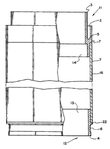
the exemplary embodiment according to Figure 6 the lap
body 16, as shown by the version according to Figure 6.
On account of the smaller diameter of the lap
body 15 according to Figure 5 in relation to the embodi-
went according to Figure 6, it is possible, in an embodi-
went according to Figure 5, to insert the free end of the
lap body 15 into the receptacle 2 of the insert 11, so
that there is no need for a special design of the free
end of the lap body 15 in the embodiment according to
Figure 5. Nevertheless. a thread-reserve groove can be
stamped in there, and a concealed thread reserve can then
also be wound onto the latter.
This is no longer possible in respect of the larger
diameter of the lap body 16 in the embodiment according
to Figure 6, so that, once again. there is provided
there, at the free end of the lap body 16, an insert 12
which can be inserted by means of an insert collar 13
into the lap body 16, in the same way as the insert 11.
At the same time. the insert 12 has a collar 22, by means
of which it bears against the end face of the lap body 16
and the diameter of which corresponds to the outside
diameter of the lap body 16, so that the circumferential
CA 02128695 2003-07-18
- 12 -
face of the collar 22 also becomes a yarn-carrying
surface 7. As already described in respect of the design
according to Figure I, a collar 4 having a thread-reserve
groove 6 then adjoins this collar 22. In the version
according to Figure 6 too, the insert Z2 can be extracted
and, if appropriate, reused. However, the inserts 11 and
12 can also, for example, be adhesively bonded in the
associated lap body 15 and 16 or be produced from
different materials.
Varied designs of the additional collar 3
according to the previous embodiments of Figures 1 to 6 are
represented in Figures 7 to 9A and 9B. Lt ca be seen that
the additional collar 3 does not necessarily have to be
designed in the manner of a closed ring, but on the
contrary can also consist of ribs 17 or 18, as represented
in Figure 8 or Figure 7 respectively. At the same time,
Figure 8 shows ribs 17 having a relatively large radial
extension, whilst Figure 7 shows ribs 18 with relatively
small radial extension. Figures 9A and 9B show a
corresponding end side view which makes this radial
extension clear, also as regards its differences. There,
the left-hand side shows the view 9B-9B according to Figure
8, whilst the right-hand side shows the view 9A-9A
according to Figure 7. The ribs 17 and 18 have a radially
outer face 19 and 20 which forms the outer face of the
"additional collar 3" and which, far example, can be
introduced into the cylindrical inner face 10 of the
embodiment according to Figure 1. It is, of course,
possible also to adopt this design, as shown in Figures 4
CA 02128695 2003-07-18
,a
- 13 -
to 9A and 9B, for the insert 11 according to the embodiment
of Figure 5.
Figures 10 to I2 show varied embodiments of an
insert 11 according to Figure 6 or of the corresponding
end design of an embodiment according to Figure 1. In the
embodiment according to Figure 10, an additional collar
3 has a ring-like skirt 23 which is directed radially in-
wards and which reliably prevents a, for example, partial
deformation of the additional collar 3 and the concentri-
cally arranged orifice 24 of which serves as a.receptacle
for existing receiving plates on winding machines and
also as centering for existing dyeing spears.
The additional collar 3 projecting in the axial
direction has, in addition to the favorable guide length,
the further advantage that, during storage and transport,
the bobbin body can be placed onto the end face of this
additional collar 3, with the result that damage to the
end face of the yarn-carrying surface, with the risk of
a thread break during the unwinding operation, is avoided
in this region. In the embodiments according to Fig-
ores 1l and- 12; this risk is allowed for to.a..qualified
degree. The additional collar 25 used there is shorter
than the additional collar 3 and no longer proj ects or
projects only very slightly beyond the end face of the
yarn-carrying surface 7. Nevertheless, here too, the risk
of damage can be reduced by using the ring-like skirt 23 ,
already described in respect of Figure 10, in the embodi-
went according to Figure 12.
However, in the embodiment according to Figure 11
t . .,:..'~: ,.....:.:- :,.. .:~.:~:. ' .:~..;:._._.: ...;. .. ;.._,.,. ,.. .
. ....'... : ~.~, : '.; ~....~:~ . :~:..~::,. '.: ;': - - .... . .,;. ......
.., :. ,,_. . . .... ...
~ c - - ~ .
Soa .: ~e...,:. '.,~,~,... .n,. :~~;'.,~..... ...: ;.. ~~~~~ ~'..:,~..w
~~..,;.,:..'..;. ~,. ~. ~,~~:~. .....:
~~, (~ ~.'.."t:.i" .,....... . ~'.... .;: ~. , . ':.;:,~ ...,;' :...;... . .
..::'~ . . .::: ~,-:'..'. . . ~.: ' ::.~- ... ..:,. .,-.. :..~.. .; .;. ...~
,... ..- ~,' ; '.
~(p~'~'~ 1':1 ;..a ._. y . w
T,. S1. 1.'.~'...~........ . :_t...t., , ,.. .. ,~5y~- ....... . ,. . . . . .
.... . . ..
~1~~695
- 14 -
too, the standing toed is distributed to two end. sides,
so that, here too, the risk o~ damage is reduced.
......... . ;~ ~:;r .ø~ . . . . :~1~ .., .. . .
2128695
- 15 _ _
List of reference symbols used
1 Lap carrier
2 Receptacle
3 Additional collar
4 Collar
5, 5' Stop shoulder
6 Thread-reserve groove
7 Yarn-carrying surface
8 Means fox thread guidance
9 Body
Inner face
11 Insert
12 Insert
13 Insert collar
14 Insert collar
Lap body
16 Lap body
17 Ribs
18 Ribs
19 Radial outer faces
Radial outer faces
21 Lap carrier
22 Collar
23 Ring-like skirt
24 Orifice
Additional collar
26 End face