Language selection

Search

Patent 2128721 Summary

Third-party information liability

Some of the information on this Web page has been provided by external sources. The Government of Canada is not responsible for the accuracy, reliability or currency of the information supplied by external sources. Users wishing to rely upon this information should consult directly with the source of the information. Content provided by external sources is not subject to official languages, privacy and accessibility requirements.

Claims and Abstract availability

Any discrepancies in the text and image of the Claims and Abstract are due to differing posting times. Text of the Claims and Abstract are posted:

  • At the time the application is open to public inspection;
  • At the time of issue of the patent (grant).
(12) Patent Application: (11) CA 2128721
(54) English Title: WARNING SYSTEM DISTINGUISHING WHEEL SKIDDING AND WHEEL SLIPPING
(54) French Title: SYSTEME D'AVERTISSEMENT DE DERAPAGE OU DE PATINAGE
Status: Dead
Bibliographic Data
(51) International Patent Classification (IPC):
  • G01M 17/06 (2006.01)
  • B60Q 9/00 (2006.01)
  • B60R 16/02 (2006.01)
(72) Inventors :
  • MAY, KENNETH A. (United States of America)
  • OSTERTAG, STEVEN E. (United States of America)
(73) Owners :
  • ZEXEL TORSEN INC. (United States of America)
(71) Applicants :
(74) Agent: KIRBY EADES GALE BAKER
(74) Associate agent:
(45) Issued:
(86) PCT Filing Date: 1992-12-07
(87) Open to Public Inspection: 1993-08-05
Availability of licence: N/A
(25) Language of filing: English

Patent Cooperation Treaty (PCT): Yes
(86) PCT Filing Number: PCT/US1992/010513
(87) International Publication Number: WO1993/014962
(85) National Entry: 1994-07-22

(30) Application Priority Data:
Application No. Country/Territory Date
824,039 United States of America 1992-01-23

Abstracts

English Abstract


A warning system alerts a driver of a motor vehicle to different types of
traction losses. A first sensing circuit (10) detects a
loss of wheel adhesion by monitoring a vehicle drive line for a pronounced
vibration within a range of between ten and fifteen
Hertz. A second sensing circuit (12) monitors a brake light circuit to detect
application of a vehicle brake. A logic circuit (28)
combines outputs (A and B) from the first and second sensing circuits and
outputs command signals (C and D) that distinguish
between a loss of wheel adhesion due to wheel skidding and a loss of wheel
adhesion due to wheel slipping. A warning device
includes two indicators (36 and 38) that receive the respective command
signals and produce sensorially distinguishable warning
signals for eliciting different responses from the driver.


Claims

Note: Claims are shown in the official language in which they were submitted.

WO 93/14962 PCT/US92/10513
- 8 -
WE CLAIM:
1. A warning system for alerting a vehicle driver to
different types of traction losses comprising:
a first sensing circuit for detecting a loss of adhesion
by a vehicle wheel with respect to a relatively moving
traction surface;
a second sensing circuit for detecting application of a
vehicle brake;
a logic circuit for combining sensor signals from said
first and second sensing circuits and for producing a first
command signal indicative of the detection of both the loss
of adhesion by said vehicle wheel and the application of said
vehicle brake and a second command signal indicative of the
detection of the loss of adhesion by said vehicle wheel but
not the application of said vehicle brake;
a first indicator responsive to the first command signal
of said logic circuit for alerting the vehicle driver to
wheel skidding; and
a second indicator responsive to the second command
signal of said logic circuit for alerting the vehicle driver
to wheel slipping.
2. The warning system of claim 1 in which said first
and second indicators produce respective warning signals that
are sensorially distinguishable for eliciting different
responses from the vehicle driver.
3. The warning system of claim 2 in which said
respective warning signals are sensorially distinguishable by
the driver without changing a driver's line of sight away
from the relatively moving traction surface.
4. The warning system of claim 3 in which said
respective warning signals are audible.
WO 93/14962 PCT/US92/10513
- 9 -
5. The warning system of claim 4 in which one of said
warning signals produced by the first indicator is a sound
suggestive of a skidding wheel.
6. The warning system of claim 5 in which one of said
warning signals produced by the second indicator is a sound
suggestive of a slipping wheel.
7. The warning system of claim 1 in which said first
sensing circuit includes a sensor for detecting a pronounced
vibration induced by said vehicle wheel having lost adhesion
with respect to the relatively moving traction surface.
8. The warning system of claim 7 in which the
pronounced vibration detected by said sensor is induced by
both wheel skidding and wheel slipping.
9. The warning system of claim 8 in which said first
sensing circuit includes a filter for isolating a range of
frequencies of the pronounced vibration.
10. The warning system of claim 9 in which said first
sensing circuit also includes a level detector for measuring
an amplitude of the isolated frequency range and a comparator
for comparing the amplitude of the isolated frequency range
with a threshold to detect a loss of adhesion by said vehicle
wheel.
11. A system for warning a vehicle driver of both wheel
skidding and wheel slipping comprising:
a first sensing circuit for detecting a pronounced
vibration induced by a vehicle wheel having lost adhesion
with respect to a relatively moving traction surface;
a second sensing circuit for detecting application of a
vehicle brake;
a logic circuit combining outputs of said first and
second sensing circuits for distinguishing between a loss of
WO 93/14962 PCT/US92/10513
- 10 -
wheel adhesion due to wheel skidding and a loss of wheel
adhesion due to wheel slipping; and
a warning device for producing sensorially
distinguishable warning signals for eliciting different
responses from the vehicle driver in response to the
detection of wheel skidding and wheel slipping.
12. The system of claim 11 in which said first sensing
circuit includes a sensor for monitoring a vehicle drive line
for the pronounced vibration.
13. The system of claim 12 in which said first sensing
circuit includes a filter for isolating a range of
frequencies of the pronounced vibration.
14. The system of claim 13 in which said first sensing
circuit includes a level detector for measuring an amplitude
of the isolated frequency range and a comparator for
comparing the amplitude of the isolated frequency range with
a threshold to detect the loss of adhesion by said vehicle
wheel.
15. The system of claim 11 in which said warning
signals are sensorially distinguishable by the driver without
changing a driver's line of sight away from the relatively
moving traction surface.
16. The system of claim 15 in which said warning
signals are audible.
17. The system of claim 16 in which one of said warning
signals is a sound suggestive of a skidding wheel and the
other of said warning signals is a sound suggestive of a
slipping wheel.
18. The system of claim 11 in which wheel skidding is
distinguished by the detection of both the loss of adhesion
by a vehicle wheel and the application of a vehicle brake and
wheel slipping is distinguished by the detection of the loss
WO 93/14962 PCT/US92/10513
- 11 -
of adhesion by a vehicle wheel but not the application of a
vehicle brake.
19. A method of alerting a vehicle driver to different
types of traction losses comprising the steps of:
sensing vehicle operating conditions with a first
sensing circuit for detecting a loss of adhesion by a vehicle
wheel with respect to a relatively moving traction surface;
sensing vehicle operating conditions with a second
sensing circuit for detecting application of a vehicle brake;
combining outputs of said first and second sensing
circuits in a logic circuit for distinguishing between a loss
of wheel adhesion due to wheel skidding and a loss of wheel
adhesion due to wheel slipping; and
producing sensorially distinguishable warning signals
for eliciting different responses from the vehicle driver to
the detection of wheel skidding and wheel slipping.
20. The method of claim 19 in which said step of
combining outputs includes distinguishing wheel skidding by
the detection of both the loss of adhesion by said vehicle
wheel and the application of said vehicle brake and
distinguishing wheel slipping by the detection of the loss of
adhesion by said vehicle wheel but not the application of
said vehicle brake.
21. The method of claim 20 in which said step of
producing warning signals includes producing warning signals
that are sensorially distinguishable by the driver without
changing a driver's line of sight away from the relatively
moving traction surface.
22. The method of claim 21 in which said step of
producing warning signals includes producing warning signals
that are suggestive of wheel skidding and wheel slipping.
23. The method of claim 22 in which said step of
producing warning signals includes producing one of the
warning signals as a sound suggestive of a skidding wheel and
WO 93/14962 PCT/US92/10513
- 12 -
the other of the warning signals as a sound suggestive of a
slipping wheel.
24. The method of claim 19 in which said step of
sensing vehicle operating conditions with said first sensing
circuit includes monitoring a vehicle drive line for the
pronounced vibration.
25. The method of claim 24 in which said step of
sensing vehicle operating conditions with said first sensing
circuit includes isolating a range of frequencies of the
pronounced vibration.
26. The method of claim 25 in which said step of
sensing vehicle operating conditions with said first sensing
circuit includes measuring an amplitude of the isolated
frequency range and comparing the amplitude of the isolated
frequency range with a threshold to detect the loss of
adhesion by a vehicle wheel.
27. The method of claim 20 in which said step of
sensing vehicle operating conditions with said second sensing
circuit includes monitoring a vehicle brake light circuit.

Description

Note: Descriptions are shown in the official language in which they were submitted.

~--~093/14962 212 8 7 2 1 PCT/US92/10513
-- 1 --
TITLE
WARNING SYSTEM DIST~NGVIS~IING
WHEEL SKIDDING AND WHEEL SUPPING
TECHN~CAL FIELD
The invention relates to the field of vehicle
traction systems and, in particular, to such systems that
respond to the detection of a loss of traction with.a driver
warning signal.
:
BACKGROUND
Most traction control systems are designed to~limit
either wheel skidding or wheel slipping. The systPms that
limit wheel skidding help t~ decelerate vehicles by
preventing wheels from rotating slower than required for
maintaining adhesion with a traction surface, and the systems
that limit wheel slipping help to accelera~e vehicles by
preventing drive wheels from rotating faster than required
for maintaining the same adhesion. However, some more
complicated traction systems are designed to limit both wheel
skidding and wheel slipping.
Such trastion control technology has been available
for many years~ and the advantages of this technology are
widely known. Nevertheless, most automobiles are
manufactured without electronic traction control systems for
limiting either wheel skidding or wheel slipping, and a much
smaller percentage of automo~iles are manufactured to limit
both. One reason for this may be the high cost of
manufacturing traction control systems to operate with a
degree of reliability required to supersede driver control
over a vehicle. For instance, systems for limiting wheel
skidding periodically take control over vehicle brakes.
~ h l
WO93/14962 PCT/US92/10513
Systems for limiting wheel slipping periodically take control
over either engine output power or its distribution to the
drive wheels.
Although drivers may not be capable of responding
as rapidly or effectively as advanced traction control
systems to changes in vehicle operating conditions, at least
some improvement to driving performance may be possible by
alerting drivers to the detection of an impending loss of
traction. This information about an impending loss of
traction is available from traction control technology at a
small fraction of the cost of a complete traction control
system, because the driver retains responsibility for taking
remedial action.
SUMMARY OF INV~NTMN
The invention involves a warning system for
alertin~ a driver about two different types of traction
losses, nam~ly, wheel ~kidding and wheel slipping. Once
either of the two types of traction losses are detected, a
warning device emits one of two sensorially distinguishable
signals for eliciting different responses from the driver to
the detection of wheel skidding or wheel slipping.
The correct driver response to the detection of
wheel skidding is to at lea6t partially release the vehicle
brakes, whereas the correct response to the detection of
wheel slipping is to at least partially release the vehicle
throttle. The two signals emitted by the warning device are
made distinguishable so that the driver can learn to make
correct responses within a minimum of reaction time to avoid
a more serious loss of traction that could involve a loss of
control over the vehicle.
Preferably, the two warning signals are
distinguishable by the driver without changing the driver's
2 1 2 ~ ~ 2 1
~0 93/14!962 . P~/US92/10513
- 3
line of sight away from the traction surface over which the
vehicle is being driven. For example, the signals can be
presented in a holographic display or the signals can be
composed of sound including speech. To further help elicit
the correct response from the driver, one of the sounds can
be suggestive of wheel skidding such as a screeching sound,
and the other sound can be suggestive of wheel slipping such
as a whining sound. However, neither sound should be
especially alarming to discourage the driver from making an
inappropriate response.
A first sensing circuit monitors the vehicle drive
train for a pronounced vibration that is known to accompany a
loss of adhesion by a vehicle wheel with respect to a
relatively moving traction surface. The pronounced
vibration, which is generally within a range of between ten
-~ and fifteen hortz, accompaniesi both wheel skidding and wheel
slipping. A second sensing circuit preferably monitors a
brake light circuit to detect application of the vehicle
brakes. A logic circuit combines outputs from both sensing
circuits to distinguish between a loss of adhesion due to
wheel skidding and a loss of adhesion due to wheel slipping.
., ~
The logic circuit outputs a first command signal
indicative of wheel skidding in response to the detection of
both the loss of wheel adhesion and the application of the
brakes. A second command ~ignal indicative of wheel slipping'~
is output from the logic circuit in response to the detection
of the loss of wheel adhesion but not the application of the
brakes. The two command signals control a warning device for
producing the sensorially distinguishable signals that are
intended to help elicit different correct responses from the
driver.
wo 93/l4~ 2 8 7 2 1 PCT/USY2/10513 t~
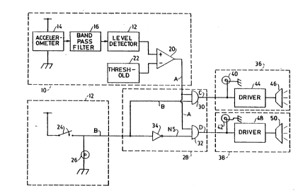
DRAWINGS
FIG. l is a schematic diagram of an electronic
circuit proposed for a new driver warning system
distinguishing wheel skidding and wheel slipping.
.. . .
FIG. 2 is a schematic diagram of an all wheel drive
vehicle incorporating the new warning system.
DE~AILED DESCRIPTION
The new warning syste~ has two sensing circuits lO
and 12 shown in FIG. l. The sensing circuit lO includes an
accelerometer 14 or other known sensor (e.g. rotational speed
sensor) for measuring vibration in a vehicle drive line. A
band pass filter 16 receives output from the accelerometer 14
and transmits a limited band of frequencies between ten to
fifteen hertz - the known frequency range of rotational speed
fluctuations induced by a vehicle wheel having lost adhesion
with respect to a relatively moving traction surface.
A level detector 18 monitors the amplitude of the
limited band of frequencies and outputs a root-mean-square
value to one input of a comparator 20. The other input of
comparator 20 is supplied by a threshold setting 22, which is
a minimum root-mean-square value of the frequency band
characteristic of a loss of adhesion by one of the vehicle
wheeis. Output of the comparator 20 is a logical binary
signal ~A~t having "high" and "low" states that respectively
distinguish between root-mean-square values above and below
the threshold setting.
The sensing circuit 12 is associated with a vehicle
brake light circuit including a brake switch 24 that is
closed in response to application of the brakes (e.g.,
depression of brake pedal) and a brake light 26. The closed
and open positions of the brake switch 24 produce a logical
-~093r14962 2 12 ~ 7 2 i PCT/US92/10~13
binary signal "B" also having "high" and "low" states that
respectively di~tinguish between the brakes being applied and
not applied.
The two logical binary signals "A" and "B" are
combined in a logic circuit 28 that includes two logical
"AND" gates 30 and 32. The signal "A" provides one of the
inputs to each of the "AND" gates 28 and 30. The signal "B"
provides the other input to "AND" gate 30, but an inverter
(or "NOT" gate) 34 inverts the signal "B" to a logicaI binary
signal "NB", which has the logical value "NOT B" and provides
the other input to "AND" gate 32. Output of the "AND" gate
30 is a logical binary signal "C" that has a "high" state
only if both of the signals "A" and "B" also have high
states. Similarly, "AND" gate 32 outputs a logical binary
signal "D" that has a "high" state only if both signals "A"
and "NB" also have "high" states.
~ . .
A "high" state of signal "C" represents a situation
in which both a loss of wheel adhesion has been detected and
the vehicle brakes have been applied. This indicates that
the loss of traction is-due to wheel skidding, where at least
one of the wheels is held from rotating as much as required
to maintain adhesion with a relatively movinq traction
surface. A "high" state of signal "D" represents a situation
where a loss of traction has occurred without the brakes
being applied. This indicates that the loss of traction is '~
due to wheel slipping, where at least one of the wheels is
driven to rotate more than required to maintain adhesion with
a relatively moving traction surface. Lateral wheel slipping
in which the wheels are moved out of their plane of rotation
by lateral acceleration of the vehicle over the traction
surface also satisfies the conditions for a "high" state of
signal "D". Nonetheless, the correct response to either form
of wheel slipping is to diminish throttle and allow the
slipping wheel to regain traction.
212'8721 .-
WO93/14962 PCT/US92/10513
The "high" states of signals "C" and "D" exit thelogic circuit 28 as system voltages capable of powering a
warning devic~ that includes both a wheel skidding indicator
36 and a wheel slipping indicator 38. Both indicators 36 and
38 include respective warning lamps 40 and 42 that are
intended to illuminate separate warning messages on a driver
display panel. The indicator 36 also includes a driver 44
and a speaker 46 for emitting a sound suggestive of wheel
skidding, such as a screeching sound. Similarly, a driver 48
and a speaker 50 of the indicator 38 produce a sound
suggestive of wheel slipping, such as a whining sound. Of
course, a single speaker or piezo transducer could be driven
to emit the different~sounds.
- ~ .
Although the respective warning sounds are intended
to be suggestîve of wheel skidding and wheel slipping,
neither sound is intended to ~e overly alarming; and both
sounds are intended to be easily distinguishable from the
actual sounds of wheel skidding and wheel slipping. For
example, the screeching sound is prefera~ly softened to
dampen any shrill tones that could induce excessive alarm in
the driver. The warning sounds are made distinguishable from
the actual sounds they suggest so that information about
vehicle performance from the actual sounds can also be
discerned by the driver.
A preferred installation of the warning system in
an all wheel drive vehicle is shown in FIG. 2. The vehicle
has two front wheels 52 and 54 and two rear wheels 56 and 58,
all of which are driven by a vehicle drive train that
includes three differentials 60, 62, and 64~ The front
differential 60 interconnects axle halves of the two front
wheels 52 and 54 with a front drive shaft 66. The rear
differential 62 similarly interconnects axle halves of the
two rear wheels 56 and 58 to a rear drive shaft 68. The two
drive shafts 66 and 68 are interconnected with each other and
with a source of motive power (not shown) by center
~ differential 64.
::
~'-~093/14962 2 i 2 ~ 7 2 1 PCT/US9~/10513
- 7
An accelerometer 70, incorporated as a part of a
vibration sensing circuit, is attached to the center
differential 64 to detect mechanical vibrations within a
frequency band between ten and fifteen hertz in the drive
line to all four wheels. A brake ligh~ switch 72 is
similarly incorporated into a brake application sensing
circuit. Respective sensor signals 74 and 76 originating
from the accelerometer 70 and brake light switch 72 are input
to a logic circuit 78 that distinguishes wheel skidding and
wheel slipping. A command signal 80 is conveyed from the
logic circuit 78 to a warning device 82 that is mounted in a
vehicle dash board 84. The warning device 82 emits two
sensorially distinguishable signals in response to the
command signal 80 for separately alerting à driver to the
detection of wheel skidding and wheel slipping.
The warning system is preferably made as simple and
as inexpensive as ~ossible to provide a low cost alternative
to more expensive traction control systems. However, more
than one sensor may be needed to detect a loss of adhesion by
wbeels that are not connected to a common drive line.
Additional sensors can also be used to provide information to
the driver about which wheel has experienced a loss of
adhesion.
The sensor, logic, and warning device circuits can
~e constructed from discrete components or can be
incorporated into a microprocessor system. Sensing or
processing capabilities already available in vehicles can
also be used in place of one or more components of the
warning system.

Representative Drawing
A single figure which represents the drawing illustrating the invention.
Administrative Status

For a clearer understanding of the status of the application/patent presented on this page, the site Disclaimer , as well as the definitions for Patent , Administrative Status , Maintenance Fee  and Payment History  should be consulted.

Administrative Status

Title Date
Forecasted Issue Date Unavailable
(86) PCT Filing Date 1992-12-07
(87) PCT Publication Date 1993-08-05
(85) National Entry 1994-07-22
Dead Application 1996-06-09

Abandonment History

There is no abandonment history.

Payment History

Fee Type Anniversary Year Due Date Amount Paid Paid Date
Application Fee $0.00 1994-07-22
Maintenance Fee - Application - New Act 2 1994-12-07 $100.00 1994-12-02
Registration of a document - section 124 $0.00 1995-02-03
Owners on Record

Note: Records showing the ownership history in alphabetical order.

Current Owners on Record
ZEXEL TORSEN INC.
Past Owners on Record
MAY, KENNETH A.
OSTERTAG, STEVEN E.
ZEXEL-GLESSON USA INC.
Past Owners that do not appear in the "Owners on Record" listing will appear in other documentation within the application.
Documents

To view selected files, please enter reCAPTCHA code :


To view images, click a link in the Document Description column. To download the documents, select one or more checkboxes in the first column and then click the "Download Selected in PDF format (Zip Archive)" or the "Download Selected as Single PDF" button.

List of published and non-published patent-specific documents on the CPD .

If you have any difficulty accessing content, you can call the Client Service Centre at 1-866-997-1936 or send them an e-mail at CIPO Client Service Centre.


Document
Description 
Date
(yyyy-mm-dd) 
Number of pages   Size of Image (KB) 
Description 1993-08-05 7 382
Drawings 1993-08-05 2 40
Claims 1993-08-05 5 229
Cover Page 1993-08-05 1 20
Representative Drawing 1998-07-27 1 11
International Preliminary Examination Report 1994-07-22 12 360
Fees 1994-12-02 1 62