Language selection

Search

Patent 2128768 Summary

Third-party information liability

Some of the information on this Web page has been provided by external sources. The Government of Canada is not responsible for the accuracy, reliability or currency of the information supplied by external sources. Users wishing to rely upon this information should consult directly with the source of the information. Content provided by external sources is not subject to official languages, privacy and accessibility requirements.

Claims and Abstract availability

Any discrepancies in the text and image of the Claims and Abstract are due to differing posting times. Text of the Claims and Abstract are posted:

  • At the time the application is open to public inspection;
  • At the time of issue of the patent (grant).
(12) Patent: (11) CA 2128768
(54) English Title: AGITATOR WITH ENHANCED CLOTHES ENGAGING VANE FOR AUTOMATIC WASHER
(54) French Title: AGITATEUR DE LESSIVEUSE AUTOMATIQUE A AILETTE AMELIOREE D'ENTRAINEMENT DES VETEMENTS
Status: Expired
Bibliographic Data
(51) International Patent Classification (IPC):
  • D06F 13/02 (2006.01)
(72) Inventors :
  • PINKOWSKI, ROBERT J. (United States of America)
(73) Owners :
  • WHIRLPOOL CORPORATION (United States of America)
(71) Applicants :
  • WHIRLPOOL CORPORATION (United States of America)
(74) Agent: KIRBY EADES GALE BAKER
(74) Associate agent:
(45) Issued: 2006-04-25
(22) Filed Date: 1994-07-25
(41) Open to Public Inspection: 1995-03-01
Examination requested: 2001-04-26
Availability of licence: N/A
(25) Language of filing: English

Patent Cooperation Treaty (PCT): No

(30) Application Priority Data:
Application No. Country/Territory Date
08/114,663 United States of America 1993-08-31

Abstracts

English Abstract

An improved agitator construction is provided for an automatic clothes washing machine in which a surface or contour of a vane carried on a portion of the agitator which is intermittently rotated in a single direction is shaped to enhance engagement between the vane and the items being washed and to retard the items from moving at least one of radially and upwardly relative to the agitator. The vane, which may be a helical vane, may be provided with a lower surface angled downwardly and outwardly in a radial direction, or may be provided with one or more steps having a relatively steep sloped wall facing in a direction leading away from the direction of rotation of the agitator and a relatively shallow sloped wall facing in a direction leading toward the direction of rotation of the agitator, or both shapes.


French Abstract

Construction d'agitateur améliorée pour une machine à laver le linge automatique dans laquelle une surface ou un contour d'une aube portée sur une portion de l'agitateur qui est mise en rotation de manière intermittente dans un seul sens est formée pour renforcer la prise entre l'aube et les articles lavés et pour retarder le déplacement des articles dans au moins l'une des directions radiales et vers le haut par rapport à l'agitateur. L'aube, qui peut être une aube hélicoïdale, peut être prévue avec une surface inférieure coudée vers le bas et vers l'extérieur dans une direction radiale, ou peut être prévue avec un ou plusieurs crans ayant une paroi relativement inclinée tournée dans une direction en éloignement du sens de rotation de l'agitateur et une paroi relativement peu inclinée tournée dans une direction vers le sens de rotation de l'agitateur, ou ayant les deux formes.

Claims

Note: Claims are shown in the official language in which they were submitted.


CLAIMS

1. In an automatic washer having a washing receptacle
for containing washing liquid and items to be washed,
agitator means within said receptacle for imparting a
rollover motion to said items to be washed, and drive means
for driving said agitator means, said agitator means
comprising:
a lower agitator element driven by the drive means
in an oscillatory manner; and
an upper agitator element mounted above said lower
agitator element and co-axial therewith, said upper
agitator element being positively rotationally driven
by said drive means in one direction only, and a
helical vane rigidly affixed to and extending outwardly
from a perimeter of said upper agitator element, with a
surface configuration of said vane shaped to enhance
engagement between said items and said vane, said vane
having a smooth and continuous lower surface angled
downwardly and outwardly in a radial direction from
said upper agitator element such that rotation of said
helical vane with said upper agitator element forces
said items to be washed in a downward direction along
said upper agitator element and retards radial outward
movement of said items away from said agitator element.

9


2. In an automatic washer as claimed in claim 1,
wherein a lower end of said upper agitator element is
received in overlapping relationship with respect to an
upper end of said lower agitator element.

3. An agitator assembly for an automatic clothes
washing machine comprising:
a lower agitator element;
an upper agitator element positioned above said
lower agitator element;
drive means for driving said lower agitator
element in an oscillatory manner and said upper
agitator element in a unidirectional manner; and
a helical vane located on an outer portion of said
upper agitator element, being shaped to retard said items
from moving radially outwardly along an underside of said
helical vane, in that said vane has a smooth and continuous
lower surface angled downwardly and outwardly in a radial
direction from said upper agitator element for urging
articles adjacent thereto in a downward direction and
retarding radial outward movement of said articles away from
said agitator element.

4. An agitator assembly for an automatic washing
machine as claimed in claim 3, wherein said lower agitator
element includes a lower skirt portion having a plurality of

10


generally vertically disposed vanes extending upwardly and
radially outwardly therefrom.

5. In a clothes washing machine having a washing
receptacle, means for effecting a rollover movement of the
clothes in the receptacle during a washing operation, said
means comprising:
a double-action agitation means mounted
substantially vertically including
an oscillating lower element provided with vanes
to direct clothes outwardly toward a perimeter of said
receptacle; and
a unidirectional intermittently rotating upper
element having a helical vane for positively urging
clothes downwardly to said lower element, said vane
having a contour shaped to enhance engagement between
said clothes and said vane, said vane having a smooth
and continuous lower contour angled downwardly and
outwardly in a radial direction along said upper
agitator element and such that rotation of said helical
vane with said upper agitator element forces said
clothes in a downward direction along said upper
agitator element and retards radial outward movement of
said clothes away from said agitator element;
said upper and lower elements interacting to
produce said rollover movement of said clothes during
the washing operation.

11


6. In a clothes washing machine having a washing
receptacle claimed in claim 5, wherein said vane means
associated with the upper element comprises a helical vane
rigidly affixed to and extending outwardly from a perimeter
of said upper agitator element.

7. In a clothes washing machine as claimed in
claim 5, wherein lower end of said upper agitator element is
received in overlapping relationship with respect to an
upper end of said lower agitator element.

8. In a clothes washing machine as claimed in
claim 5, wherein said lower agitator element includes a
lower skirt portion having a plurality of generally
vertically disposed vanes extending upwardly and radially
outwardly therefrom.

9. A vertical axis agitator comprising:
a vertical axis tubular barrel portion;
said upper portion having a vane extending
radially outward from said barrel portion and
extending in a helical direction around said
barrel portion;
said vane having an attachment to said barrel
portion at a root end thereof and a free distal
tip radially spaced from said barrel portion;

12


said vane having a lower surface which is
smooth in said helical direction; and
said distal tip being spaced vertically below
said root end as measured along a line
perpendicular to said barrel portion.

10. In an automatic washer having a washing receptacle
for containing washing liquid and items to be washed, an
agitator within said receptacle for imparting a rollover
motion to said items to be washed, and drive means including
a drive shaft for driving said agitator in an oscillatory
manner, said agitator comprising:
a lower portion mechanically coupled to said drive
shaft for oscillatory movement;
an upper portion with a vertical axis tubular
barrel portion;
a one-way clutch mechanism mechanically coupled
between said drive shaft and said upper portion to
drive said upper portion in intermittent rotary motion;
said upper portion having a vane extending
radially outward from said barrel portion and
extending in a helical direction around said
barrel portion;
said vane having an attachment to said barrel
portion at a root end thereof and a free distal
tip radially spaced from said barrel portion;


13


said vane having a lower surface which is
smooth in said helical direction; and
said distal tip being spaced vertically below
said root end as measured along a line
perpendicular to said barrel portion.


14

Description

Note: Descriptions are shown in the official language in which they were submitted.


~ CA 02128768 2004-11-09
I _0 N_
T I T L E
"AGITATOR WITH ENHANCED
CLOTHES ENGAGING VANE FOR AUTOMATIC WASHER"
HACRGROUND OF THE INVEN!~ION
This invention relates to an agitator for a vertical axis
automatic washing machine in which the agitator oscillates to
provide a tumbling or rollover motion to the clothes or other
articles contained within the machine.
l0 Many types and constructions of agitators are well known in
the art including a combined oscillating and unidirectional
agitator such as that disclosed in U.S. Patent No. 3,987,651,
assigned to the assignee of the present application.
That patent discloses an agitator having a lower agitator
element driven in an oscillatory manner and an upper agitator
element mounted coaxially with the lower agitator element and
driven rotationally in one direction only. Means, such as a
helical vane, are provided with the upper agitator element for
imparting a downward motion to the items to be washed. The
2o helical vane presents a continuous ramp surface facing the
direction of rotation such that clothing items which strike the
vane will be continuously urged downwardly toward the lower
agitator element. The patent also discloses that a plurality of
such helical vanes may be provided on the upper agitator element.
SUMMARY OF THE INVENTION
The present invention provides an improved agitator
construction which combines a lower oscillating agitator element
with a unidirectional rotating upper agitator element. Means,
which again may be in the form of a helical vane, are provided on
1


PA-7132-O-Aw-USA
the upper agitator element to engage the clothes or other items
to be washed as the upper agitator element rotates. The vanes of
the upper agitator element, however, are shaped in such a manner
so as to retard the items from moving away from the vans as it
rotates or relative to the vane in an upwardly manner. Thus, the
vane can have a contour, preferabl;l on its lower surface, which
is shaped to enhance engagement between the items and the vane.
In this manner, the items are caused to move downwardly along the
agitator as the agitator is rotationally driven.
In a first embodiment of the invention, the vane is
illustrated in the form a helical vane in which the lower surface
of the vane extends downwardly and outwardly in a radial
direction from the agitator. In this manner the vane has an
undercut appearance which helps to retard the items from moving
radially outwardly with respect to the vane as the agitator
rotates. That is, the items are prevented from sliding radially
outwardly off of the vane since the vane is tipped downwardly
from horizontal. As the agitator rotates the downward spiral of
the vane urges the items downwardly and since the items remain .
"capture" or engaged by the vane, they move downwardly rapidly.
In a second embodiment of the invention a helical vane is
again illustrated in which a lower surface of the vane is
provided with a plurality of wedge shaped steps. The steps have
a substantially vertical wall on a side leading away from the
direction of rotation and a ramp wall on a side leading toward
the direction of rotation. Thus, as the upper agitator element
is rotated, the ramp walls will permit the items to be urged
downwardly by the vane and when the rotation of the agitator
stops, the short vertical wedge walls will engage the items and
retard them from moving upwardly along an underside of the
2


~~~8"~~0
PA-1132-0-AW-USA
helical vane. In this manner, tree items will be caused to move
downwardly along the agitator more quickly.
BRIEF DESCRIPTION OF THE DRAWINGS
FIG. 1 is a view, partially broken away, of a conventional
automatic washing machine assembly provided with an improved
agitator means according to the present invention.
' FIG. 2 is a vertical cross sectional view of the improved
agitator means of the present invention.
FIG. 3 is a side elevational view of an upper portion of the
agitator means of FIG. 1.
FIG. 4 is a top view of the upper portion of FIG. 3 with a
top cap removed.
FIG. 5 is a side cross sectional view of the upper portion
of FIG. 3.
FIG. 6 is a bottom elevational view of the upper portion of
FIG. 3.
FIG. 7 is a side elevational view of a second embodiment of
an upper portion of an agitator means according to the present
invention.
FIG. 8 is a side elevational view of the upper portion of
FIG. 1, rotated 90° about a vertical axis.
FIG. 9 is a top view of the upper portion of FIG. 7.
FIG. 10 is a bottom elevational view of the upper portion of
FIG. 7.
FIG 11 is a side sectional view taken generally along line
XI-XI of FIG. 8.
DETAINED DESCRIPTION OF THE PREFERRED EMBODIMENTS
In FIG. 1, an automatic washing machine is shown generally
at ZO including a frame 11 carrying vertical panels 12 forming
the sides, front and back of the machine. A hinged lid 13 is
3


'~r,..
PA-7132-n-AW-USA
provided,in the usual manner to provide access to the interior of
the washing machine. The washing machine 10 has the usual
console 14 including a timer dial 1.5 and a program selector 16.
Electronic controls can be utilized as known in the art.
Internally of the machine there is situated an imperforate
tub 17 which is supported within the cabinet by means of a
support member 18. A perforate washing receptacle or basket 22
is positioned concentrically within the tub 17. Centrally of the
perforate washing basket 22 is an improved agitator means which
has been designated generally in the drawings at reference
numeral 23. As is known, liquid may be introduced into the
washing machine by means of a solenoid controlled inlet valve
which directs the liquid through a conduit and through an anti-
syphon device into the washing area.
A motor 30 operates through a transmission. A clutch and
brake assembly is provided for energizing the agitator means 23
during washing, and for disengaging the agitator and engaging a
spin tube for spinning the basket 22 during the liquid extraction
portion of the washing phase. All of the drive elements and
hydraulic units described thus far are conventional and vertical
axis automatic washing machines, and the improvements_of the
present invention are centered in the agitator means 23, which is
described specifically below.
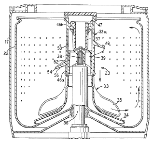
As seen in FTG. 2, the agitator means 23 has a lower
agitator element :33 with a skirt portion 34 which carries a
plurality of spaced, generally vertical agitator vanes 35. An
agitator drive shaft 36 extends through the lower agitator
element 33 and a portion of an upper agitator element 33a and is
secured to a cam anounting cylinder 37. The shaft 36 has a
splined portion 38 which is rigidly connected to an agitator
4


CA 02128768 2004-11-09
drive coupler 39 for oscillating the lower agitator element 33 in
the usual manner.
The upper agitator element 33a is composed of a plastic
material and, as illustrated in FIGS. 2-6, is hollow and has a
larger diameter end portion 46a in the area adjacent to the lower
agitator element 33, and a smaller-diameter upper portion 46b at
the upper end thereof. As best illustrated in FIG. 2, the lower
end of the upper agitator element 33a is received in overlapping
relationship with the upper portion.of the lower agitator element
33. The agitator drive shaft 36 extends up through the upper
agitator element 33a and is mechanically coupled thereto through
a one-way drive mechanism such as a one-way clutch 47. An
exemplary clutch is disclosed in U.S. Patent No. 4,719,769,
assigned to the assignee of the present invention.
The outer periphery of the upper agitator element 33a is
provided with vane means 49 for urging clothes downwardly. A
continuous helical vane 49 coaxial with the axis of rotation of
the lower agitator element 33 is shown extending outwardly from
the cylindrical wall of the upper agitator element 33a down the
length of the upper agitator element 33a and terminating short of
the vertical agitator vanes 35 for urging or deflecting clothes
downwardly.
The vane means 49 attaches to a barrel portion 50 of the
agitator at a root end 52 and, as seen in cross section, extends
downwardly and outwardly to a tip 54. Thus, a bottom surface 56
of the vane is shaped so as to provide an undercut or recessed
space 58 between the tip of the vane 54 and the agitator barrel
50. As items to be washed are engaged by the vane means 49, this
undercut shape of the lower surface 56 will retard~the items from
5


:y,
i
2~~~'~68
PA-7132-O-AW-USA
moving radially outwardly relative to the vane means 49 and will
enhance engagement between the items and the vane causing the
items to be move downwardly as the vane is rotationally driven
and to prevent the items from moving away from the agitator
either as it moves or when it is at rest.
With the arrangement shown in FIGS. 2-6, the upper agitator
element 33a is positively driven through the one-way clutch 47
only when the agitator drive shaft 36 is moved in a counter
clockwise direction. Under a fu1 1 r-..1 r,+-rP~ ~ "a,a T..ro"
agitator drive shaft 36 moves in a clockwise direction, the one-
way clutch 47 allows the upper agitator element to remain
relatively stationary due to the frictional drag placed thereon
by the water and the clothes within the basket.
Thus, there is a substantially automatic sensing of the
magnitude of the clothes load to provide incremental rotation
under significant clothes load conditions. This incremental or
intermittent rotation of the upper agitator element 33a with a
large clothes load provides a double action and causes the
helical vane 49 to act as an auger and thus auger or urge the
clothes downwardly along the upper agitator element into the
oscillating vertical agitator vanes 35 which move the. clothes
radially outwardly toward the periphery of the basket 22, then
upwardly and inwardly toward the upper agitator element 33a, all
is indicated by the arrows shown in FIG. 2 of the drawings. This
creates a highly desireable generally toroidal rollover movement
or action which subjects the clothes to intimate contact with the
washing liquid and to effective scrubbing action from the lower
agitator element.
6


2 i'~~'~~i~
PA-7132-O-AW-USA
Applicants have conducted tests on a vane having this
construction to determine the frequency of rollover of clothing
articles placed within the wash ba~;ket during a wash cycle and
have compared the results to a test utilizing an agitator
construction such as that disclosed in U.S. Patent No. 3,987,651
where the vanes project horizontally, and have found that the
vane construction disclosed herein provides a greatly enhanced
rollover rate with the improved ratio increasing as the size of
the clothes load being washed increases up to at least a 1000
increase. Thus, since washability is improved by increasing the
rollover rate, this invention permits an enlarged clothes load to
be washed in a washer having similar basket size and agitator
constructions and would allow for a shorter wash cycle in order
to result in a similar level of dirt removal as is provided in
currently available washers.
For example, a washer that typically was rated for an 18
pound maximum load could now easily handle a 20 pound load and
provide the same or an improved level of washability.
A modified form of an upper agitator element 60 for use in~
the present invention is illustrated in FIGS. 7-11 of the
drawings. These figures illustrate the upper agitator element 60
having a helical vane 62. A lower surface 64 of the vane is
contoured so as to have a plurality of wedge shaped steps 66
formed thereon. F~ach step has a substantially vertical wall 68
on a side leading away from the direction of rotation of the
upper agitator element 60 (down the slope of the helical vans 62j
and a ramp wall 70 on a side leading toward the direction of
rotation. This shape for the lower surface 64 will retard the
items being washed from moving upwardly along or with an
underside of the helical vane as the vane is rotated. Thus, the
7


' ~i
, " 21~~"~~~
PA°7132-O-AW-USA
items will be caused to move downwardly by the vane as it is
rotationally driven and the items will be prevented from moving
upwardly relative to the agitator and vane when the agitator is
stationary.
This arrangement has also been tested and has been found to
increase the rate of rollover relative to that provided by
presently available structure such as that disclosed in U.S.
Patent No. 3,987,651.
Of course, the upper agitator may be provided with both
surface contours for the vane, that is, the lower surface of the
vane may be sloped downwardly and outwardly and one or more steps
may be provided to increase the rate of rollover above that
achieved by using only one of the described surface contours.
As is apparent from the foregoing specification, the '
invention is susceptible of being embodied with various
alterations and modifications which may differ particularly from
those that have been described in the preceding specification and
description. It should be understood that I wish to embody
within the scope of the patent warranted hereon all such
modifications as reasonably and properly come within the scope of
my contribution to the art.
8

Representative Drawing
A single figure which represents the drawing illustrating the invention.
Administrative Status

For a clearer understanding of the status of the application/patent presented on this page, the site Disclaimer , as well as the definitions for Patent , Administrative Status , Maintenance Fee  and Payment History  should be consulted.

Administrative Status

Title Date
Forecasted Issue Date 2006-04-25
(22) Filed 1994-07-25
(41) Open to Public Inspection 1995-03-01
Examination Requested 2001-04-26
(45) Issued 2006-04-25
Expired 2014-07-25

Abandonment History

There is no abandonment history.

Payment History

Fee Type Anniversary Year Due Date Amount Paid Paid Date
Application Fee $0.00 1994-07-25
Registration of a document - section 124 $0.00 1995-01-20
Maintenance Fee - Application - New Act 2 1996-07-25 $100.00 1996-06-19
Maintenance Fee - Application - New Act 3 1997-07-25 $100.00 1997-06-24
Maintenance Fee - Application - New Act 4 1998-07-27 $100.00 1998-06-16
Maintenance Fee - Application - New Act 5 1999-07-26 $150.00 1999-06-16
Maintenance Fee - Application - New Act 6 2000-07-25 $150.00 2000-06-19
Request for Examination $400.00 2001-04-26
Maintenance Fee - Application - New Act 7 2001-07-25 $150.00 2001-06-15
Maintenance Fee - Application - New Act 8 2002-07-25 $150.00 2002-06-18
Maintenance Fee - Application - New Act 9 2003-07-25 $150.00 2003-07-14
Maintenance Fee - Application - New Act 10 2004-07-26 $250.00 2004-07-06
Maintenance Fee - Application - New Act 11 2005-07-25 $250.00 2005-07-05
Final Fee $300.00 2006-02-09
Maintenance Fee - Patent - New Act 12 2006-07-25 $250.00 2006-06-30
Maintenance Fee - Patent - New Act 13 2007-07-25 $250.00 2007-07-03
Maintenance Fee - Patent - New Act 14 2008-07-25 $250.00 2008-06-30
Maintenance Fee - Patent - New Act 15 2009-07-27 $450.00 2009-06-30
Maintenance Fee - Patent - New Act 16 2010-07-26 $450.00 2010-06-17
Maintenance Fee - Patent - New Act 17 2011-07-25 $450.00 2011-06-08
Maintenance Fee - Patent - New Act 18 2012-07-25 $450.00 2012-06-14
Maintenance Fee - Patent - New Act 19 2013-07-25 $450.00 2013-06-12
Owners on Record

Note: Records showing the ownership history in alphabetical order.

Current Owners on Record
WHIRLPOOL CORPORATION
Past Owners on Record
PINKOWSKI, ROBERT J.
Past Owners that do not appear in the "Owners on Record" listing will appear in other documentation within the application.
Documents

To view selected files, please enter reCAPTCHA code :


To view images, click a link in the Document Description column. To download the documents, select one or more checkboxes in the first column and then click the "Download Selected in PDF format (Zip Archive)" or the "Download Selected as Single PDF" button.

List of published and non-published patent-specific documents on the CPD .

If you have any difficulty accessing content, you can call the Client Service Centre at 1-866-997-1936 or send them an e-mail at CIPO Client Service Centre.


Document
Description 
Date
(yyyy-mm-dd) 
Number of pages   Size of Image (KB) 
Description 2004-11-09 8 335
Representative Drawing 1998-03-02 1 20
Cover Page 1995-05-13 1 79
Claims 1995-05-13 6 266
Description 1995-05-13 8 476
Claims 2004-11-09 8 283
Claims 2005-07-25 6 164
Representative Drawing 2005-09-14 1 22
Abstract 1995-05-13 1 24
Drawings 1995-05-13 3 143
Cover Page 2006-03-22 1 54
Correspondence 2006-02-09 1 28
Assignment 1994-07-25 7 269
Prosecution-Amendment 2001-04-26 2 112
Prosecution-Amendment 2004-05-18 3 123
Prosecution-Amendment 2004-11-09 13 498
Prosecution-Amendment 2005-01-25 4 145
Prosecution-Amendment 2005-07-25 10 358
Fees 1996-06-19 1 59