Note: Descriptions are shown in the official language in which they were submitted.
" ~93/1~99~ 2 1 2 8 7 8 ~ PCr/~S92/0~6~5
STOR~OE U~IT FOR COM
Field of the Invention
The present in~ention relates to units for
storing compact discs and the like employing the
conventional Sony/Philips jewel box which has a standard
constr~ction well known in the art.
Backqround of the Invention
Numerous proposals have been made in this art
for storage units in which a CD hold~r is mo~able in and
out of a housing. For exampla, U.S. Patent 4,760,502
(Ackeret) discloses a storage container in which CD's
are stored on a platform which is slideable in and out
of a housing and has a spring-loaded front which drops
down to give access tv the CD when the platform is in
the out position. ~.S. Patent 4,678,245 (Fouassler)
discloses a storage device in which discs are slid i~
~: and out o a housi~g on horizontal rail pxo~ided on the
:~ side walls of the housing. U~S. patent 4,702~369
~:~ discloses a storage container similar i~ appearance to a
co~ventional ~ewel box, but in which, in addition to a
: 25 hinged lid, the:box has an open front allowing an inner
disc-receiving, member to slide out through the front of
~ the box. ~ ~
': ~ Ob~ects of.the Invention
~: : 30 It is~an object of the invention to provide a
storage unit for CD's, which make use of con~entional C~
ewel boxes, and in which the jew~l boxes open
: automaticalIy when partislly withdrawn from the unit~
q ~ .
Summary_of the Inventivn
~ The present invention provides a ~torage unit
; f for co~pact discs and the like comprising an essentially
rectangular housin~; side walls of said housing ; a
plurality of sled means mounted within the housing on
. ~ ~ .. . .
~93/14~8 21~ ~ 7 ~ O PCT~US92/oO65~ ~;
which jewel boxes for compact diæcs can be mounted, in
use; track m~ans on the side walls with which said sled
mean~ are movably engaged to pennit individual sleds to
be moved in and ou~ of the unit; and means ~or opening
the lid of a ~ewel box mou~ed on a sled when tha`t ~led
is drawn forward and.moved partially out of the unit~
Brief De~crip_ion of the Drawinqs
Th~ invention will now be descri~ed by way of
example only, with reference to the accompanying
drawings, in which:
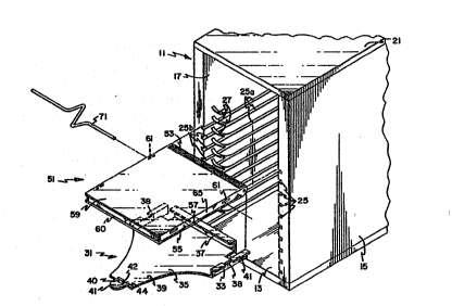
Figure 1 is a front perspective view of a
st~rage unit for CD's embodying the invention
showing one of the sleds and i~ associated
jewel box partially withdrawn fro~ the unit and
explod~d to revea~ detail;
ure 2 is a pe~spective view of the jewel box
and sled shown in Figure 1 î
Figure 3 is a vertical section on the line 3-3
in Figure 2,
: Figure~4 i~ a vertical side elevation showing
part:of the unit shown in Figur~ 1~ with one
side wall omi~ted to rsveal interior ~etail and
showing one of the sleds and its associated
j~el box paxtially wi~hdraw~ from the unit;
: Figu~e 5 is ~a vertical section on the line 5-5
in P~gure 4;
Figur~ 6 is a perspective vie~ showing a detail
of the unit in Flgure 1, and
Figure 7 is a front perspective view of an
- alternative design of storag~ unit embodying
~he invention.
Description of Preferred Embodimen~s
: 35 A storage unit for compact discs, such as 5"
; ~ audio discs, comprises an essentially box-shapedr i.eO,
; rectangular in its horizontal cro~s-section, housing 11
. :
~ ~93/1~8 2 1 2 8 7 ~ O PCT/US92/~0655
con~îs~ing of a base 13, side walls 15 and 17, a reax
wall (not ~hown) and a ~op wall 21. The rear wall may
be removably secured, as by screws (not shown), for a
purpose discussed below. ~he front face of the unit i~
open in this embodiment of the invention, though i't will
be appreciated that a removable front wall, or a hinged
front wall that could be opened and closed could be
provided, if desired.
The side walls 15 a~d 17 are provided with a
plurality of registering paixs of parallel grooves 25,
each groove 25 in the side wall 15 being aligned with a
corresponding groove in the side wall 17. The grooves
25 are open-ended at the back of the walls 15 and 17 and
each consists of a first portion 25a which extends from
the back o ~he wall substantially horizo~tally. The
initial parallel portion 25a of each of th~ grooves 25
i~ at lea~t ~" long. After khe initial ssctions 25a,
and groo~e 25 divides into a portion 27 which curv~s
upwardly and away from the horizontal plana con~aining
~0 the first groove portion 25a and a portion 25b which is
a continuation of the initial portion 25a and i~
substanti~lly horizontal. For reason~ discussed below,
each upwardly curved groove portion 27 ix ~ubstantially
deeper than ~he groove portions 25a and 25b.
:Figures ~ and:3 show one of a plurality of
~leds 31 ~hat are~mounted in the housing 11. ~ach sled
: 31 compri~es laterally:extending runners 33t which slide
in the~grooves 25,:enabling the sleds 31 to ~e moved
into and out of the housin~ 11. Each sled 31 comprises
a base 35, a rear L-shaped portion 37 extending upwardly
from the rsar of the base 35, left and righ~ side
portions 38 upstanding from the sides of the base 35 and
~: a forwardly projecting yok~ portion 39, which providesr
: at its forward end, a t~b 41 which the user of the unit
:~ 35 may grasp to remove the sl~d 31 in and out of the
hou~ing 11. A resili~nt retaining latch 40 is provided
on the ront of tbe yoke portion 39. A5 best seen in
wog3/l4~g 2 1 2 8 7 8 0 PCT/US92/00$5' 5
Fig. 1, the latch 40 extends perpendicularly to the base
35 of the sled 31 and has a ramped upper ~urface 42 and
8 retaining face 4~.
The runners 33 are provided by laterally
projecting flanges 41 extending ~rom the ide po~tions
39. As seen in Figure 2, the side portions 39 a~d
flanges 41 exkend approximately 2 1/4" forward from the
rear of the sled 31 and have omitted rBgions 43 about
1/2" long, in regi~ter, on either side of the ~led 31,
starting about 1 1/4" from the rear of the sled 31.
As best seen in Figure 1, a standard CD jewel
box 51, the construction of which is well known in the
art~ is mounted on each sled 31. The base 5S of the
jewel box 51 is mounted on the base 35 of the sled with
hinged edge 53 o~ the jewel box 51 accommodated within
the channel formed by the base 35 and rear L-shaped
~`; portion 37 of the sled 31. The side portions 38 of the
sled 31 extend along the side walls 57 of the jewel box
51 and are sp~ced a distance sufficient from those sides
57 to enable the lid 59 of the ~ewel ~ox 51 to open and
~ close without obs~truction. The front lip 6Q on the base
I S5 of the jewel box 51 is retained by the retaining
'~ latch~40 to hold down the front of ~he jewel box 51 on
the base 35 of the sled 31.
The openings formed by the omitted regions 43
: are in register with a pair of openings 61 in the lid 59
- of the jewel box 51 adj~cent to one of two pairs of ears
:'
~: 63 (seen in Fig. 3, but omitted from other Figures for
1~ clarity) that extend inwardly f~om the side wall 65 of
the lid 59 tv provide means for mounting a printed card
,~ gi~ing information about the content of the CD to be
~;: stored~in the jewel box 51.
~ - A flexible,:compressible rod 71, o circular
: crc,ss-section, a length greater than the width of the CD
3~ jewel box 51, extends through the openings 61 with its
~: ends projecting beyond the sled side portions 39 into
one pair of the grooves 27. As illustrated in Figure 2,
,
, .
~1 :
~93/14g98 2 12 8 7 ~ Q P ~/USg2~0655
the rod 71 may have ~-shaped central portion and be ~de
of a resilient material~ such as the plastic material
Delrin .
To load CD's into the unit, a plurality of
onventîonal jew21 boxes 51 are mounted each on a ~l~d
~5 as discus~ed above. One ~led 35 is now inserted into
the housing from the front with the runners 33 ~liding
into the pairs of open ends of the groove portions 25b.
The flexible rod 71 is next compressed ~o allow its ends
to enter into the ~roove portions 25b. A~ the sled 35
is pushed back into the unit, the rod 71 eventually
reaehes the deeper por~ion 25a of ~he groo~e 25l
wh0reupon the rod 71 re-extends to its full length.
When the sled 35 is pulled forward, the rod 71, now
extended, cannot ~nter the shallow groo~e portion 25b
and inste~d, follows the groove portion 27. In an
alternati~e form of ~he invention, the rod 71 is non-
compressible and the sled~ 35 are loaded into the u~it
by removing its rear wall and inserting the runners 33
and rod 71 into ~he open r~ar ends of thP grooves 2~o
When the desired number of jewel boxes 51 and sleds 35
has been ~oaded in tQ the housing, the rear wall 19 is
: replaced, securing the je~el boxes 51 against removal
from the hou~ing 11.
After loading, the-tab 41 of each sled can be
gr~sped:from the fron~ of the housing 11 and by pulling
: on a particular ~ab~41 a selected jewel box 51 is moved
:: froward partially through the open front Qf the housing11, cau~ing the lid 59 to open to give acc~ss to the CD
30~ therein as described below~
If the sled 35 is initially fully within the
~: housing 11, as the~sled 35 moves forward, the runners 33
: and the rod ~1 slide initially alon~ the groo~e portion
: 25a. While the rod 71 moves along the initial section
25a of the groove 25, the lid 59 of the jewel case 51
remains closed. When the rod 71 reache~ th~ div~rgence
between the groove portion 27 and 25b, it is forced to
.
WO93/149g~ PCT/US92/0065
enter the portion 27 because the portion 25b is not
sufficiently deep ~o accommodate it. As the rod 71
s~arts to travel along the curved portion 27, it is
fo~ced upwardly by engagement with the ramp constituted
S by the portlon 27. As the runners 33 and L-shape~ réar
portion 37 of the sled 35 hold the base 55 of the jewel
box 51 down/ the upward motion of the rod 71 exert~ a
force on the lid 59 of the i~wel box 51, s~parating it
from the base 551 giving access to the CD stored in the
jewel box 51.
When the sled 35 is pu~hed back into the
housing 11, the lid 59 closes as ~he rod 71 travels back
down the groove portion 27.
An alternative form of the invention is shown
in Figure 7. The alternative form is subskantially
similar to the form shown in Figures 1 through 6 and
like parts have been given the same reference number~.
In the unit illuskrated in Figure 7, however, the
laterally ext~nding flanges 41 that provide the runners
33 are locat~d along the bottom of the sled side
portions 39, so as to b0 substantially below the
horizontal plane in which the rod 71 is disposed.
In this~alternative for~, vertically separa~ed
~ pairs of grooves ~5 nd 27 are provided, wit~ the groove
: 25 27 for the rod ~1 spac~ed above the associated groove 25
~: for the runne~s~:33. The groove 25 is essen~ially
:~ horizontal for it~ entire~length. The groove 27 has an
initiall rear, portion 27a which is horizontal and
parallel to the groove 25 and an upwardly cur~ed forward
: 30 portion 27b. The groove 27 is deeper than the groo~e 25
so that the rod 71 cannot enter a groove 25, bu~ must
~; follow the ramped groove 27, even where the two
inter~ect.
., .
0: :
,