Note: Descriptions are shown in the official language in which they were submitted.
212943
SHEATHED STEEL PIPE WITH CONDUCTIVE PLASTIC RESIN
BACKGROUND OF THE INVENTION
1) Field of the Invention:
This invention relates in general to a tubular
member as the building block to make structures, and
particularly to such a member composed of a steel pipe
sheathed with conductive plastic resin.
2) Description of the Prior Art:
Structures, such as gravity-feed chute rack storage
units and roller conveyors are made of steel pipes
having with a small wall thickness and a diameter of 28-
32 millimeters, sheathed overall with an approximately
1 millimeter-thick film of plastic resin mixed with
carbon black as the conductive additive to release
electrostatic charge that may occur in the structure
from operation. In typical applications, these conven-
tional pipes may be made of SPCC-1 steel with a wall
thickness of 0.7 millimeter.
However, the prior-art sheathed steel pipes with
conductive plastic resin have been found to pose
problems. For one, carbon black normally used as the
conductive material for the film layer is expensive and
its black color generates limitations when designers
try to give a pipe structure decorative appearance. In
addition, the film layer of carbon black does not resist
impact well and easily fall from the sheathed surface.
To illustrate, if the width of carbon black forming
is less than 5 millimeters, the pipe fails to show
sufficient conductivity to prevent electrification.
Above 15 millimeters, the pipe costs too expensive and
gives poor appearance due to its black tone.
It was these drawbacks of the conventional sheathed
steel pipes with conductive plastic resin that gave rise
to the present invention.
SUMMARY OF THE INVENTION
It is a primary object of the present invention to
CA 02128943 2000-04-18
2
provide a sheathed steel pipe with conductive plastic
resin which is not expensive and can also give colorful
appearance. The pipe is sheathed overall with a film of
synthetic resin that is tinted in greed or ivory. A
narrow strip of plastic resin mixed with carbon black as
the conductive additive is longitudinally formed along
the length of the pipe, over the film forming, to make
the pipe conductive to prevent electrification.
In an aspect of the present invention, there is
provided a sheathed tubular body constructed from a
plurality of sheathed pipes comprising: a plurality of
sheathed steel pipes; each of said steel pipes being
sheathed with a film of a plastic resin; at least two of
said pipes being parallel to each other, and each of said
pipes has at least on.e longitudinally and radially
extending rib at an outer surface of each of said pipes;
said ribs being integral with said film of plastic resin;
said pipes positioned whereby each rib of one pipe is
proximal with each rib of another pipe; a strip of
electrically conductive resin being integral with said
film of plastic resin of each of said pipes; said
sheathed steel pipes being capable of being connected
through said strip to ground to prevent electrostatic
charge from accumulating on the sheathed steel pipes
during use.
BRIEF EXPLANATION OF THE ACCOMPANYING DRAWINGS
FIG. 1 is a perspective view of a sheathed steel
pipe with conductive plastic resin designed in accordance
with a first preferred embodiment of the present
invention;
FIG. 2 is a perspective view of a gravity-feed
chute-rack storage unit constructed into a structure of
CA 02128943 2000-04-18
2a
sheathed steel pipes of FIG. l, designed to shelve
printed-circuit boards;
FIG. 3 is a perspective view of a sheathed steel
pipe of a second preferred embodiment according to the
present invention;
FIG.4 is a perspective view of a section of a roller
conveyor using steel pipes of FIG. 3, showing its core
components;
FIG. 5 is a cross-sectional view of the part of the
structure of FIG. 4;
FIG. 6 is a perspective view of a sheathed steel
pipe of square cross section with conductive plastic
resin according to a third preferred embodiment of the
present invention;
FIG. 7 is a perspective view of a sheathed steel
pipe of square cross section as a modified form of FIG.
6;
FIG. 8 is a perspective view of a sheathed steel
pipe of square cross section according to a fourth
preferred embodiment of the invention; and
FIG. 9 is a perspective view of a sheathed steel
pipe of square cross section as a modified form of
212813
FIG. 8.
DETAILED DESCRIPTION OF THE INVENTION
Preferred embodiments of this invention will be
- described in full detail in conjunction with the
accompanying drawings.
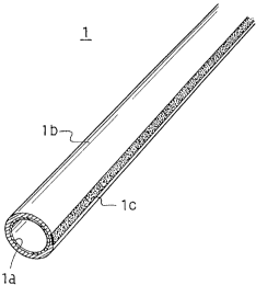
In FIG. 1, a sheathed steel pipe with conductive
plastic resin 1 manufactured according a first preferred
embodiment of the present invention is shown.
The tubular body la is coated externally with an
approximately 1-millimeter film lb of a plastic resin
such as Acrylate Styrene Acrylonitrile copolymer (ASA).
In addition, the tubular body la has a strip of syn-
thetic resin lc formed over the longitudinal length of
the resin film lb along the entire length of the tubular
body la.
After sheathing of the resin film lb, the pipe
1 ranges in diameter between 28 millimeters and 32
millimeters.
The resin film lb may preferably be tinted in green
or ivory to give decorative appearance.
The resin strip lc may preferably comprise a con-
ductive plastic resin, such as Acrylonitrile Butadien
Styrene copolymer (ABS) mixed with carbon black as the
conductive additive, and measure 15 millimeters in width
and 0.5 millimeter in thickness. The conductive resin
strip lc and the plastic resin film lb may preferably be
formed integrally by press extruding.
The aim of the conductive strip lc is to release
the electrostatic charge that may occur in the steel
pipes l, grounding the pipe structure in which steel
pipes 1 are connected with their conductive resin strips
lc aligned end-to-end.
A plurality of vertical and horizontal steel pipes
1 may be connected and assembled into a gravity-feed
flow-rack storage unit to shelve printed-circuit boards,
as shown in FIG. 2.
The storage unit comprises a rack framework 2
212~9~~3
4
including a pair of upright sides, each build with a
number of steel pipes 1 jointed end-to-end through
largely L-shaped corner joints 3a, 3b, 3c and 3d which
should be made of conductive metal or conductive plastic
resin material, into a trapezoid.
The framework 2 may be supported on casters 4 to
make the storage unit easy to move.
A plurality of T-joints 6, which are also made of
conductive metal or conductive plastic resin material,
couple the paired sides 5 to form the upright front and
rear sides of the storage unit in which the steel pipes
1 are connected end-to-end with a plurality of T-joints
7a and cross joints 7b that are made of conductive metal
or conductive plastic resin material.
With this arrangement, the front side of the
storage unit, as shown in FIG. 2, has a plurality of
substantially rectangular frames composed of horizontal
and vertical steel pipes 1 and joints 7a, 7b between the
trapezoidal sides 5.
The rectangular frames form ports 8 through which
printed-circuit boards are loaded or unloaded out of the
chute storage unit.
Each loading/unloading port 8 has therein a layer
of leveled pairs of chute rails 9 that extend between
the front and rear sides of the storage unit and tilted
downward toward the front side to keep printed-circuit
boards P in the manner of gravity-feed storage. In the
drawing, the guide rails 9 are shown on the one side of
the pairs alone for brevity's sake. With this arrange-
meat, separate loading/unloading ports 8 in a chute
storage unit may be labeled to hold different kinds of
electronic boards P.
In addition, each loading/unloading port 8 is
provided with a detection lamp 10 that may preferably
be mounted at a mid-point in the top pipe of the port,
v~~hich is lit up to help storehouse workers located
particular ports 8.
212893
Preferably, a pair of a photoelectric scanner and
a mirror, both not shown, are installed at aligned
locations across the loading/unloading port for each
pair of chute rails 9.
5 The associated scanner-and-mirror combination
detects the loading or unloading of a printed-circuit
board P as the board blocks the beam from the scanner
to the mirror when a warehouse worker is attending at
a particular port 8. The scanners and the detection
lamps 10 are connected through cables, not shown, to a
central computer program, not shown, which keeps track
of loadings or unloadings for a chute storage unit, and
energizes a buzzer, not shown, to warn if an attempt is
made to access the wrong port 8.
Moreover, in the bottom horizontal pipe section
1 of one of the side trapezoids 5 is provided with a
largely inverted U-shaped grounding terminal 12 with
a lead 11 to discharge static electricity that may
develop from friction by sliding printed-circuit boards
P against their respective chute rails 9 when they are
loaded or unloaded. In the structure of the illustrated
chute storage unit, the electrostatic charge that may
occur in the steel pipes 1 will be let to discharge
through the grounding terminal 12 and lead 11 via the
conductive joints 3a, 3b, 3c, 3d, 6, 7a, 7b.
It must be noted that, in this particular embodi-
ment, printed-circuit boards P are stored horizontally
between chute rails 9 that are mounted in the vertical
pipes of the loading/unloading ports 8.
However, this is a matter of choice, and in a
modified form of gravity-feed storage unit, the boards
P may be stored in vertical position, between the top
and bottom pipes 1 of the ports 8.
In addition, in an alternative modification, the
grounding terminal 12 and lead 11 may be replaced by
casters 4 that are made of an electrically conductive
plastic resin material to ground the chute storage unit.
21289t~~
6
This design would help avoid inconvenience on a
scattered storage floor where the trailing lead 11 can
be caught by obstructs when the storage unit has to be
wheeled around.
Referring then to FIG. 3, a second preferred
embodiment of a sheathed steel pipe with conductive
plastic resin 16 is shown. The pipe 16 comprises a pipe
body 16a having a thickness of 0.7 millimeter, sheathed
in the outside surface with a 1 millimeter-thick film
of plastic resin 16b, such as ASA.
A parallel pair of ribs 16c are longitudinally
formed along the entire length of the steel pipe 16,
and may preferably made integral with the resin film
16b. After sheathing of the plastic resin film 16b,
the pipe 16 measures a range of 28-32 millimeters in
diameter.
In an alternative modification, the pipe 16 may be
provided with a single longitudinal rib, instead of the
paired ribs 16c.
A strip of conductive synthetic resin 16d is formed
over the resin film 16b along the longitudinal length of
the pipe body 16a, and preferably measure 15 millimeters
in width and 0.5 millimeter in thickness. The resin for
the strip 16d may preferably be an ABS mixed with carbon
black as the conductive additive.
In addition, the conductive strip 16d and the plas-
tic resin film 16b may preferably be formed integrally
by press extruding. Furthermore, the strip 16d may be
formed parallelly with the paired ribs 16c, spaced from
the ribs for a distance of approximately one-fourth of
the circumference of the pipe body 16a.
The resin film 16b may be tinted in green or ivory
to give decorative appearance.
As with the earlier embodiment, the conductive
strip 16d causes electrostatic charge occurring in the
pipe 16 to discharge.
Referring next to FIGS. 4 and 5, a fragmental
218943
7
section of one of the roller frames of a roller
conveyor, using pipes 16a of FIG. 3, is shown in
perspective and cross-sectional views.
The roller conveyor consists of a pair of upright
side frame 17 between which a plurality of endless belt-
driven rollers are rotatably disposed in a horizontal
plane to carry cargoes on a moving surface, which may
comprises a steel pipe 16 of FIG. 3 and a sheathed steel
pipe with conductive resin material 18.
More specifically, the steel pipe 18 comprises a
tubular body 18a having a wall thickness of 0.7 milli-
meter, formed in the outside surface with a film of
synthetic resin 18b such as ASA approximately 1 milli-
meter in thickness. After sheathing the plastic resin
film 18b, the pipe 18 measures a diameter of 28-32
millimeters in diameter.
The resin film 18 may be tinted in green or ivory.
A single stretch of rib 18c is formed along the entire
length of the tubular body 18a, and may be formed
integrally by extruding with the film 18b. The
rib 18c is formed to have a size that allows the pipe
body 18a to snap into the paired ribs 16c of the steel
pipe 16 to form the roller frame 17 of dual pipes, to
thereby strengthen the structure of the roller conveyor.
When a pipe 16 and a complementary pipe 18 is
connected through their respective ribs 16c, 18c to form
a roller conveyor side frame 17, the conductive strip
16d should be made to face inwardly in the conveyor to
avoid immediate exposure of the conductive surface for
safety's sake.
In the roller conveyor side frame 17, the steel
pipe 16 may preferably be mounted to lay above the
complementary steel pipe 18, with or without supportive
legs, not shown, mounted below the frame.
A plurality of roller holders 19 made of a conduc-
tive composite resin material, which may be composed of
ABS mixed with carbon black as the conductive additive
CA 02128943 2000-04-18
8
and polycarbonate, are mounted along the steel pipe 16
of the conveyor side frame 17, at spaced intervals, on
both sides o:f the conveyor.
Each roller holder 19 has a base member 20 composed
of a C-shaped clutch 20a that snaps onto the steel pipe
16 and a largely U-shaped pocket 20b to removably
receive therein the end of a conveyor roller 22 through
an end member 21.
The end member 21 comprises a largely inverted
L-shaped engaging member 21a and a hub member 21b that
is mounted to extend perpendicular with the longitudinal
axis of the roller conveyor body. The pocket 20b is
engaged with the e:nd member 21 with the perpendicular
portion of the L-shaped member 21a inserted into the
vertical slip of the pocket.
The roller holder 19 holds the conveyor roller 22
rotatably in the pocket 20b of the base member 20. The
conveyor roller 22 is a tubular member 23 comprising a
steel pipe 23~a having a thickness of 0.7 millimeter, and
coated in the>. outs.ide surface with an approximately 1
millimeter-thick film of conductive synthetic resin 23b.
The conductivE=_ resin for the film 23b may be PE
mixed with carbon black as the conductive additive.
After pipe surface extrusion with the resin film 23b,
the conveyor roller 22 measures a range of 28-32
millimeters in diameter.
In addition, t:he conveyor roller 22 has an end cap
24 that is sized to fit into the pipe body 23 at the end
of the roller. The end cap 24 is made of the same
conductive resin that makes as the film 23b for the
roller 22. Also, t:he end cap 24 has an axial hole 24a
into which the hub 21b is inserted to enable the roller
holder 19 rotatably holds the roller 22 through the end
member 21.
A largely inverted-U shaped grounding terminal 26
is mounted around t:he steel pipe 16 to ground the roller
conveyor through a lead 25.
2128~4J
9
The end cap 24 may preferably be provided with a
pulley 24b that is concentrically mounted around the
periphery of the end cap. The pulley 24b is driven by
a drive pulley, not shown, through an endless belt of a
round or V-shaped cross section, not shown, passed about
the pulley 24b, to turn the conveyor roller 22 about its
axis.
Static electricity developed in the conveyor
rollers 22 as they turn will be discharged through the
grounding terminal 26 and lead 25 via the conductive
roller holders 19 and the conductive resin film 16d of
the steel pipes 16 that make up the roller side frames
17.
With roller conveyors thus built according to the
present invention, there will be little danger of injury
for factory operators at work or damage to the products
carried over the roller due to static electricity.
TABLE 1
Room Room Electrostatic potential (V)
Run temperature moisture This Conventional
No. (C) (o) invention conveyor
1 25 76 0 6000
2 26 71 100 - 200 5000 - 6000
3 26 76 200 4500
4 32 63 0 - 200 7600
5 32 63 100 - 200 10500
6 27 75 200 6000
7 27 60 200 - 300 8000
8 30 50 700 8000
9 32 57 200 5000
TABLE 1 shows the result of a series of testing,
carried out over a number of days under different
atmospheric conditions of temperature and moisture,
to compare the readings of electrostatic potential
_. 2i28~~j
occurring in a roller conveyor made of sheathed pipes
according to the present invention and that in a
conventional roller conveyor. The mean of measuring
electrostatic potential is used a model KSD-0102 digital
5 voltage gauge manufactured by Kasuga Denki KK.
The TABLE 1 shows how less electrostatic potential
was in the roller conveyor of sheathed steel pipes of
this invention, compared with the conventional conveyor.
In this particular embodiment, the roller side frames 17
10 uses a double-pipe assembly comprises conductive resin-
sheathed steel pipes 16 and resin film-sheathed steel
pipes 18 longitudinally bonded together by their ribs
16c, 18c. However, this design is a matter of choice,
and the side frames 17 may comprises a structure of
sheathed steel pipe with conductive synthetic resin 16
of FIG. 3.
In an alternative modification, the side frames 17
of a roller conveyor may be a dual-pipe structure built
of conductive resin-sheathed steel pipes similar to ones
1 depicted in FIG. 1 and complementary ribless resin-
extruded steel pipes laid parallel with the former.
The roller conveyor may not need to have conductive
resin-coated pipes 16 built into on all sides frames
thereof or the entire length of each side frame depend-
ing on the type of cargoes to be handled or the entire
mechanical structure.
In FIG. 6, a sheathed steel pipe with conductive
resin material 30, made according to a third embodiment
of the invention, is shown. The pipe 30 comprises a
pipe body of square cross section 30a extruded with a
film 30b of synthetic resin. A longitudinal strip of
conductive synthetic resin 30c is press-coated along one
side of the square pipe body 30a, which is integral with
the resin film 30b.
As a modified form of the resin-sheathed pipe 30,
a strip of conductive resin 32c is press-extruded on the
resin film 32b of the resin-sheathed pipe 32, along a
2128~~3
11
corner of the pipe body 32a in FIG. 7, instead of the
side of a pipe as shown in FIG. 6.
The aim and the manner in which the sheathed
conductive-resin layered square pipes 30 (FIG. 6), 32
(FIG. 7), along with their general dimensions, are
essentially similar to the round cross-section pipe of
FIG. 1, and will not be described here for brevity's
sake.
Referring to FIG. 8, a resin-sheathed square cross-
section pipe 34 includes a pair of ribs 34d bonded to
one side of the square tubular body 34a. The purpose
of the paired ribs 34d is essentially similar to that
of the paired ribs 16c of FIG. 3 and will here not be
discussed for brevity's sake. The pipe 34 also includes
a resin film 34b and a longitudinal conductive strip 34c
all of which are similar to the round pipe 16 of FIG. 3.
With respect to FIG. 9, a modified form of the
resin-sheathed square steel pipe 36 is shown, in which
a conductive-resin strip 36c is formed along a corner
of the square pipe body 36a. The pipe 36a also includes
a film of synthetic resin 36b that is integrally formed
by press extruding with the conductive strip 36c.
It will be clear from the above that a structure
made of sheathed steel pipes with conductive plastic
resin manufactured according to the invention is
grounded to discharge static electricity that may occur
in the structure. In addition, the pipe costs less
since the expensive carbon black, which is used as the
conductive material for grounding the pipe structure, is
coated only in a narrow longitudinal strip in the pipe
circumference, not the entire pipe external surface as
in conventional structure pipes. In addition, the pipe
according to the invention leaves a wider freedom of
color design for the pipe external surface since the
narrow conductive slip of black carbon leaves a wider
area to bring the pipe in a variety of tints of plastic
resin for attractive decoration.