Note: Descriptions are shown in the official language in which they were submitted.
2128946
pROC888 llldD l~ippARl~T08 FOR CONTROLLING 11 HYDR7~10LIC LIFT
~ACKGROLJND OF THE INVENTION
1. Ffeld of the Invent on
This invention pertains to a process and an apparatus for
the control of a hydraulic lift wherein a control device
produces control signals that are directed to a regulation
valve arrangement which in turn so controls the through-flow
of fluid under pressure that an elevator car is accelerated,
moves with a constant velocity and thereafter decelerates upon
the arrival of a shaft information signal which in turn
produces a brake-input or slow down initiation point.
2. Discussion of the Background of the Invention and Material
information
In such lifts, the drive velocity depends more or less
strongly on variations in car load and the temperature of the
hydraulic pressure medium, whereby the hydraulic pressure
flow, controlled via a regulation valve, changes
correspondingly so that an exact floor approach is not
possible. In order to correct this deficiency, shortly prior
to the arrival at the floor, the velocity is switched to a
small, constant creeping or levelling speed, so that the
height difference, caused via load and/or temperature changes,
can be compensated (see prior art Fig. 3). This, in turn,
leads to increasing operating and waiting times for users and
requires high energy usage. In hydraulic lifts, in addition
and as is well known, the length of the creeping speed is also
dependent upon load and temperature conditions.
German Patent Publication DE 36 38 247 teaches an
apparatus for a hydraulic lift according to which the
previously noted deficiencies are to be eliminated. This
apparatus utilizes a control device that produces output
signals defined by the velocity behavior of the lift, with
1
212894b
. ...
these output signals then being directed to a control valve.
The control valve, in turn, channels pressurized fluid, from
a source of fluid pressure, to or from a hydraulic drive
cylinder, in accordance with these output signals. In a
memory unit, connected with the control device via a computer,
reference velocity values are stored, which values correspond
with defined operating condition, which in turn are based upon
differing load~and/or temperature relationships. A sensing
element attached to the car obtains the actual velocity and
channels same, via a converter system, to the computer.
Therewith, a difference is obtained between the actual
velocity, measured during the acceleration phase, and a
predetermined reference speed, based upon which the computer
calculates a control velocity curve. This curve, in turn, is
stored and then utilized during the deceleration phase to
correct the actual velocity to the value of the previously-
mentioned reference velocity. In this manner, an exact and
quick approach to designated areas is to be achieved and the
operating time of the lift is to be reduced. However, this
control device, even though not utilizing a control circuit or
control for the adaptation of the slow down initiation point,
cannot operate without the use of a creeping or levelling
speed.
SUMMARY OF THE INVENTION_
The task or object of this invention pertains to a
process, and an apparatus for practicing the process, in the
manner of the preamble of claim 1, so as to permit a direct
floor approach without requiring a creeping speed.
One embodiment of this invention pertains to a process
for controlling a hydraulic lift having a control device, with
control signals (S) produced via the aid of a sensing element
in combination with a car of the lift, wherein these signals
(S) are directed to a regulation valve arrangement, with the
regulation valve arrangement so regulating the through-flow of
2
,~ 212894b
pressurized fluid that the car is accelerated upwardly or
downwardly, is moved at an operational speed and is
decelerated upon the input of a slow down point, signalled via
a shaft information, the process comprising: r a c a f v i n g
position signals fn the sensing element and controlling the
car in a position-dependent manner during the deceleration
phase wherein, upon the inputting of a drive command,
determining and storing a first value (S1) of the control
signal (S), at the start time of the car; storing a second
value (S2) of the control signal (S) of the control device
upon the inputting of a slow down signal; constituting a
control region (CS), based on the relationship CS = S2 -S1 +
H, wherein S1 is the first value of the control signal, S2 is
the second value of the control signal and H is a previously
determined hysteresis value; producing, during the
deceleration phase, actual values (si) from the position
signals; allocating a percentage value (tS) of the control
region (CS) to each actual value (si); multiplying the
percentage values (~S) with the values of the control region
(CS); and determining, with the thus achieved product, the
extent of the control signal (S) utilized during the
deceleration phase.
In a further embodiment of the process of this invention
a signal, reproducing the location of a main valve piston,
obtained via a spring coupled to a piston rod, serves as a
feedback signal.
Another embodiment of the process of this invention
further includes adding to a product designated as the control
signal, a control deviation (CO) and a pilot control signal
(SO), wherein CO is determined via the relationship CO = S2 -
SO - CS, and wherein S2 is the second value of the control
signal, SO is the pilot control signal and CS is the control
region, with the thus ascertained sum representing the control
signal (S), that is utilized during the deceleration phase.
3
2128946
An additional embodi'ent of the process of this invention
further includes determining a hysteresis value (N) during a
learning trip, whereby the control signal (S) is increased
until the velocity achieves a predetermined value, wherein,
upon reaching the predetermined value, measuring and storing
the strength of the control signal (S), thereafter increasing
the control signal (S) and after a while again decreasing the
control signal, until again reaching the predetermined value
of the velocity , again measuring the strength of the control
signal (S), with the difference between the two measured
values being the.hysteresis value (N).
Still a further embodiment of the process of this
invention further includes determining the pilot control
signal (SO) during a learning trip, wherein a spool of the
regulation valve arrangement is impacted with an increasing
stepped control signal (S) until the car moves and wherein the
thus obtained control signal is reduced by a constant value
and stored as a pilot control signal(SO).
Yet another embodiment of the process of this invention
further includes determining a boundary control signal (SL)
during a learning trip, whereby a spool of the regulation
valve arrangement is impacted with an increasing, stepped
control signal (S) until the velocity of the car no longer
increases.
A different embodiment of the process of this invention
further includes the car proceeding in an unregulated manner
in the phase before the deceleration phase whereby the velocity, in the
ascending direction, is limited by the configuration of at
least one of the hydraulic components of the hydraulic lift.
An additional embodiment of this invention pertains to an
apparatus for carrying out the process of this invention by
means of a control device controlling a regulation valve
arrangement and with a sensing element in combination with a
car, wherein the control device includes at least a tachometer
signal transducer, wherein the sensing element is connected to
the input of the tachometer signal transducer; wherein the
4
CA 02128946 2002-07-09
control device also includes a position controller having
an input connected with an output of the tachometer signal
transducer, with the tachometer signal transducer
outputting actual values (si), the position controller
having an output connected with the regulation valve
arrangement, during the deceleration phase; the position
controller including a table, the table storing allocations
of actual values (si) relative to percentage values (~S) of
a control region (CS), the position controller including a
multiplier, one input of the multiplier being connected
with the table while another input of the multiplier is
provided with the value of the control region (CS), With
the output of the multiplier forming the output of the
position controller.
In one aspect, the present invention provides a process
for controlling a hydraulic lift including a control device
and control signals produced by a sensing element
associated with a car of the lift, the control signals are
forwarded to a regulation valve arrangement for regulating
a through-flow of pressurized fluid to accelerate, upwardly
or downwardly, the lift car, the lift car is moved at an
operational speed and decelerated upon receiving a slow
down signal input from elevator shaft information, the
process comprising: receiving lift car position signals
from the sensing element and controlling a position of the
car during a deceleration phase occurring after the slow
down signal is input; issuing a drive command; determining
and storing a first value of the control signal at the
start time the drive command is issued; storing a second
value of the control signal upon receiving the slow down
CA 02128946 2002-07-09
signal; calculating a control region based on the following
relationship: CS=S2-Sl+H, wherein, CS represents the control
region; S1 represents the first value of the control
signal; S2 represents the second value of the control
signal; and H represents a previously determined hysteresis
value; producing, during the deceleration phase, actual
position values from the lift car position signals;
ascertaining a percentage value of the control region for
each actual position value; multiplying each ascertained
percentage value with the calculated value of the control
region; and determining an extent of the control signal
utilized during the deceleration phase.
In a further aspect, the present invention provides an
apparatus for controlling a hydraulic lift comprising: a
control device controlling a regulation valve arrangement;
a sensing element in combination with a lift car; said
control device including a tachometer signal transducer;
said sensing element is connected to an input of said
tachometer signal transducer; said control device further
including a position controller having an input connected
with an output of said tachometer signal transducer for
receiving actual position values, and having an output
connected with the regulation valve arrangement, during a
deceleration phase; said position controller including a
table associating actual position values with percentage
values of a control region and a multiplier having a first
and a second input, said first input of said multiplier
being connected with table, said second of said multiplier
provided with a value of said control region, and an output
5a
CA 02128946 2002-07-09
of said multiplier forming an output of said position
controller.
Further embodiments of this invention pertain to an
apparatus wherein the regulation valve arrangement includes
a stroke-force feedback, wherein the stroke-force feedback
is produced via a compression spring; and wherein the
control device utilizes a digital position controller.
In the manner set forth, the car is controlled in a
position-dependent manner during the deceleration phase and
for which purpose a drive-specific control region is
formed, the latter being subdivided into percentage values.
These percentage values in turn are recorded in tabular
form with reference to the measured actual values. Upon
the arrival of a specific actual value, the corresponding
percentage value is multiplied by the value of the control
region, which in turn forms the actual control signal used
during the deceleration phase. This latter control signal
is then directed to the regulation valve arrangement.
The advantages achieved by this invention are that the
operating and waiting periods are reduced; that the
temperature of the fluid pressure medium is heated less and
5b
',--
2128946
the consumption of energy is reduced. Via the suggested
direct floor approach, by the use of a regulation valve
arrangement having a simple constructional position feedback
system, an exact stop, without a level readjustment, is
achieved and, with reference to ride quality and minimal
operating time, achieves an optimal deceleration result. At
the same time, load and temperature variations will not
influence the stopping accuracy. It is also advantageous that
the acceleration of the car and the operation, at rated speed,
occur without regulation, the latter having a favorable impact
upon the efficiency of the hydraulic drive. An additional
advantage is in that the use of a regulation valve
arrangement, which during its use interacts with a control
device, permits the automatic determination of lift-specific
parameters during learning or self-teaching trips. Thus,
manual adjustments during the initial installation can be
avoided.
BRIEF DESCRIPTION OF THE DRAWINGS
The invention will be better understood and objects other
than those set forth above will become apparent when
consideration is given to the following detailed description
thereof. Such description makes reference to the annexed
drawings wherein throughout the various figures of the
drawings, there have generally been used the same reference
characters to denote the same or analogous components and
wherein:
Fig. 1 is a schematic representation of the apparatus of
this invention;
Fig. 2 is a schematic representation of a regulating
valve arrangement of the apparatus of to Fig. 1;
Fig. 3 is a velocity/time diagram of a prior art
hydraulic elevator;
6
--.
2128946
Fig. 4 is a velocity/time diagram and a control
signal/time diagram of a hydraulic elevator controlled by the
apparatus of this invention; and
Fig. 5 is a block-diagram illustration of a position
controller of the apparatus according to Fig. 1.
QETAILED DESCRIPTION OF THE PREFERRED EMBODIMENTS
With respect to the drawings it is to be understood that
only enough of the construction of the invention and the
surrounding environment in which the invention is employed
have been depicted therein, in order to simplify the
illustrations, as needed for those skilled in the art to
readily understand the underlying principles and concepts of
the invention.
In Fig. 1, numeral 1 designates an elevator car which can
be set into motion with a hydraulic lifting apparatus having
a piston 3 and a cylinder 4. This motion is transferred by
means of a cable 5 that runs over two rolls 6, secured on
piston 3; two rolls 7, secured on cabin 1 and a fixedly
secured roll 8, with car 1 being guided in elevator shaft 9.
A shaft switch 10, secured in shaft 9, a sensing element 11,
connected with car 1; and a lift controller or operating
control 12 are all operatively interconnected with a
preferably digital control device 20. Sensing element 11
includes a wheel that runs along a taut cable extending along
the length of .the shaft and provides .or outputs travel or
position signals in the form of pulse signals. Sensing
element 11 can function as described or function in other
mechanical ways as well as electrically or optically. A
regulating valve arrangement 13, to be described more
completely hereafter relative to Fig. 2, is electrically
interconnected with the output of control device or regulator
20 as well as being connected with hydraulic lift apparatus 2
7
r
2128946
and a source 'of fluid pressure, via hydraulic lines or
conduits.
Lift controller 12 conducts or channels drive inputs to
regulator 20. Brake input signals are channelled to regulator
20 by a regulator control system 21, which in turn forms a
portion of regulator 20. The brake signals originate from
shaft switches 10 which are arranged at predetermined spacings
or distances ahead of the floors or landings. Brake input
signals can also be carried by sensing element 11, in that,
for example, with a certain number of added or summed position
signals, equivalent shaft information is produced. Regulator
20 produces a signal S which is supplied to regulation valve
arrangement 13.
Regulator control system 21 is connected with a
tachometer signal transformer 22 which transforms the position
signals, supplied by shaft switch 11, into actual velocity
values vi or actual position values si. A speed regulator 23
is connected, on its input side, with that output side of
tachometer signal transformer 22 that outputs the actual
velocity values vi and with that output of a speed reference
value setting means or set value generator 24 that outputs
velocity set values VS, with set value generator 24 being
connected, on its input side, with regulator control system
21. Speed regulator 23 can, via an additional inlet,
connected with regulator control system 21, be reset or
started. Speed regulator 23 can take the form of a
conventional PID-controller. Numeral 25 designates a position
controller which will be described in more detail with
reference to Fig. 5, with position controller 25 being
connected, on its input side, with that output side of
tachometer signal transformer 22 that outputs the actual
position value si. Position controller 25 includes a table 26
within which allocations of actual position values si are
8
~
.-.
' ~ 2 ~ 2a 946
stored relative to percentage values ~S of a control region or
domain CS which will be described later with reference to Fig.
4. A switching device 27 is connected with the output of
regulator control system 21, the output of speed regulator 23,
the output of position controller 25 and the input of a DA
converter 28. .The outlet of position controller 25 can be
switched at the input of DA converter 28 by means of switching
device 27 upon the input of shaft information signalling-the
input or entry of a brake input point. The output of DA
converter 28 is connected with an amplifier 29, the output of
which also is the output of control device 20.
The regulation valve arrangement shown in Fig. 2 includes
two electro-hydraulic flow control valves 30, 30' of the same
type. The following description, pertaining to flow control
valve 30, regarding the control of the lowering process,
pertains in the same manner to mirror-image flow control valve
30' , regarding the control of the lifting of the car, with the
same but prime numerals being utilized for valve 30'.
A main valve piston 32 resides within valve chamber 31,
with the former having a piston rod 33 extending from its rear
portion. Surrounding piston rod 33, but without a functional
connection therewith, is a pilot valve 34, including an
electromagnet 35, with valve 34 being electrically connected
with the output of control device 20 shown in Fig. 1. Piston
rod 33 extends from the rear of pilot valve 34 and is equipped
with an abutment 36 at its rear, with a compression spring 37
being interposed between abutment 36 and pilot valve 34.
Compression spring 37 opposes the force of electromagnet 35. '
Via the use of compression spring 37, a closed control loop,
having an internal feedback within pilot valve 34, is
established. Pilot valve 34 is located in connection line or
conduit 38 and regulates the through-flow of hydraulic fluid,
9
2128946
with conduit 38 interconnecting a front chamber 39 and a rear
chamber 40 of valve chamber 31.
Valve front chamber 39 includes an inlet C connected with
variable passage or port 39.1 with an outlet T, the latter
terminating into tank or reservoir 42. Inlet C is connected
with cylinder 4 of lift apparatus 2. Valve rear chamber 40 is
also connected with reservoir 42 via drain line 41, with an
electromagnetic closing valve 44 being interposed in drain
line 41.
Regulation valve arrangement 13 operates via stroke force
feedback, that is the force of compression spring 37, which
represents the~position of main valve piston 32, is measured
and serves as a feedback or reaction signal. This achieves
that the force of electromagnet 35, that is the force of
control signal S, is proportional to the position or location
of main valve piston 32. This solution exhibits good dynamic
behavior, is inexpensive as well as being of simple
construction. Of course other, for example hydraulic,
electric or mechanical feed back systems could also be
utilized.
In fluid control valve 30', outlet T' of valve front
chamber 39' is also connected with reservoir 42. An inlet,
designated as P, is operatively connected with a motor-driven
pump 45 of fluid pressure source 14, with pump 45 having its
suction inlet within reservoir 42. Flow control valve 30'
does not require a closing valve in its drain line 41'.
Inlets C .and P are interconnected with a connecting
conduit 47 having a back flow check valve 48, the latter
acting in a manner so that the hydraulic medium of lift
apparatus 2 cannot flow back in the direction toward pump 45.
At rest or the non-operation of car 1, signal S is zero
and flow control valve 30 is closed by hydraulic pressure.
This parameter is achieved when pilot valve 34 is slightly
l0
2128946
opened so that valve chambers 39 and 40 are interconnected and
that the force.acting on the large rear surface of main valve
piston 32, in rear valve chamber 40, displaces piston 32 in
the direction toward front valve chamber 39. Closing valve 44
is closed both in the at-rest position of car 1 as well as
during the lift phase thereof, with flow control valve 30'
being open during the at-rest position of car 1.
Upon receipt of a call or input requesting descent or a
down trip, control device 20 initiates a signal S which
corresponds to the closed position of flow control valve 30,
that is that pilot valve 34 is opened to the extent that its
opening cross section exceeds that of drain line 41. During
the subsequent opening of closing valve 44, main valve piston
32 remains in its closed position even during drainage flow of
the hydraulic medium via drain line 41. Thereafter,
electromagnet 35 receives a proportional signal S', opposite
to signal S, which principally causes the following: The
force of electromagnet 35 opposes that of compression spring
37. When main valve piston 32, via the pressure differences
existing in chambers 39 and 40, is translated to the extent
that the through-flow of hydraulic pressure through connecting
line 38 is the same as that in drain line 41, the movement of
main valve piston 32 stops at that location until control
signal S is changed.
Upon an increase in signal S, that is upon a decrease in
signal S', this also decreases the opening cross section of
pilot valve 34 and main valve piston 32 is then moved, due to
the reduction in pressure, back into rear chamber 40. Passage
39.1 is then opened and the pressure medium then flows from
lift apparatus 2 into reservoir 42, whereupon car 1 descends.
Signal S increases until car 1 achieves the desired maximal
speed, with signal S remaining at this level until a brake
input signal is received. From this point on, signal S is
1i
2128946
again reduced, in a position-dependent manner, by control
device 20, whereby main valve pi ston 32 moves in the direction
of passage or port 39.i until it fully closes same so as to
bring car 1 to a stop. At this time, closing valve 44 is also
closed, with flow control valve 30' remaining open, in an
unchanged manner, during the descent of car 1.
Flow control valve 30' for the lifting of car 1,
functio»s principally in the same manner as flow control valve
30, however with the exception that signal S', for
electromagnet 35' is proportional to signal S. Upon receipt
of a call or input requesting ascent or lift, pump 45 is
actuated which then pumps pressurized fluid into reservoir 41
via front chamber 39' and port 39.1' . Thereafter, pilot valve
~34' receives a signal S' which causes the opening of
connecting line 38'. Thereafter, the pressure medium flows
from front chamber 39' to rear chamber 40'. At a specific rate
of signal S, the opening cross section of pilot valve 34'
becomes greater than that of drain line 41. This causes a
pressure rise within rear chamber 40' and main valve piston
32' then moves to the front thus reducing the opening of port
39. 1' . As soon as the pressure within chamber 39' exceeds the
pressure within lift apparatus 2, back flow check valve 48
opens and car 1 is set in motion. Upon the total closing of
port 39.1' the lift ascends at maximum speed.
The acceleration phase as well as the drive at the
nominal or operating speed can proceed without regulation.
During descent, the totally unthrottled capacity of pump 45
can thus be utilized, with the maximum speed of car 1 thus
being determined by the pump capacity. The descent speed can
be limited via a correspondingly measured aperture opening in
the drain line of lift apparatus 2.
The illustrated operative example utilizes two pilot
valve arrangements wherein only one is operative in each
12
2128946
direction of travel. A further operative variation utilizes
but one pilot valve arrangement for both directions of travel
so as to alternately control valves 30, 30'.
In the prior art, as represented in Fig. 3, v represents
velocity while t represents time. Depending upon the load and
the temperature of the hydraulic medium during the
deceleration phase, differing speed/time response curves A, B,
are obtained so that for an exact entrance or stop a creeping
velocity is required.
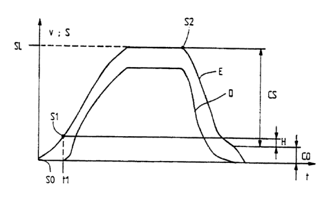
Accordingly, in Fig. 4 v and t again represent velocity
and time, wherein the velocity axis also corresponds to
control signal S produced by control device 20. A response
curve D represents the actual velocity progression while a
response curve .E represents the progression of control signal
S at the outlet of control device 20 during a trip of car 1.
In addition the following abbreviations are utilized:
SO, S1, S2 are defined values of control signal S;
CS is a control region;
g is a hysteresis value; and
CO is a control deviation.
As per Fig. 5, table 26 is connected with the input of a
multiplier 25.1, with table 26 being the means via which the
control signals, corresponding to the actual position values
si, for-regulation valve arrangements 13, are produced during
the deceleration phase. Multiplier 25.1 in turn, in each
instance, multiplies a percentage value ~S, corresponding to
the actual position value si', with the calculated value of
control region CS. For the improvement of the control yield,
the output of multiplier 25.1 is connected with the input of
an adder or accumulator 25.2, the latter adding the control
deviation CO and the pilot control signal SO to the product of
13
r
2128946
multiplier 25.1, with the accumulator outlet also taking the
form of the outlet of position controller 25.
The previously described control device 20 operates in
the following manner: Upon the receipt of a drive input, from
lift controller 12, the speed regulator 23 is reset or
activated via regulator control system 21 and the input of DA
converter 28 is switched, via switching device 27, to the
output of speed regulator 23. Car 1, during the acceleration
phase and during the trip, is controlled at a constant
velocity via the comparison of the actual velocity values vi
and the set or desired velocity values vs, whereby the control
signal S, at the output of control device 20, takes the form
or progression of response curve E in Fig. 4. Upon receipt of
drive command, car 1 is set in motion at start time point ti
and, at the same time, a first value S1 of control signal S is
accumulated or stored, as shown in Fig. 4. Once car 1
receives a brake input point, the respective shaft switch 10,
or sensing element 11, sends a shaft information to
regulator control system 21, whereupon the deceleration phase
is initiated. Thereupon, position controller 25 is activated
and its output 27 is switched to the input of DA converter 28
by means of switching device 27. At the same time period, a
second value S2, of control signal S, is stored and a control
region CS is calculated according to the relationship CS = S2
-S1 + H (Fig. 4), wherein S1 and S2 are the first and second
values of control signal S and H is a hysteresis value which
is ascertained in a manner to be described hereinafter.
Position controller 25 now functions in the manner, as already
described relative to Fig. 5, the percentage values ~S,
corresponding to the actual position values si, are multiplied
with the calculated value of control region CS and the control
deviations CO as well as the pilot control signal SO are added
thereto, wherein CO = S2 - SO - CS, as per Fig. 4. The thus
14
2128946
ascertained sum is channelled to amplifier 29 (Fig. 1) via
switching device 27 and DA converter 28, with this thus
ascertained sum then taking the form of the current actual
output signal S at the output of amplifier 29.
As already noted during the description of Fig. 2, at the
selected regulation valve arrangement 13, the setting of main
valve piston 32 is directly proportional to control signal S.
However, control signal S, as produced by speed regulator 23
is load and temperature-dependent up to the time period of the
brake input. ~ Since however the control region for the
deceleration phase is newly fixed in view of values S1, S2 and
H relative to the actual and constant-remaining (during the
trip) load and temperature conditions, an exact direct input
or approach can be achieved without requiring a level
readjustment.
The hysteresis value H is determined, during a learning
or self-teaching trip in the following manner: The control
signal S is increased until the velocity achieves a
predetermined or given value. Upon the attainment of this
given value, the strength of control signal S is measured and
stored. Thereafter, the signal is increased further and after
a while it is again decreased until the given velocity value
is again achieved. Then the strength of control signal S is
measured again and from the two measured values a difference
is derived which constitutes hysteresis value H.
Further lift-specific parameters that are in combination
with a direct entry or input, such as for example a pilot
control signal SO or a boundary or marginal signal SL can also
be determined during a learning or self-teaching trip.
Pilot control signal SO:
Pilot control signal SO achieves, on one hand, an
instantaneous descent start of the car after the start
. ."",.
2128946
command, on the other hand, via the use of pilot control
signal SO, the starting jolt can be significantly reduced.
For the determination of pilot signal SO, electromagnet 35 of
the regulation valve arrangement is impacted with an
increasing stepped control signal S until the car moves. The
thus determined control signal is reduced by a constant value
and stored as a pilot control signal. Upon receipt of a drive
command, the regulation valve arrangement 13 is directly
impacted or exposed to pilot control signal SO.
Boundary or marginal control signal SL:
The boundary or marginal control signal SL is that
specific control signal S, with which main valve piston 32, of
regulation valve arrangement 13, achieves its end or rest
position. Control device 20 operates in such a fashion that
the value of control signal S can never exceed the value of
boundary signal SL. As has been previously noted, a hydraulic
lift is usually operated in a velocity-controlled manner.
With a boundary signal SL, defined during a learning or self-
teaching trip, unregulated operation is achievable during a
constant trip and position-controlled operation is achievable
during the succeeding deceleration phase.
During velocity-controlled operation, a portion of the
pressure medium, produced by fluid pressure source 14, is
channelled back into reservoir 42 via an overflow conduit.
During uncontrolled or non-regulated operation, boundary
control signal SL is admitted or added to regulation valve
arrangement 13, so that the entire output of fluid pressure
source 14 is applied in lift apparatus 2, thus markedly
increasing the.efficiency thereof. The transition from non-
regulated constant drive to position-controlled deceleration
drive occurs without control delay, since the value of
boundary control.sfgnal SL, even during the previous non-
16
2128946
regulated operation, is such that main valve piston 32 can
immediately follow boundary control signal SL. For the
determination of boundary control signal SL, the signal of the
regulation valve arrangement is impacted with an increasing
stepped control signal S, until the velocity of the lift or
car no longer increases. The thus determined control signal
is stored by control device 20 as boundary control signal SL.
The device of this invention is preferably operated via
a microcomputer system.
While there are shown and described present preferred
embodiments of the invention, it is to be distinctly
understood that the invention is not limited thereto, but may
be otherwise variously embodied and practiced within the scope
of the following claims and the reasonably equivalent
structures thereto. Further, the invention illustratively
disclosed herein may be practiced in the absence of any
element which is not specifically disclosed herein.
17