Note: Descriptions are shown in the official language in which they were submitted.
,~ 21~8982
SHAFT COUPLING
FIELD OF THE INVENTION
The present invention relates to a shaft coupling and,
in particular, to a compact flexible shaft coupling which is
easy of assembly and repair.
BACKGROUND OF THE INVENTION ~
1 0 ~ ,
In various mechanisms for transmitting a rotational tor- ;
que, end portions of two rotational shafts are connected by
means of a coupling. For e^xample, an output rotational shaft
of an engine or motor and an input rotational shaft of a pump
are interconnected by means of the coupling. In this case, it
calls for a considerable effort to install the engine or motor ~;
and the pump carefully so that the output rotational shaft of
the engine or motor and the input rotational shaft of the pump
may perfectly align with each other. Further, even if in that
installation ample attention is paid to such an alignment, some
eccentricity or angular deviation remains between both rotation- ;~
al shafts, and further, since vibrations occur in the engine,
motor or pump during operation, in order to absorb these by
means of the coupling portion, a flexible shaft coupling using
flexible members such as springs, rubber pieces or the like
has conventionally been used.
SUMMARY OF THE INVENTION
An object of the present invention is to provide a shaft
2128Y82
2 -
coupling which is easy to assemble and to repair. Another obiect
of the present invention is to provide a compact shaft coupling.
A still another object of the present invention is to provide a
shaft coupling which allows the torque to be smoothly transmit-
ted without great vibrations being transmitted. A still furtherobject of the present invention is to provide a shaft coupling
which may effectively cope with the eccentricity, angular devia-
tion and the axial displacement between the driving shaft side
and the driven shaft side.
According to the present invention, in order to achieve
the foregoing end, there is provided a shaft coupling in which:
a driving side flange portion and a driven side flange
portion are opposed to each other;
a plurality of driving side leaf spring members are cir~
cumferentially disposed on a rear surface of the driving side
flange portion, the rear surface of the driving side flange
portion being positioned opposite to a front surface of the
driving side flange portion which faces the driven side flange
portion, one end of each of the driving side leaf spring mem-
bers taken in the circumferential direction being mounted atthe driving side flange portion, the other end of each of the
driving side leaf spring members taken in the circumferential
direction being connected to the other end of the adjacent driv-
ing side leaf spring member taken in the circumferential direc-
tion, a plurality of hole portions or notched portions which
pass through in an axial direction being provided at the posi-
tion of the driving side flange portion which corresponds to
an interconnecting portion of the driving side leaf spring
members;
a plurality of driven side leaf spring members are cir-
, 2128982
-- 3 --
cumferentially disposed on a rear surface of the driven side
flange portion, the rear surface of the dr;ven side flange
portion being positioned opposite to a front surface of the
driven side flange portion which faces the driving side flange
portion, one end of each of the driven side leaf spring mem-
bers taken in the circumferential direction being mounted at
the driven side flange portion, the other end of each of the
driven side leaf spring members taken in the circumferential
direction being connected to the other end of the adiacent
driven side leaf spring member taken in the circumferential
direction, a plurality of hole portions or notched portions
which pass through in an axial direction being provided at
the position of the driven side flange portion which corresponds
to an interconnecting portion of the driven side leaf spring
members;
the hole portions or notched portions of the driving
side flange portion and the hole portions or notched portions
of the driven side flange portion being each disposed at the
corresponding positions, a plurality of torque transmitting
rods being disposed, each of which axially passes with an allow-
ance through the corresponding hole portions or notched portions
of the driving side and driven side flange portions, said inter-
connecting portion of the driving side leaf spring members
being mounted to one end of each of the torque transmitting
rods, the interconnecting portion of the driven side leaf spring
members being mounted to the other end thereof.
Further, according to the present invention, in order to
achieve the foregoing end, there is provided a shaft coupling
in which:
a driving side flange portion and a driven side flange
~` - 2~28982
portion are opposed to each other, a relay member being provided
for relaying torque from the driving side flange portion to
the driven side flange portion;
a driving side leaf spring member is mounted on a rear
surface of the driving side flange portion at a first position
taken in the circumferential direction, the rear surface of
the driving side flange portion being positioned opposite to
a front surface of the driving side fLange portion which faces
the driven side flange portion, the driving side leaf spring
member being connected to the relay member at a second position
taken in the circumferential direction, the second position
being different from the first position;
a driven side leaf spring member is mounted on a rear
surface of the driven side flange portion at a third position
taken in the circumferential direction, the rear surface of
the driven side flange portion being positioned opposite to a
front surface of the driven side flange portion which faces
the driving side flange portion, the driven side leaf spring
member being connected to the relay member at a fourth position
taken in the circumferential direction, the fourth position
being different from the third position.
According to the present invention, a shaft coupling can
be provided which is easy of assemble and repair, and a compact
coupling can be provided. Further, according to the present
invention, a shaft coupling which is small in vibrations while
torque is being transmitted and which can smoothly transmit
the torque can be provided, and a shaft coupling which can
effectively cope with the eccentricity, angular deviation and
the axial displacement between the driving shaft and the driven
, .-. -. .~
shaft can be provided.
~'
:'~,''
212~2
Further, according to the present invention, since the
relay member is interposed, a shaft coupling having a sufficient
torsional rigidity can be obtained.
BRIEF DESCRIPTION OF THE DRAWINGS
: :~
Fig. 1 is an exploded perspective view illustrating a
first embodiment of a shaft coupling according to the present
invention;
Fig. 2 is a perspective view of the shaft coupling of
Fig. 1 which is in the assembled condition;
Fig. 3 is a partial cross-sectional view of the shaft
coupling of Fig. l;
Fig. 4 is an exploded perspective view illustrating a
second embodiment of the shaft coupling according to the present
invention;
Fig. 5 is a perspective view of the shaft coupling of
Fig. 4 which is in the assembled condition;
Fig. 6 is a partial cross-sectional, lateral view of the
shaft coupling of Fig. 4 which is in the assembled condition;
Fig. 7 is an exploded perspective view illustrating a
third embodiment of the shaft coupling according to the present ;
invention;
Fig. 8 is an exploded perspective view illustrating a
fourth embodiment of the shaft coupling according to the present
nvention;
Fig. 9 is a perspective view of the shaft coupling of
Fig. 8 which is in the assembled condition;
Fig. 10 is an exploded perspective view illustrating a
fifth embodiment of the shaft coupling according to the present
~ 2128982
- 6 -
invention; and
Fig. 11 is a perspective view of the shaft coupling of
Fig. 10 which is in the assembled condition.
DESCRIPTION OF THE PREFERRED EMBODIMENTS
Several specific embodiments according to the present
invention are described with reference to the accompanying
drawings.
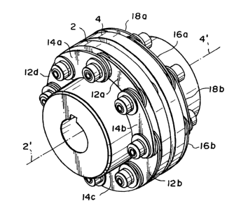
Fig. 1 is an exploded perspective view illustrating a
first embodiment of a shaft coupling according to the present
invention, Fig. 2 is a perspective view of the same in the
assembled condition and Fig. 3 is a partial cross-sectional
view of the same. In these figures, reference numeral 2 denotes
a flange portion at the side of the driving shaft, i.e. driving
side flange portion, which is keyed to an end portion of the
driving shaft (not shown). 2' denotes a rotational axis of
the driving shaft. 4 denotes a flange portion at the side of
the driven shaft, i.e. driven side flange portion, which is
keyed to an end portion of the driven shaft (not shown). 4'
denotes a rotational axis of the driven shaft. The rotational
axis 2' of the driving shaft and the rotational axis 4' of
the driven shaft substantially align with each other. In conse-
quence, the end surface (front surface) of the driving side25 flange portion 2 which faces the driven side flange portion 4
and the end surface (front surface) of the driven side flange
~ortion 4 which faces the driving side flange portion 2 run
in substantially parallel to each other.
Through the driving side flange portion 2, four axially
threaded holes 6a, 6b, 6c, 6d, which are each disposed evenly
', ' ',' `"~,
,~ 212~9~2 :
- 7 -
in the circunlferential direction, and four axial hole portions
7a, 7b, 7c, 7d (not shown) disposed evenly in the circumferen-
tial direction are formed. The positions of these eight threaded
holes or hole portions are allocated evenlY in the circumferen-
tial direction. Similarly, through the driven side flange por-
tion 4, four axially threaded holes 8a, 8b, 8c, 8d disposed
evenly in the circumferential direction and four axial hole
portions 9a, 9b, 9c, 9d disposed evenly in the circumferential
direction are formed. The positions of these eight threaded
holes or hole portions are evenly disposed in the circumferen-
tial direction. Further, four axially threaded holes 6a, 6b,
6c, 6d of the driving side flange portion 2 and four axially
threaded holes 8a, 8b, 8c, 8d of the driven side flange portion
4 are each positioned axially corresponding to each other, and `~
four axial hole portions 7a, 7b, 7c, 7d of the driving side
flange portion 2 and four axial hole portions ga, 9b, 9c, 9d
of the driven side flange portion 4 are each positioned axially
corresponding to each other.
Torque transmitting rods 10a, 10b, lOc, lOd are each
disposed to pass through each of the axial hole portions 7a,
7b, 7c, 7d of the driving side flange portion 2 and each of
the corresponding axial hole portions 9a, 9b, 9c, 9d of the
driven side flange portion 4. Through the foregoing rods,
threaded holes are each formed passing through axiallY-
On a rear surface of the driving side flange portion 2,
eight arcuate driving side leaf spring members 12a, 12b, 12c,
12d, 14a, 14b, 14c, 14d are circumferentially disposed. These
leaf spring members each have a hole at their each end, and
adjacent ones are overlapped at the end portions so that the
holes align with each other. The hole at one end of each leaf
,_, 2l2~982
8 -
spring member is positioned at the position of the driving
side flange portion 2 which corresponds to the axial threaded
hole and, by screwing a bolt into the threaded hole, the leaf
spring member is mounted to the driving side flange portion 2.
Further, the hole of the other end of each leaf member is posi-
tioned at a position corresponding to the rod together with
the hole of the other end of the adjacent leaf spring member,
and 'oy screwing a bolt into the threaded hole of the rod, the
leaf spring member is mounted at the end portion of the driving
side of the rod. As shown, when they are mounted, a washer is
interleaved therebetween.
On a rear surface of the driven side flange portion 4, ;
eight arcuate driven side leaf spring members 16a, 16b, 16c,
16d, 18a, 18b, 18c, 18d are circumferentially disposed. These
driven side leaf spring members are also mounted to the driven
side flange portion 4 and the torque transmitting rod, as in
the driving side leaf spr.ing members. -
Fig. 3 illustrates how each member is mounted in theneighborhood of the rod lOa. As shown, the rod lOa has an outer
diameter smaller than the inner diameter of the hole portions
7a, 9a through which the rod passes, and has a length greater
than the interval between the rear surfaces of the driving
side flange portion 2 and driven side flange portion 4. The
same is also the case with other rods. ~ ~;
The shaft coupling according to this embodiment may be
readily made by assembling the members, as illustrated in Fig.
1. ~
Incidentally, as the leaf spring member, one comprising
a single leaf spring may be used, or ones comprising a plurality
of leaf springs laminated together may be used. Further, depend~
212~982
.
g
ing on the magnitude of the torque to be transmitted, as the
leaf spring member, ones made of a reinforced plastic, which
is favorable for lightening weight, may be used other than one
made of metal.
In this embodiment, when the driving side flange portion - `
2 is rotated, torque is transmitted through the leaf spring
members 12a through 12d, 14a through 14d to the rods lOa through
lOd, from which it is transmitted through the leaf spring mem-
bers 16a through 16d, 18a through 18d to the driven side flange
portion 4.
Based on the deformations such as bend or twist of each
spring member, the following relative movements each becomes
possible between the driving side flange portion 2 and the
driven side flange portion 4 within an appropriate range~
1. rotation around the axial direction;
2. axial movement;
3. movement within a plane intersecting at a right angle
with the axial direction; and
4. rotation which tilts the rotational axis 2' of the
driving shaft relative to the rotational axis 4' of
the driven shaft.
Thus, by suppressing transmission of vibration between
the driving side flange portion 2 and the driven side flange
portion 4, the torque can be smoothly transmitted and, even
if the eccentricity, angular deviation or axial displacement
takes place between the sides of the driving shaft and the
driven shaft, they can be absorbed.
Incidentally, the interval between the driving side flange
portion 2 and the driven side flange portion 4 is set so as not
to prevent the foregoing relative movements between the driving
21289~
.. - 1 o -
. .
side flange portion 2 and the driven side flange portion 4,
which is expected to occur during the operation.
Further, the size of each axial hole portion 7a, 7b, 7c,
, 7d of the driving side flange portion 2 and the size of each
q 5 axial hole portion 9a, 9b, 9c, 9d of the driven side flange
portion 4 are each set with an allowance so as not to prevent
the foregoing relative movements between the driving side flange
portion 2 and the driven side flange portion 4, which is antici- ~;
¦ pated to occur during the operation. In place of the hole por-
10 tion, a notched portion notched outwardly of the flange portion
may also be formed.
In the forgoing embodiment, since only one type of the
leaf spring members 12a through 12d, 14a through 14d, 16a
through 16d, 18a through 18d may be used, the number of types
15 of the components may be small. If either one of the leaf spring
members or the torque transmitting rods is damaged, it is easy
to replace by extracting the bolt at the corresponding part and ~ ~-
the repair is simple. ~ ~
Further, in the foregoing embodiment, since the leaf j ~:
20 spring member is mounted on the rear surface of the driving side
flange portion 2 and the driven side flange portion 4, the axial
dimension can be made smaller for compactness by making the
front surface of the driving side flange portion 2 and the front
surface of the driven side flange portion 4 sufficiently close.
Fig. 4 is an exploded perspective view illustrating a
second embodiment of the shaft coupling according to the present
invention, Fig. 5 is a perspective view of the same which is in
the assembled condition, and Fig. 6 is a partial cross-sectional ;
lateral view of the same. In these figures, 2 denotes a driving
side flange portion, which is mounted with key to the end por-
212~9~2
, ,~
tion of the driving shaft (not shown). 2' denotes a rotationalaxis of the driving shaft. 4 denotes a driven side flange por-
tion, which is mounted with key to the end portion of the driven
shaft (not shown). 4' denotes a rotational axis of the driven
shaft. The rotational axis 2' of the driving shaft and the
rotational axis 4' of the driven shaft are in substantial align-
ment with each other. Therefore, the end surface (front surface)
of the driving side flange portion 2 which faces the driven-
side flange portion 4 and the end surface (front surface) of
the driven side flange portion 4 which faces the driving side
flange portion 2 run in substantially parallel to each other.
At the driving side flange portion 2, two axially threaded
holes 6a, 6b disposed evenly in the circumferential direction
and two axial hole portions 7a, 7b disposed evenly in the cir-
cumferential direction are formed. The positions of these fourthreaded holes or hole portions are evenly allocated in the
circumferential direction. Similarly, the driven side flange
portion 4 is formed with two axially threaded holes 8a, 8b
which are evenly disposed in the circumferential direction and
two axial hole portions 9a, 9b which are evenly disposed in
the circumferential direction. The positions of these threaded
holes and hole portions are evenly allocated in the circumferen-
tial direction. Two axially threaded holes 6a, 6b of the driving
side flange portion 2 and two axial hole portions 9a, 9b of
the driven side flange portion 4 are each positioned in axially
corresponding manner, and, two axial hole portions 7a, 7b of
the driving side flange portion 2 and two axially threaded holes
8a, 8b of the driven side flange portion 4 are each positioned
in axially corresponding manner.
Between the driving side flange portion 2 and the driven
~.`.
212~982
r~
- 12 -
side flange portion 4, a relay member 10 is disposed which
f~nctions to relay the torque transmission from the driving
side flange portion 2 to the driven side flange portion 4. The
relay member is ring-shaped, and two threaded holes 12a, 12b are
each provided at the positions each corresponding to the two
axial hole portions 7a, 7b of the driving side flange portion
2, and threaded holes 13a, 13b are each provided at the posi-
tions each corresponding to the two axial hole portions 9a, 9b
of the foregoing driven side flange portion 4.
Cylindrical spacers 14a, 14b are disposed axially passing
with an allowance through the axial hole portions 7a, 7b of the
driving side flange portion 2. Cylindrical spacers 16a, 16b are
disposed axially passing with an allowance through the axial
hole portions 9a, 9b of the driven side flange portion 4.
On a rear surface of the driving side flange portion 2,
four arcuate driving side leaf spring members 20a, 20b, 22a, 22b
are circumferentially disposed. These leaf spring members each
have a hole at their each end, and adjacent ones are overlapped
at end portions so that the holes align with each other. The
hole of one end of each leaf spring member is disposed at the
position corresponding to the axially threaded hole of the
foregoing driving side flange portion, and by screwing the bolt
into the threaded hole, the leaf spring member is mounted to
the driving side flange portion 2. Further, the hole at the
other end of each leaf spring member is positioned together with
the hole of the other end of the adjacent leaf spring member at
the position corresponding to the cylindrical spacer and, by
screwing the bolt through a hole'of the spacer into the corre-
sponding threaded hole of the relay member 10, the leaf spring
member is mounted to the relay member 10. As illustrated, when
212~982
- 13 -
they are mounted, a washer is interleaved therebetween.
On a rear surface of the driven side flange portion 4,
four arcuate driven side leaf spring members 24a, 24b, 26a, 26b
are disposed circumferentially. These driven side leaf spring
members are also mounted to the driven side flange portion 4
and the relay member 10, as in the driving side leaf spring
member.
The shaft coupling according to this embodiment can readi~
ly be made by assembling the components as shown in Fig. 4.
Incidentally, as the leaf spring member, ones comprising
a single leaf spring may be used, or ones comprising a plurality
of springs laminated together may be used. Further, depending
on the magnitude of the torque to be transmitted, as the leaf
spring member, other than ones made of metal, ones made of a
reinforced plastic, which is favorable for lightening weight,
may also be used.
In this embodiment, when the driving side flange p-ortion
2 is rotated, the torque is transmitted through the leaf spring
members 20a, 20b, 22a, 22b to the relay member 10, from which
it is transmitted through the leaf spring members 24a, 24b, 26a,
26b to the driven side flange portion 4.
Based on the deformation such as bending or torsion of
each spring member, the following relative movements becomes
possible between the driving side flange portion 2 and the
driven side flange portion 4 within an appropriate range:
1. rotation around the axial direction;
2. axial movement;
3. movement in a plane intersecting at a right angle
with the axial direction; and
4. rotation which tilts the rotational axis 2' of the
~ 2128982
- 14 -
driving shaft relative to the rotational axis 4' of
the driven shaft.
Thus, by suppressing the transmission of vibration between
the driving side flange portion 2 and the driven side flange
portion 4, the torque can smoothly be transmitted and, even if
- the eccentricity, angular deviation or axial displacement takes
place between the driving side and the driven side, they can
be absorbed.
Incidentally, the interval between the driving side flange
portion 2 and the driven side flange portion 4 is set so as not
to prevent the foregoing relative movements between the driving
side flange portion 2 and the driven side flange portion 4,
which is expected to occur during the operation.
Further, the size of each axial hole portion 7a, 7b of
the driving side flange portion 2 and the size of each axial
hole portion 9a, 9b of the driven side flange portion 4 are
each set with an allowance so as not to prevent the foregoing
relative movements between the driving side flange portion 2
and the driven side flange portion 4, which is anticipated to
occur during the operation. In place of the hole portion, a
notched portion notched outwardly of the flange portion may be
formed.
In the foregoing embodiment, since the relay member 10
is used, the torsional rigidity can sufficiently be increased.
Further, in the foregoing embodiment, since as the leaf
spring members 20a, 20b, 22a, 22b, 24a, 24b, 26a, 26b ones of
the same configuration may be used, the number of types of
components may be smaller. If one of the leaf spring members
is damaged, it may readily be replaced by letting the bolt at
the corresponding portion off, and the repair is simple.
~"~ ~
"` ~
2~2~982
Further, in the foregoing embodiment, since the leaf
spring member is mounted on the rear surface of the driving side
flange portion 2 and the driven side flange portion 4, the axial
dimension can be made smaller by making the front surface of
the driving side flange portion 2 and the front surface of the
driven side flange portion 4 sufficiently close up to a minimum
distance, and a compaction becomes possible with maintaining
a sufficient flexibility.
Fig. 7 is an exploded perspective view illustrating a
third embodiment of the shaft coupling according to the present
invention, in which like signs are each assigned to the members
or portions having a like function as in Figs. 4 through 6.
In this embodiment, the configurations of the driving side
flange portion 2 and the driven side flange portion 4 differ
from those of the foregoing second embodiment, and lack the
axial hole portions of the flange portion as in the foregoing ~-
embodiment. Further, the relay member lO is formed with mere
holes 12a', 12b', 13a', 13b' instead of the threaded holes.
The bolt passing through these holes fits with the nut. As
illustrated, the angle at which the line interconnecting the
center of the hole 12a' and the center of the hole 12b' forms
relative to the line interconnecting the center of the hole 13a'
and the center of the hole 13b' equals 45 degrees. `~
Also in this embodiment, a similar effect as in the fore~
going second embodiment can be obtained.
Fig. 8 is an exploded perspective view illustrating a
fourth embodiment of the shaft coupling according to the present
invention, and Fig. 9 is a perspective view of the same which
is in the assembled condition. In these figures, like signs are
each assigned to the members or portions having a like functions
- .. . . . ~ ::
:: ~
i ~. ` A ~, ~V~ ~. ~
~ 21~
- 16 -
as in Figs. 4 through 7.
This embodiment differs from the foregoing embodiment in
that the relay member 10 is a maior ring disposed radially
outwardly of the driving side flange portion 2 and the driven
side flange portion 4, and lacks the axial hole portion of the
flange portion as in the foregoing embodiment, and the con-
figuration in which the driving side leaf spring members 20a,
20b, 22a, 22b are arranged and the configuration in which the
driven side leaf spring members 24a, 24b, 26a, 26b are arranged
are each of substantially elliptical form.
Also in this embodiment, a similar effect as in the second
embodiment can be obtained. Further, in this embodiment, since
the relay member 10 is positioned not between the driving side
flange portion 2 and the driven side flange portion, but radial-
ly outwardly, the interval between the driving side flangeportion 2 and the driven side flange portion 4 can be shortened,
and the axial length of the coupling is shortened.
Fig. 10 is an exploded perspective view illustrating a
fifth embodiment of the shaft coupling according to the present ~ ~ ;
invention, and Fig. 11 is a perspective view of the same which
is in the assembled condition. In these figures, like signs are --
each assigned to the members and the portions having a like
function as in Figs. 4 through 9.
In this embodiment, as the driving side spring member 21
and the driven side spring member 25, ones each comprising a
single ring-shaped piece is used. These ring-shaped pieces each
correspond to ones obtained by making the four driving side leaf ~ -
spring members and the four driven side leaf spring members of
the second through fourth embodiments into one. Further, the
relay member 10 has a recess portion lla for receiving the
~ ',~,,
~` , 21~898~
- 17 -
driving side flange portion 2 and a recess portion llb for
receiving the driven side flange portion 4.
Also in this embodiment, a similar effect as in the fore-
going second embodiment can be obtained. Further, in the fifth
embodiment, the number of the components may be small. Further,
since the driving side flange portion 2 and the driven side
flange portion 4 are received within the recess portions lla,
llb of the relay member 10, the interval between the driving
side flange portion 2 and the driven side flange portion 4 can
be shortened with the strength of the relay member held, and
the axial length of -the coupling is shortened.
. ~.
~;
~ '~