Note: Descriptions are shown in the official language in which they were submitted.
21 2~995
MICRO SEGMENTATION IN A HYPERACUITY PRINTER
This application is related to commonly assigned EP Publication No.
0,651,558,A3, published May 3, 1995, titled "Hyperacuity Printer Architecture",
Cross reference is made to the following documents: U.S. Patent No.
5,410,414, titled "Halftoning in a Hyperacuity Printer" EP Publication No.
0,651,559,A3, published May 3, 1995, titled "Two Dimensional Slope
Thresholding in a Hyperacuity Printer" EP Publication No. 0,651,552,A2,
published May 3, 1995, titled "Two Dimensional Linearity and Registration Error
Correction in a Hyperacuity Printer"; and EP Publication No. 0,654,937, published
May 24, 1995, titled "Variable Resolution Processing in a Hyperacuity Printer".
BACKGROUND OF THE INVENTION
This invention relates to an image processing function, and more
particularly, to an image processing function for performing micro segrnent~tion in
a hyperacuity printer.
212899 j
An original document may contain image data having a mixture
of pictorial images and lineart. Photographs and paintings are examples of
pictorial images and are generally halftoned before being printed. The
term "lineart" refers to any information on the original document having a
solid tone of color, for example, an alphanumeric text or a solid color line
and is generally thresholded before printing. This image data can be
electronically scanned in using a raster input scanner or may be generated
by a computer.
A printer can use a halftoning method to achieve many density
levels at the expense of resolution to print pictorials and images or a
thresholding method to achieve two density levels at high resolution to
print alphanumeric text and lineart. In order to print using the halftoning
method and/or thresholding method, the printer has a halftoning circuitry
and/or a thresholding circuitry (hereinafter, respectively, "halftoner" and
"thresholder"). General purpose halftoners and thresholders are known in
the art and thus, need not be discussed in detail.
Although text and lineart can be halftoned to produce a tint of
the desired color, such information is usually printed non-halftoned. A
problem known as aliasing occurs in the printed document when the half-
toning method is used to print the lineart information. The printed
document exhibits jagged edges which degrade the quality of the printed
document. Therefore, if an original document contains pictorial images and
lineart, there is a need for the printer to switch between a halftoning
method for printing the pictorial images and a thresholding method for
printing the lineart. This switching is referred to in the art as segmentation.
For one example, US-A 4,903,143 to Sakamoto discloses an
image processing apparatus having a discriminating circuit for detection an
amount of change in density level of the input pixel data for every pixel and
for discriminating the content of the image of the objective pixel data and
a selector for selecting the processing mode of the projective pixel data in
2 1 28995
accordance with the result of the discrimin~tion. Either halftone processing mode
or the non-halftone processin~ mode is selected by the selector on the basis of the
result of the discrimin~tion. The non-halftone processing mode is continuously
selected from a determined period of time irrespective of the result of the
discrimination.
However, segrnenters of the prior art are only able to switch between
halftoned image date and thresholded image data at pixel boundaries, or within the
resolution of the printing system. This type of segmentation could be referred to as
"macro segmentation." With the advent of microaddressability as discussed in US-A 5,138,339, it has been shown that precise placement of edges beyond the
resolution capability of the printing can be achieved. Therefore, it would be useful
to have a system that could select between halftoning and thresholding, (or evenintermediate functions) using "micro segmentation" within the precision enabled by
that microaddressability when printing edges. For example, if macro segmentationdecisions are made on pixel boundaries, and especially if the pixel data is at arelatively coarse density, then undesirable visible artifacts may be rendered in the
image as the segmenter switches from halftoning to thresholding near an edge.
However, with micro segmentation information available, the edge can be
determined and micro segmentation can be applied with a precision finer than thewriting pitch. It could be possible to use this micro segmentation information to
further enable the output of the thresholder only within a small epsilon distance
from the edge, reducing the opportunity for undesirable artifacts.
SUMMARY OF THE INVENTION
Various aspects of this invention are as follows:
A hyperacuity pnnting system for rentlerin~ image data on a
recording medium, said image data being rendered as an array of pixels across said
-3 -
2 1 28 995
recording medium in a f~t~c~n direction, and an orthogonal slowscan direction,
comprising:
a data source for supplying grayscale input image data;
a sc~nning device for rendering grayscale output image data, said
sc~nnin~ device having a writing device for writing scan spots on said recordingmedium at a writing pitch in said slowscan direction and a writing pitch in saidfastscan direction;
transforrnation cilcuilly for ll~lsrollllil~g said grayscale input image
data into grayscale output image data, said transformation cil~;uilly including a
halftoner, a thresholder, and a selection device, where said selection device selects
either said thresholder or said halftoner to provide said grayscale output image data,
said selection device including a macro selection function and a micro selectionfunction, said micro selection function being able to select said thresholder or said
halftoner with a precision finer than said writing pitch in either said slowscan or
said f~t~c~n direction; and,
a mod~ ting device coupled between said transformation cil~;uilly
and said sc~nning device for intensity mod~ ting each of said scan spots in
accordance with said grayscale output image data.
A hyperacuity printing system for rendering image data on a
photosensitive recording medium, said image data being rendered as an array of
pixels across said photosensitive recording medium in a f~t~c~n direction, and an
orthogonal slowscan direction, comprising:
a data source for supplying grayscale input image data;
a plurality of image processing channels, each channel including:
a sc~nning device for writing grayscale output image data onto said
ecol.lillg medium, said sc~nning device having a writing device for writing scanspots on said recording medium at a writing pitch in said slowscan direction andsaid f~t~c~n direction;
- 2 1 28995
transformation Ch~;Uill~ for transforming said grayscale input image
data into grayscale output image data, said transformation ~;h~uilly including ahalftoner, a thresholder, and a selection device, where said selection device selects
either said thresholder or said halftoner to provide said grayscale output image data,
said selection device including a macro selection function and a micro selectionfunction, said micro selection function being able to select said thresholder or said
halftoner with a precision finer than said writing pitch in either said slowscan or
said f~et~c~n direction; and,
a mod~ ting device coupled between said transformation circuitry
and said sc~nning device for intensity mocllll~ting each of said scan spots in
accordance with said grayscale output image data.
A hyperacuity printing system for rendering image data on a
photosensitive l~cordi~lg medium, said image data being rendered as an array of
pixels across said photosensitive recording medium in a fastscan direction, and an
orthogonal slowscan direction, comprising:
a data source for supplying grayscale input image data;
a sc~nning device for writing grayscale output image data onto said
recording medium, said sc~nning device having a writing device for writing scan
spots on said recording medium at a writing pitch in said slowscan direction and a
writing pitch in said fastscan direction;
transformation circuitry for transforming said grayscale input image
data into grayscale output image data, said transformation ciicuilly including ahalftoner, a thresholder, and a selection device, where said selection device selects
either said thresholder or said halftoner to provide said grayscale output image data,
said selection device including a macro selection function and a micro selectionfunction, said micro selection function able to select said thresholder or said
halftoner with a precision finer than said writing pitch in either said slowscan or
said f~t~c~n direction, said grayscale output image data being composed of
sequences of high
-3b-
- 2128995
and low data values, where a transition between a high data value and a low datavalue defines a boundary written using said grayscale image output data for causing
placement of said boundary with said precision finer than said writing pitch in said
slowscan direction; and,
a mod~ ting device coupled between said transformation circuitry
and said sc~nning device for intensity mod~ ting each of said scan spots in
accordance with said grayscale output image data.
A hyperacuity printing system for rentl~ring image data on a
recording medium, said image data being rendered as an array of pixels across said
recording medium in a fastscan direction, and an orthogonal slowscan direction,
compnsmg:
a data source for supplying grayscale input image data;
a sc~nning device for rendering grayscale output image data, said
sc~nning device having a writing device for writing scan spots on said recordingmedium at a writing pitch in said slowscan direction and a writing pitch in saidfastscan direction;
transformation cir~iuilly for transforming said grayscale input image
data into grayscale output image data, said transformation circuitry including ahalftoner, a thresholder, and a micro segmenter, where said micro segmenter is able
to select between said thresholder and said halftoner with a precision finer than said
writing pitch in either said slowscan or said fastscan direction; and,
a modnl~tin~. device coupled between said transformation cilcuilly
and said sc~nning device for intensity modlll~ting each of said scan spots in
accordance with said grayscale output image data.
In accordance with another aspect of the present invention, provided
is a hyperacuity printing system for rendering image data on a recording medium,the image data being rendered as an array of pixels across the recording medium in
a fastscan direction, and an orthogonal slowscan
-3c-
.. ~
212899~
direction. The system includes: a data source for supplying grayscale input
image data; a scanning device for rendering grayscale output image data,
the scanning device having a writing device for writing scan spots on the
recording medium at a writing pitch in the slowscan direction and a writing
pitch in the fastscan direction; transformation circuitry for transforming
the grayscale input image data into grayscale output image data, the
transformation circuitry including a halftoner, a thresholder, and a micro
segmenter, where the micro segmenter is able to select between the
thresholder and the halftoner with a precision finer than the writing pitch
in either the slowscan or the fastscan direction; and, a modulating device
coupled between the transformation circuitry and the scanning device for
intensity modulating each of the scan spots in accordance with the
grayscale output image data. In addition, the transformation circuitry
could also include a macro segmenter and other image processing functions
which can transform grayscale image input data into grayscale image
output data.
BRIEF DESCRIPTION OF THE DRAWINGS
In the drawings:
Figure 1 is a simplified schematic diagram of a xerographic
printer that is equipped to carry out the present invention;
Figure 2 is a block diagram of a single channel hyperacuity
imager subsystem;
Figure 3 is a diagram of a two channel hyperacuity imager
subsystem;
Figure 4 is a block diagram depicting the elements included in
the FIFO and phase/resolution controller shown in Figures 2 and 3;
212899~
Figure 5 is a block diagram depicting the elements included in
the gray interlace formatter shown in Figure 3;
Figure 6 is a block diagram depicting the elements included in
the resampling interpolator and the phase/resolution controller shown in
Figures 2 and 3;
Figure 7 is a block diagram depicting the elements included in
the y interpolator, x interpolator and slope interpolator shown in Figure 6;
Figure 8 is a diagram depicting the concept of slope thresholding
in two dimensions;
Figure 9 is a block diagram showing the elements of the slope
thresholder;
Figure 10 is a schematic representation of the full creation of a
halftone dot;
Figure 11 is a schematic representation of a step in the creation
of a halftone dot;
Figure 12 is a schematic representation of a step in the creation
of a halftone dot;
Figure 13 is a schematic representation of a step in the creation
of a halftone dot;
Figure 14 is a schematic representation of a step in the creation
of a halftone dot;
21~9~
Figure 15 is a schematic representation of a step in the creation
of a halftone dot;
Figure 16 is a schematic representation of a step in the creation
of a halftone dot;
Figure 17 is a schematic representation of a step in the creation
of a halftone dot;
Figure 18 is a schematic representation of a step in the creation
of a halftone dot;
Figure 19 is a schematic representation of a step in the creation
of a halftone dot;
Figure 20 is a schematic representation of a step in the creation
of a halftone dot;
Figure 21 is a schematic representation of a step in the creation
of a halftone dot;
Figure 22 is a schematic representation of a step in the creation
of a halftone dot;
Figure 23 is a schematic representation of a step in the creation
of a halftone dot;
Figure 24 is a schematic representation of a step in the creation
of a halftone dot;
Figure 25 is a schematic representation of a step in the creation
of a halftone dot;
212899~
Figure 26 is a schematic representation of a step in the creation
of a halftone dot;
Figure 27 is a block diagram of the halftoner;
Figure 28 is a block diagram of the x and y accumulators of the
halftoner in Figure 26;
Figure 29 is a graphical representation of the values loaded into
the x and y accumulators of Figure 27;
Figure 30 is a graphical representation of a halftone dot;
Figure 31 is a graphical representation of a halftone dot;
Figure 32 is a graphical representation of a halftone dot;
Figure 33 is a graphical representation of a halftone dot;
Figure 34 is a block diagram of a variable modulus accumulator
used for addressing the halftoner memory block;
Figure 35 is a block diagram of a modified single channel
hyperacuity imager subsystem including a micro segmenter in accordance
with the present invention;
Figure 36 is a schematic diagram depicting the concept of macro
segmentation on a pixel boundary;
Figure 37 is a schematic diagram depicting the concept of micro
segmentation on a sub pixel boundary;
212899~
Figure 38 is a schematic diagram depicting the concept of
finding the distance to an edge using intensity and two dimensional slope
information;
Figure 39 is a detailed block diagram showing the micro
segmenter of Figure 35 and its relationship to other elements in the
printing system; and
Figure 40 is a detailed block diagram showing another
embodiment of the micro segmenter of Figure 35 and its relationship to
other elements in the printing system.
DETAILED DESCRIPTION OF THE INVENTION
1. SYSTEM OVERVI EW
1.0 Typical ROS System
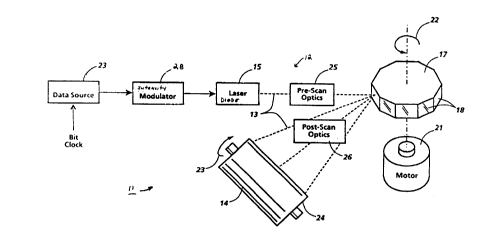
Turning now to the drawings, and at this point especially to Fig.
1, there is a xerographic print engine 11 (shown only in relevant part)
having a more or less conventionally configured flying spot ROS 12 for
scanning a data modulated light beam 13 over a xerographic
photoreceptor 14 in accordance with a predetermined raster scanning
pattern. To that end, the ROS 12 comprises a laser diode 15 for emitting the
light beam 13 in the visible or invisible (e. 9., infrared) band of the
spectrum, together with a polygon scanner 17 that has a plurality of nearly
identical, mirror-like exterior sidewalls or "facets" 18.
In keeping with standard practices, there is a motor 21 for
rotating the scanner 17 about its central axis, as indicated by the arrow 22,
at a substantially constant angular velocity. The scanner 17 is optically
aligned between the laser 15 and the photoreceptor 14, so its rotation
causes the laser beam 13 to be intercepted by and reflected from one after
2128995
another of the scanner facets 18, with the result that the beam 13 is
cyclically swept across the photoreceptor 14 in a fastscan direction. The
photoreceptor 14, on the other hand, is advanced (by means not shown)
simultaneously in an orthogonal, process direction at a substantially
constant linear velocity, as indicated by the arrow 23, so the laser beam 13
scans the photoreceptor 14 in accordance with a raster scan pattern. As
shown, the photoreceptor 14 is coated on a rotating drum 24, but it will be
apparent that it also could be carried by a belt or any other suitable
substrate.
Typically, the ROS 12 additionally includes pre-scan optics 25 and
post-scan optics 26 for bringing the laser beam 13 to a generally circular
focus proximate the photoreceptor 14 and for providing any optical
correction that may be needed to compensate for scanner wobble and
other optical irregularities. Preferably, the optical aperture of the ROS 12
is sufficiently large to avoid excessive truncation of the laser beam 13
because the beam 13 then comes to a generally circular or elliptical focus
with a gaussian intensity profile. However, the broader aspects of this
invention are not limited to any specific scan spot geometry or intensity
profile. Accepted design principles indicate that the spatial frequency
power spectrum of the scan spot profile should not have significant spatial
frequency components outside the spatial frequency passband of the
imaging system, but the scan spot can otherwise be tailored to satisfy a
variety of system requirements.
To carry out the present invention, the amplitude, duty cycle,
and/or pulse width of the laser beam 13 is serially modulated (collectively
referred to herein as its "intensity modulation") by intensity modulator 28
in accordance with successive multi-bit digital data values. These data
values are clocked out of a buffered data source 23 serially in response to
data clock pulses which are time synchronized with the scan of the scan
spot from bitmap location-to-bitmap location within the raster scan
pattern. Thus, the data clock frequency can be selected (by means not
~ 2128995
shown) to map the data onto the raster scan pattern at any desired
resolution, using either the same or different resolutions in the fastscan
and the process directions. As will be appreciated, the data may be
preprocessed (such as by means herein described) for the printing of
halftoned images andtor text and other types of line art, so the data source
23 generically represents any suitable source of gray scale data for intensity
modulating the laser beam 13.
As is known, the fastscan pixel positioning precision of the print
engine 11 can be enhanced, if desired, by dynamically adjusting the
frequency of the data clock to compensate for the pixel positioning errors
that tend to be caused by "motor hunt" (i. e., variations in the angular
velocity of the scanner 17), "polygon signature" characteristics (variations
in the angular velocities at which the different facets 18 of the scanner 17
sweep the scan spot across the photoreceptor 14 from a start of scan
position to an end of scan position), and "scan non-linearities" (i. e.,
localized variations in the linear velocity of the fastscan, which are caused
by variances in the geometric relationship of the scanner 17 to spatially
distinct segments of any given scanline). For more information on these
sources of potential pixel positioning errors and the compensation that can
be provided for those erro-s, the following commonly assigned United
States Patents are referred to D.N. Curry US-A 4,622,593 which issued Nov.ll, 1986
on "Polygon Signature Correction"; D. N. Curry US-A 4,639,789 which issued Jan.
27, 1987 on "Raster Scanner Variable-Frequency Clock Circuit"; D. N. Curry et al.
US-A 4,766,560 which issued Aug. 23, 1988 on "Parallel/Pipelined Arithmetic
Variable Clock Frequency Synthesizer"; D. N. Curry US-A 4,860,237 which issued
Aug. 22, 1989 on "Scan Linearity Correction"; D. N. Curry US-A 4,893,136 which
issued Jan. 9, 1990 on "Arithmetically computed Motor Hunt Compensation for
Flying Spot Scanners"; and D. N. Curry US-A 4,935,891 which issued Jun. 19, 1990on "Pseudo-Random Phase Shifted Arithmetic Bit Clock Generators for Digital
Printers."
21 28995
It is to be understood, however, that the increased pixel
positioning precision of the existing compensation techniques listed above,
strictly pertain to the spatial positioning of the pixel centers in the fastscandirection. Thus timing is used to adjust the fastscan pixel positions. This
differs from the two dimensional "high addressability" or
"microaddressability" utilized herein because microaddressability enables
image transitions to be spatially positioned with subresolution precision in
both the process direction and the fastscan direction. This feature
sometimes is referred to as "two dimensional high addressabilityn or, in
abbreviated form, as "2D high addressability" and is fully described in
commonly assigned United States Patent US-A 5,138,339 to D.N. Curry et al.,
which issued Aug. 11, 1992 on Microaddressability Via Overscanned
Illumination For Optical Printers And The Like Having High Gamma
Photosensitive Recording Media". Typically, Intensity is used to adjust the pixel
positions in the process direction.
In particular, according to US-A S,138,339 which can be utilized
by the present invention, the pitch of the scan pattern for the printer 11 is
selected to be significantly finer (i. e., smaller) than the FWHM (full width
half max) diameter of the scan spot that is formed from the scan beam 13.
This relatively fine pitch scan pattern causes the printer 11 to operate in an
"overscanned" mode because the FWHM central core of the scan spot
sweeps across spatially overlapping segments of the photoreceptor 14
during the scanning of spatially adjacent (i. e., neighboring) scanlines.
Overscanning slightly degrades the spatial frequency response of the
printer 11 in the process direction. However, it has been found that the
linearity of the addressability response of ROS printers, such as the printer
11, increases rapidly as the ratio of the scan pitch to the FWHM diameter of
the scan spot is reduced to progressively smaller, sub-unity values (i. e.,
increasing the overscan). In other words, it has been found that
overscanning is the key to providing the essentially linear position control
that enables discrete exposures to map image transitions onto a scan
2l2899~
pattern at a subresolution precision. Thus, in the printer shown in Fig. 1, a
relatively small loss of process direction frequency response is accepted to
achieve substantially increased process direction addressability. The use of
an overscan factor (i. e., the ratio of the FWHM diameter of the scan spot to
the scan pitch) in excess of about 2x only marginally improves the linearity
of the addressability response of the printer 11, so designers contemplating
the use of overscan factors greater than 2x or so should carefully analyze
the overall performance of the system that is being designed to ensure that
it is satisfactory.
The reason that it is important to adjust the pixel positions with
subpixel or subscan precision in both the fastscan and process directions is
because of the ability of the human visual system to perceive edge
placement precision from 10 to 60 times more precisely than the acuity
(resolution) of the visual system. This ability of the human visual system is
referred to as hyperacuity. Thus, the resolving power of the printer need
extend just beyond the visual system's acuity cutoff of around 300 to 400
lines per inch at a twelve inch view distance, the hyperacuity response of
the printer needs to be able to position the edges of these relatively coarse
marks with a precision of from 3,000 to 20,000 positions per inch. It is not
practical to implement high speed printers with resolutions of 3,000 to
20,000 pixels per inch, so the alternative is to make a scanner with similar
characteristics as the human visual system: its hyperacuity response is an
order of magnitude or more greater than its own resolution. The linearity
provided by overscanning enables this performance.
It then becomes necessary to provide this scanner with enough
fidelity information to drive it. Bitmaps, which are usually used, are a poor
source, because they do not efficiently store hyperacuity information. The
information is best provided by gray source data, which can have a limited
resolution of 300 to 400 samples per inch, for instance, and a gray depth of
perhaps 8 bits, which is logarithmically encoded to achieve 256 levels, which
provides the hyperacuity information. This data can be converted in real
2128995
time with the electronics herein described to produce the high bandwidth
gray data destined for the photoreceptor or media. Thus, this information,
which amounts to the equivalent of over 23 million bits per square inch (at
4800 x 4800 addressability units per inch, for instance), is used only on the
photoreceptor or media, not stored in an expensive page buffer.
2.0 Hyperacuity Printer Architecture
High quality printing not only depends on machine noise and
exposure quality, but on how much fidelity information can be passed on to
the printer from the data source. It is the purpose of the electronics in the
printer to convert high fidelity, sampled representation into a high
bandwidth, high resolution bit stream for delivery to the photoreceptor.
Figure 2 shows a block diagram of the subsystem components in a
hyperacuity printing system, referred to herein as printer S0. Printer 50 can
be implemented like the xerographic print engine 11 of Figure 1, however,
it is not intended to be limited to such a print engine configuration.
Printer 50 includes data sources from Image Generator 51
including Grayscale Image Generator 52, Binary Image Generator 54, and
Grayscale Converter 56. Further included are FIFO (First In First Out)
memory 58, Resampling Interpolator 60, segmenter 6Z, Phase/Resolution
Controller 66, halftoner 70, D to A converter 76, laser diode 15, and
Linearity and Registration Controller 78. The resampling interpolator 60,
halftoner 70, thresholder 68 and digital to analog converter 76 are
responsible for the conversion of the sampled representation into a high
bandwidth, high resolution bitstream for delivery to the photoreceptor via
laser diode 15.
Figure 3 is a block diagram of a two channel hyperacuity printer
whereby the printer has two laser diodes. Note that the system of Figure 3
includes the same elements as the system shown in Figure 2, with the
addition of interlace formatter 80. Printer 50 will be generally described
-13-
21 28995
below, with detailed descriptions of each subsystem component following
the general description.
The image generator used in the printing system can be binary
or gray, and is not restricted to a specific resolution or gray (multi-bit)
depth. In general, gray depth over an image can be variable to
accommodate a physical interface with the imager subsystem or to adjust
the fidelity of image information sent to the printer, while sample density
(the number of samples per inch) will be adjustable up to some maximum
to match the resolution goal of the imager. As shown in Figure 2, image
data may be provided by grayscale image generator 52 which provides
multiple bit per pixel data to FIFO 58. Or, image data may be provided in
binary format, (i.e. one bit per pixel), by binary image generator 54. This
binary data from generator 54 can then be converted to grayscale by
grayscale convertor 56 before processing. A typical operation performed
by the grayscale convertor 56 is convolution or filtering, then scaling of a
high resolution binary image into a coarser gray image. However, the edge
information present in the binary image is encoded naturally by the
convolution or filtering operation into gray depth. An exemplary
description of a grayscale convertor can be found in commonly assigned, U.S. Patent
Number 5,479,584 titled "Enhanced Fidelity Reproduction of Images With Device
Independent Numerical Sample Output" corresponding to EP Publication No.
0.585,043,A3, published March 2, 1994.
The image generator 51 also can download (in advance of
printing) halftoning and thresholding information tuned to the special
characteristics of the imager and the desired imaging response. This
download file is not image data, but rather the contents of the look-up
table used for halftoning or thresholding. For example, software in the
image generator could determine the level to erode or dilate a specified
font for the target write black or write white platform, and produce an
appropriate download file.
-14-
, 212899~
FIFO 58 provides buffering which allows data to be delayed for
use in multi diode configurations and delayed for accessing two adjacent
scans for interpolation. As will be seen, in a multi-diode configuration, the
diodes are positioned along the process direction with some beam spacing
distance. Because of this, at any moment during printing, one diode will be
accessing data from a different portion of memory in the process direction
than another diode. Control of the FIFO buffers in a multi-channel
configuration, such as that of Figure 3, is the responsibility of interlace
formatter 80 in cooperation with phase/resolution controller 66. Since the
image information is sent only once from the image generator in the form
of serial rasters, the FIFO buffers the number of rasters spanned by the laser
diodes in the process direction. Furthermore, FIFO 58 provides delayed
raster information for use with other image processing functions. In this
case, these delayed rasters are used by resampling interpolator 60 in pairs.
The existence of resampling interpolator 60 in the electronic
pathway between the image generators and the output allows a unique
opportunity to electronically map data spatial position into arbitrary
misalignment of the imager and its mechanical process as well as the
customary use which provides resolution conversion. The information
required to conformally map the data into the imperfections of the engine
and laser scanner are obtained from the linearity and registration
controller 78, and processed through phase/resolution controller 66, and
can be viewed as a dynamic resolution control. Any imperfection in the
platform which can be measured accurately can be servoed electronically
for conformal electronic registration.
Resampling interpolator 60 executes a standard image
processing function of interpolation, which can be linear interpolation for
processing simplicity. For the hyperacuity printer 50, the spot on the
photoreceptor is tracked by appropriate electronics, taking into account
electronic registration requirements. Without electronic registration
feedback, the phase/resolution controller 66 would start from zero and
2~ 28995
accumulate a constant value in both the fastscan and slowscan directions.
With feedback, however, the start values or accumuland values are
dynamically biased by adding in changing error values during printing. This
information about the spot's current position is passed to resampling
interpolator 60 which returns a sample intensity for that position, called a
resample.
To obtain a resample, the spot's current position, measured in
units of addressability in both x (fastscan) and y (slowscan or process)
dimensions, is not necessarily coincident with one of the integer sample
positions, but instead fractionally positioned among four of the nearest
neighbors. The interpolator executes an algorithm which estimates what
the sample intensity is at the current position by extrapolating the
intensities of these four closest neighbors. The simplest form of this
calculation assumes that the intensity varies in a straight line between
adjacent samples, thus the term linear interpolation.
In addition, the resampling interpolator 60 will simultaneously
calculate the local rate of change (slope) of the intensities and pass this
information on to thresholder 68 as shown by line 85. This information can
be used to predict where the exposure intensities of lineart will cross the
xerographic threshold.
As mentioned above, the resampling interpolator is used for resolution
conversion. Commonly assigned, U.S. Patent Number 5,357,273 titled "Resolution
Conversion Via Intensity Controlled Overscanned Tllumin~tion for Optical Printers
and the Like Having High Gamma Photosensitive Recording Media" corresponding
to EP Publication No. 0,580,388,A1, published January 20, 1994 describes an
alternative means and method of pel~-,--iilg resolution conversion in the process
direction in a hyperacuity printer, without the use of a resarnpling interpolator.
Commonly assigned US-A Patent No. 5,220,760 titled, "Arithmetic Technique for
Variable Resolution Printing in a ROS," and
-1 6-
2 1 23995
cornmonly assigned U.S. Patent No. 5, 382,967 titled, "Continuously Tunable Raster
Resolution Printing" corresponding to Japanese Laid-Open Patent Application
Number 4-233367 laid -open August 21, 1992 also address resolution conversion inthe process direction, but do not use an interpolator.
Thresholder 68 converts the resampled information from
interpolator 60 into a gray data stream which drives the D to A converter
when lineart, such as fonts and lines, is to be rendered. The hyperacuity
printer 50 has the ability to position edges of image regions very precisely
in the process and fastscan directions due to the use of timing and variable
intensity as described above. The thresholder, however, attempts to render
the sampled data by estimating where the sampled representation crosses
the xerographic threshold. One form of hardware to accomplish the
thresholding function is a cache memory acting as a look-up table. Another
form of hardware to perform the thresholding function could be a
processor or other suitable electronics to calculate the function in real time.
The thresholder 68 utilizes two dimensional slope information,
line 85, generated by resampling interpolator 60, (which is generally
thrown away in conventional interpolation schemes), and therefore is able
to predict threshold crossings of the input file with subpixel precision. This
is important because it means that using bitmaps with ever increasing
resolution (beyond the human visual systems' acuity cutoff of around 300
to 400 pixels per inch at a 12 inch view distance, for instance) to position
edges is no longer necessary.
In addition, this edge information can be used in conjunction
with prior knowledge of the printer tone reproduction curve (TRC) and spot
dimensions to compensate for the width of the spot, and thus achieve
printer device independence for rendering an image on charge area
development (write-black) printers or exposed area development (write-
white) printers. This also makes the need to predistort fonts to compensate
for printing on particular printers unnecessary.
212893~
Halftoner 70, including dot generator 72 and screen generator
74, converts the resampled information from resampling interpolator 60
into a binary map when pictorials are to be rendered. Pictorials require
many levels of gray to be contour free, as well as a fine dot structure to
make graininess imperceptible. A 4800 per inch addressability printer (1200
scans per inch and 4 levels of gray on photoreceptor, for instance) will have
the ability to produce bitmaps with over a thousand levels of gray at 150
halftone dots per inch, for example (4800 / 150 = 32 addressability units per
halftone cell side; 32 x 32 = 1024 possible levels). In addition, the tone
reproduction curve can be embedded into the dot definition since only 256
levels (or less) need to be represented in the input data. In addition, the
laser spot shape and size is compensated for. In order to accomplish this, a
high fidelity representation of a halftone dot is required.
The definition for the halftone dot, as a function of spot position
on the photoreceptor and the required gray level is stored in a memory. As
the spot scans, the intensity of the spot will be adjusted by the D to A
converter (or any other intensity modulation scheme such as pulse width
modulation or duty cycle modulation, for instance) by the multi-bit (gray)
output of the halftoner to define the boundaries of the halftone dots. For
the case of a halftone dot with a pitch of 1/150 inch, 4800 addressability
(4800 / 150 = 32 addressability units on each side of the halftone cell) and
256 different gray levels, the number of bits required in memory to define
it is on the order of a million (32 x 32 x 256 memory locations x 4 bits per
memory location = 1.05 million bits in the memory of the example.).
This halftoner differs with others of prior art in that intensity
information (256 values) as well as screen position (32 x 32 values) are used
as an address into the memory, and the multi-bit value output is directed to
a gray modulator. Prior art halftoners retrieve a value based on the screen
address only, compare it with the input intensity information (with a
-18-
2128995
hardware comparator), and turn a laser either on or off depending on
whether the value retrieved is above or below the input intensity.
In addition, halftoner 70 has very fine control over the halftone
dot shape and size. For example, the halftoner will be able to produce dots
with elliptical shape, or other optimized shapes to minimize dot gain in the
mid tones or maximize impulse response in the highlight areas.
In order to properly render printed images, all display systems
utilizing binary presentation, such as xerography and offset lithography,
must be able to discern the difference between gray images (toneart or
pictorials), and synthetic images (lineart, including text and lines). This is
because binary printers must print gray images by halftoning. There is no
ability to control a sufficient gradient of gray to produce continuous tone,
as in photographs or thermal transfer printers. On the other hand, it is
important from a visual point of view that high contrast lineart and text be
printed with smooth edges. This is accomplished through segmentation via
segmenter 62.
When printing the sampled representations, the samples will be
passed through both halftoner 70 (for toneart) and thresholder 68 (for
lineart) simultaneously. An additional bit, known as a segmentation bit or
tag bit, line 63 from FIFO 58, is carried along with the multi-bit sample
pixel and is delivered by the segmenter 62, after suitable time delay to the
halftoner and thresholder. This bit will be used to switch between these
two devices during printing, according to whether toneart from the
halftoner or lineart from the thresholder is to be rendered. The resolution
of information which determines this can be as high as one bit per sample,
or some lower number. In order to control from where D to A converter 76
gets its input, segmenter 62 can either modify the input addresses to
halftoner 70 and thresholder 68, or provide an enable signal to tri-state
output devices on the outputs of halftoner 70 and thresholder 68. In any
19-
2 1 28q95
case, segmenter 62 provides a switching function between thresholder 68
and halftoner 70 via output 64.
Commonly assigned Japanese Laid-Open Patent Application
6-133,161 laid-open May 13, 1994 titled "Edge Segmentation in a Two-
Dimensional High Addressability Printer," also describes a segmentation
implementation for use with a hyperacuity printer as described herein. The
segmenter of 6-133,161 ùtilizes slope information 85 from resampling
interpolator 60 in det~ninin~ segmentation.
It can be appreciated that other segmentation algorithms
known in the art, including real-time segmentation analysis, may be used to
differentiate between pixels to be halftoned and pixels to be thresholded.
In addition, more than two segmentation partitions may be utilized by
adding new algorithm hardware in parallel, and switching among them
with extra segmentation or tag bits.
So far, the segmentation functions described perform a type of
"macro segmentation" whereby the segmentation function can be applied
on a pixel-by-pixel basis, or at a precision which is equal to the resolution ofthe system. However, as will be seen with reference to Figures 35-40, an
additional segmentation element can be included in printing system 50,
whereby the additional segmentation element performs a "micro
segmentation" function. With micro segmentation, the segmentation
function can be applied with a precision finer than the resolution of the
system.
Continuing with the description of system 50 as shown in Figures
2 and 3, halftoner 70 and thresholder 68 provide several intensity levels at
the frequency specified by the fastscan clock. The number of levels is
determined by system design considerations, including tradeoffs between
clock rate, number of channels, machine throughput, and xerographic
-20-
2 1 28995
noise. D to A converter 76 can use duty cycle, pulse width or current control
to achieve the analog conversion for several light intensities.
Note that, because of the way in which levels are specified, the
number of values required to encode the levels is always one more than
number of levels. For instance, if four levels are specified, the required
values for intensity would be 0%, 25%, 50%, 75%, 100% = 5 values. It can
be appreciated that more than four levels, such as 16 or 256, could be useful
and easy to implement.
An important aspect of a hyperacuity printer is the incorporation
of laser diode source 15. The laser diode 15 offers a bandwidth well into
the GHz range, with the ability to modulate its intensity with electronic
current control. In addition, laser diode may be produced in a monolithic,
closely-spaced multi-beam configuratfon, allowing throughput and quality
improvements. In the configuration shown in Figure 3, a two laser diode
system is illustrated. Commonly assigned US-A Patent No. 5,216,443, titled
"Programmable Intensity Smart Laser System Capable of Being Fabricated
on a Semiconductive Substrate" discusses embedding the digital to analog (D to A)
conversion on the semiconductor substrate with the laser diode, the D to A
conversion being controlled using pulse width modulation.
Another useful and unique feature available in printer 50 is that
of linearity and registration control. For instance, color reproduction
demands a greater precision in machine mechanical requirements for
registration to achieve color layer to layer registration in the one to two mil
range. It is extremely important that layer to layer registration be
precise. With such precision, it can be possible to achieve process color for
lines and text using this system. This precision is extremely difficult and
expensive to achieve mechanically. Other requirements for registration in a
multi station color machine can also be met, where each writing station
would be calibrated to deliver a pixel map which overlaps precisely the
.~
212899~
pixel maps of the others. It is evident that, assuming the errors can be
measured, that the two dimensional hyperacuity printer will be able to
achieve these goals through electronic registration using linearity and
registration controller 78. For example, at 4800 per inch addressability, the
placement precision of edges is .2 mils.
Linearity and registration controller 78 does this by feeding back
spot position error information to phase/resolution controller via line 81.
Controller 78 also appropriately displaced samples to the decomposer
electronics (halftoner 70) via line 83. In addition, x-y position registration,
scan linearity correction, velocity servoing and photoreceptor skew and
runout correction can be performed electronically while relaxing the
specifications on the optomechanical components.
Turning now to Figure 4 through Figure 3x, each subsystem in
printer 50 will be described in detail.
Il. SYSTEM DETAILS
1.0 FIFO
Figure 4 is a detailed block diagram of the elements included in
FIFO 58 and phase/resolution controller 66. FIFO 58 is a memory device
configured to be utilized as a two dimensional (2-D) window on the image
data stored therein, having a fastscan (x) and a slowscan (y) dimension.
Phase/resolution controller 66 as well as interlace formatter 80 will assist in
providing addresses into that 2-D window
FIFO 58 has memory 82 in which a number of rasters, or scanlines
are stored. Each raster has a plurality of pixels, and each pixel has one to
eight bits. The width of memory 82 is at least large enough to store an
entire raster of pixels. In addition, the width includes capacity for the
segmentation or tag bit or bits, as necessary. Segmentation or tag bits are
2128995
delivered to the segmenter through line 63, and are stored with the pixel in
the FIFO to insure correct time delay in application of the halftoning or
thresholding algorithms. The height of memory 82 is at least large enough
to compensate for the beam spacing in a multi-channel system, plus
accommodation for one raster to be used by resampling interpolator 60,
and plus one or two rasters to enable the reading of one raster while
writing another. Typically four to eight rasters are stored, but the invention
is not limited by such.
FIFO 58 is configured such that it is a three port memory having
one write port and two read ports. As memory 82 is being addressed,
simultaneously the image generator loads the raster being generated into
the FIFO as two rasters are being read out for processing. As will become
apparent, the x address for all three ports are the same while the effective y
address for each port is different by a given offset. Furthermore, for a
given x address, the pixel stored at that address for each raster stored in
memory 82 is available.
Memory 82 is addressed in the x direction by XADDR
demultiplexer 84 (demux). Phase/resolution controller 66 supplies a
fourteen bit number via XADDRESS line 111 to demux 84 thereby allowing
demux 84 to address 214 pixels along a raster stored in memory 82.
Phase/resolution controller 66 supplies a four bit number via YADDRESS line
99 creating 24 addresses. In the y direction there need to be offsets in the
addressing in order to accommodate simultaneous reading and writing of
memory 82. in order to create the necessary offsets for y direction
addressing, full adder 92 adds a fixed value to YADDRESS 99 which in turn is
used by YADDR demux 86 for write port addressing. In a similar manner,
full adder 94 supplies a fixed offset to one of the two read ports. Since all
rasters stored in memory 82 are available simultaneously, mux 88 and mux
90 are used to select two of the rasters for processing at any one time. It is
the use of these two muxes that creates the two read ports. Data from mux
88 is shown as line LAST 89 while data through mux 90 is shown as NEXT
212899~
line 91. The use of the LAST and NEXT rasters will become apparent when
discussing the resampling interpolator. Note that the addresses do not
advance by more than one at a time, thus the FlFO-like nature of this
memory subsystem.
2.0 Phase/Resolution Controller
One purpose of phase/resolution controller 66 is to provide
addressing to FIFO 58 as described above. Another purpose of phase
resolution controller 66 is to provide a fractional accumulated number for
use by resampling interpolator 60.
Phase/resolution controller 66 has a y accumulator 96 and an x
accumulator 108. Y accumulator 96 includes register 98 and full adder 100.
Register 98 is a sixteen bit register whereby the leftmost four bits represent
the integer portion and the remaining twelve bits represent the fractional
portion of the sixteen bit number. The integer portion is used as the
YADDRESS line 99 while the fractional portion is multiplication factor line
YFRACT 101. As will be seen, YFRACT 101 will be used by resampling
interpolator 60.
Phase/resolution controller 66 also has X accumulator 108. X
accumulator 108 includes register 110 and a full adder 112. Register 110 is a
twenty-four bit register whereby the leftmost fourteen bits represent the
integer portion and the remaining ten bits represent the fractional portion
of the twenty-four bit number. The integer portion is used as the
XADDRESS line 111 while the fractional portion is multiplication factor line
XFRACT 113. As will be seen, XFRACT 113 will also be used by resampling
interpolator 60.
Each accumulator has associated with it a loadable INC register
and a loadable START PHASE register. During each clock cycle controlling
the accumulators, the accumulators can only increment by the number
-24-
212899S
loaded in the INC registers. The value loaded in the INC registers is
fractional, therefore the accumulation is fractional. As will be understood
from the discussion of the resampling interpolator, the fractional
increment enables the calculation of pixels values between two pixels
and/or two rasters stored in the FIFO. Once the accumulators have
accumulated the fractional value whereby it rolls over into the integer
value, the address into the FIFO is at the next address position, or pointing
to the next pixel or raster of data. In the system described herein, in order
to satisfy Nyquist criteria, it may be desirable to have at least two clock
cycles before changing to the next address, therefore the INC values may be
restricted to less than or equal to 0.5.
For x accumulator 108, the value in INC register 114 is equal to
the number of samples per inch in the fastscan direction, divided by the
number of fastscan clocks per inch. For instance, at 600 samples per inch,
and 4800 fast scan clocks per inch, INC=0.125. The value in START PHASE
register 116 equals zero, (unless a registration correction value has been
provided by the linearity and registration controller 78, which will be
discussed later). The process for determining the values in the INC register
102 and START PHASE register 104 for y accumulator 96 will be explained in
more detail with reference to the interlace formatter.
At the beginning of a page, register 98 of y accumulator 96 is
loaded with a START PHASE value from register 104. With each start of scan
clock signal, SOSCLK, y accumulator 96 is incremented by the value stored in
INC register 102. Since the number being accumulated is fractional, the
integer part of the number in register 98 will not be incremented by more
than one at a time. In this example, registers 102, 104 are each thirteen
bits.
At the beginning of a scan, register 110 of x accumulator 108 is
loaded with START PHASE value from register 116. With each system clock
signal, SYSCLK, x accumulator 108 is incremented by the value stored in INC
2128~9~
register 114. Since the number being accumulated is fractional, the integer
part of the number in register 110 will not be incremented by more than
one at a time. In this example, registers 114, 116 are each eleven bits.
In general, the x and y address for the FIFO are tracked by the x
accumulator for the fastscan direction and with the y accumulator for the
slowscan direction. Therefore, the integer portions of the accumulators
should never advance by more than one since the system is systematically
clocking through the memory in a FlFO-like fashion.
3.0 Interlace Formatter
The phase/resolution controller along with the interlace
formatter facilitate resolution conversion, registration correction, and
interlacing. Referring to Figure 5, the interlace formatter is basically a
duplication of the y components in the phase/resolution controller with an
offset to allow each channel to access the FIFO raster data at a point in the
data which matches the channel's beam position in the two channel system
of this example. The offset loaded into the START PHASE registers,
accounts for the beam spacing between photodiodes. As shown, there is a
connection (line 99) between the channels, which maintain the write
address for both channels, thus causing the write address for both channels
to be the same. Since the write address is the same, the same data is being
written into the memory of each channel simultaneously. However, due to
the values in the START PHASE registers, the read address is staggered to
compensate for the distance between the two photodiodes. Therefore, the
the image generator only needs to write one raster at a time into memory
before printing, thereby decreasing its complexity over prior systems which
required the image generator to supply different data to each channel
simultaneously. The interlace formatter facilitates accessing data in the
memory in two places simultaneously, thus creating interlacing
automatically. The interlace formatter described herein has the the ability
to map any interlace factor into any set of rasters that are in the memory.
-Z6-
2 1 28995
..
Comrnonly assigned, US-A Patent No. 5,233,367 titled "Multiple Beam
Interlace Sc~nnin~ System" describes an image forming apparatus and method for
interlace sc~nning plural light beams by deflecting the plural beams with a rotating
polygon onto a recording medium wherein the spacing between adjacent beams hold
the relation
B~of
Q V
wherein I is an interlace factor equal to the number of reference scans
between adjacent beams from a single facet of the polygon on the
photoreceptor. The photoreceptor velocity is VO, ~u is the polygon angular
velocity, f is a number of facets per revolution of the polygon, Q is the
number of beams and B is the beam spacing. As will be shown, the
interlace formatter described herein implements a hardware configuration
which utilizes the above equation to facilitate interlacing by mapping
rasters into the polygon scan structure of the system.
Generally, for interlace scanning, any positive value for the
interlace factor I may be selected. By selecting various values for the
interlace factor I and the number of beams Q, it is possible to obtain equally
spaced, fractional or multiple interlace scanning.
For equally spaced, non-overlapped interlace scanning, I must be
selected as a positive integer and itself and Q must not have any common
integer divisors greater than 1. For equally spaced, non-overlapped,
interlace scanning, the interlace factor I is the distance between adjacent
scans laid down by a single facet of the polygon divided by the distance
between adjacent, interlaced scans. Between any two adjacent scans laid
down by a single facet of the polygon are interlaced additional scans laid
down by prior or subsequent facets of the polygon.
2128~95
In a dual channel interlace formatter shown in Figure 5, there is
a master channel (channel 0) and a slave channel (channel 1). For clarity,
the device numbers in the slave channel are indicated with a prime
notation. The values for START PHASE registers can be calculated by the
equation START PHASE = (ch)(D)(B) where ch is the channel number, D is the
target data density, or data resolution, in rasters per inch, on the
photoreceptor and B is the beam spacing, in inches, between the
photodiodes. B can be found from the equation above or can be measured.
In Figure 5, START PHASE register 104 is loaded with a zero, since it is in
channel zero. START PHASE register 104' is loaded with (D)(B) since it is
channel 1. This is the amount of offset into the memory required for
i nterlaci ng .
The value in the INC registers 102, 102' represents how many
rasters the photoreceptor moves per single facet. INC equals the density
(rasters/inch) times Vo/wf in inches/facet. In other words, INC represents
how far it is necessary to go through the FIFO by a certain number of
rasters. This number can be fractional.
Since INC can be fractional, y accumulators 96, 96' can request
pixel values for a scan which falls between rasters. Therefore, y
interpolators are used to interpolate the necessary data. A significant
feature of this interlace formatter is in its ability to look into the FIFO, getthe two rasters needed depending on where the scan is on the
photoreceptor, and interpolate therebetween in order to get the correct
data within a fraction of a raster precision.
4.0 Resampling Interpolator with slope output
Figure 6 and Figure 7 are detailed block diagrams of resampling
interpolator 60 and associated circuitry. The outputs of the resampling
interpolator are used for several image processing functions in the
hyperacuity printer. First, sampled pictorial data can be reconstructed for
2128995
use by the halftoner. Second, sampled text and lineart data can be
reconstructed with an enhancement to the operation of the interpolator by
retaining local slope information (rate of change of intensities), thereby
enabling the prediction of where the sampled image will cross the
xerographic threshold. The slope information will be used by the
thresholder. Third, the interpolator may be used to resample the input
data at different rates to achieve different resolutions, magnification
and/or angular orientations of the input data. The resampling interpolator
of this system is designed such that the target density or resolution can be
written independent of the input resolution of the data in the memory.
Finally, electronic registration, scan linearity correction, velocity servoing
and photoreceptor skew correction can be performed in the printing
system through suitable measurement and feedback of the errors in spot
position. This information will be provided by the linearity and registration
controller.
Referring to Figure 6, resampling interpolator 60 receives two
lines of adjacent raster data, appropriately labeled NEXT 91 and LAST 89,
from the FIFO. The raster data is first processed by y interpolator 120 and
then passed on to x interpolator 122 via data line 126. At the same time the
raster data is being processed, slope information is being supplied by y
interpolator 120 and x interpolator 122. Y slope information is processed
by slope interpolator 124. Details of each interpolator will be discussed
with reference to Figure 8. As part of the processing of both the raster data
and the slope data, y interpolator 120 uses the fractional part of the
number, YFRACT 101, from y accumulator 96. In a similar manner, x
interpolator 122 and slope interpolator 124 both use the fractional part of
the nùmber, XFRACT 113, form the x accumulator 108. The outputs of
resampling interpolator 60 include interpolated raster data,
INTERPYINTERPX 128, with associated slope information, SLOPEX 132 and
interpolated slope data SLOPEYINTERPX 134.
-29-
2128995
Referring now to Figure 7, shown are detailed block diagrams of
y interpolator 120, x interpolator 122 and slope interpolator 124. Raster
data from the FIFO in the form of NEXT line 91 and LAST line 89 are
supplied to y interpolator 120. These two rasters represent adjacent raster
from an image stored in the FIFO. As shown, raster LAST 89 is subtracted
from raster NEXT 91 using full adder 136. Subtraction is accomplished
through twos complement arithmetic whereby bubble 137, on the B input
of adder 136, denotes an inverse function and a + 1 on the CIN input adds
the plus one necessary to carry out the twos complement function. The
result of this subtraction is then multiplied by YFRACT 101 which is the
fractional part of the number stored in y accumulator 96 (Figure 6). Also as
a result of this subtraction is the associated y slope information shown as
SLOPEY line 130. Multiplier 138 performs an 8x8 multiplication in which
the eight most significant bits of the result, line 139, are passed on to full
adder 140. Full adder 140 adds the result of the multiply with raster LAST
89 to complete the y interpolation, with the result being line INTERPY 126.
INTERPY 126 represents the y interpolated data.
X interpolator 122 receives its input from the output of y
interpolator 120. Line INTERPY 126 becomes the A input to full adder 142.
Also, line INTERPY 127 is delayed one pixel by register 141. The result of
this delay, LAST INTERPY, is inverted by bubble 143 and then input into the
B input of adder 143 with the carry input held high. Therefore, using twos
complement arithmetic, LAST INTERPY is subtracted from INTERPY. The
result of this subtraction produces associated x slope information SLOPEX
132. Also, the result of the subtraction becomes an input to multiplier 144.
Multiplier 144 multiplies XFRACT 113, which is from the fractional part of
the number in the x accumulator 108 (Figure 6), by the output of adder 14Z.
The most significant eight bits of the result of the multiplication is then
added to LAST INTERPY by adder 146, resulting in interpolated data
INTERPYINTERPX 128.
-30-
212899a
Slope interpolator 124 utilizes y slope information line SLOPEY
130 from y interpolator 120 as the A input into adder 148. SLOPEY 130 is
delayed one pixel clock by register 147 becoming LAST SLOPEY. LAST
SLOPEY is inverted via bubble 149 and thereby input into the B input of
adder 148 with the carry input held high. The result is the subtraction of
LAST SLOPEY from SLOPEY. The output of adder 148 is then multiplied by
XFRACT 113 by multiplier 150. Multiplier 150 is a 5x5 bit multiplier, and the
result is a five bit number being the five most significant bits resulting from
the multiplication. In the final computation, the result of the
multiplication, line 154, is added to LAST SLOPEY by adder 152 resulting in
associated interpolated slope information denoted as SLOPEYINTERPX line
134.
In summary, y interpolator 120 implements the equation:
YFRACT*(NEXT-LAST) + LAST= INTERPY. X interpolator 122 uses the output
of y interpolator 120 and implements the equation of XFRACT*(INTERPY-
LAST INTERPY) + LAST INTERPY= INTERPYINTERPX And finally, slope
interpolator 124 implements the equation XFRACT*(SLOPEY-LAST SLOPEY)
+ LAST SLOPEY = SLOPEYINTERPX. Therefore, INTERPYINTERPX represents
the interpolated value, SLOPEX represents the x slope of the interpolated
value, and SLOPEYINTERPX represents the y slope of the interpolated value.
(It should be noted that interpolation using the above equations is assumed
to be linear as long as the value of YFRACT is not changing, or changing
very slowly, with respect to XFRACT.)
5.0 Slope Thresholder
The purpose of the slope thresholder is to render lineart or text
from a sampled representation by generating linear approximations of
edges, or transitions, and converting these approximations into sequences
of intensity levels for the output laser diode. As will be shown, the slope
thresholder takes linear interpolated data and associated two dimensional
slope information from the resampling interpolator and provides a
21289~
thresholding function. The two dimensional slope information is used to
determine where the edge that is being rendered is located and oriented
relative to the laser spot's current position. All the possible slopes and
intensity input permutations are calculated by rendering software in
advance of printing. Once determined, the thresholding function will
provide multi-bit intensity level data stored in the thresholder look up table
to be used to drive the laser diode.
Figure 8 shows how the rendering software for the slope
thresholder uses the intensity and slope information generated by the
interpolator to position edges with high precision. The intensity 153, and
the x slope and the y slope at the laser spot's current position is generated
by the interpolator. The rendering software constructs an imaginary
xerographic threshold as plane 165, positioned perpendicular to intensity
153, and having a nominal height of 50% of the maximum possible
intensityof 153.
In the x (fast) direction, the rendering software generates an
imaginary ray 155 from the top of intensity 153, at an angle 154
determined by the x slope. This imaginary ray 155 will intersect the
nominal xerographic threshold 165 at point 156. In the y (slowscan)
direction, the rendering software generates an imaginary ray 158 from the
top of intensity 153, at an angle 157 determined by the y slope. This
imaginary ray 158 will intersect the nominal xerographic threshold 165 at
point 159. In this way, points 156 and 159 are generated, and determine a
line 166 which is an estimate of the feature edge to be rendered at the
spot's current position.
If the feature edge to be rendered is primarily perpendicular to
the fastscan direction, timing is used to render the edge, and the rendering
algorithm will utilize an on-to-off or off-to-on transition which has no
intermediate gray values to achieve the steepest slope in exposure possible.
The rendering algorithm must also take into account the fastscan width of
2I28995
the spot, the quantization of the fastscan clock, and other xerographic
development transfer functions. If the feature edge to be rendered is
primarily parallel with the fastscan direction, gray will be used to achieve
subscan precision of the edge, and the appropriate gray value will be
assigned to that memory location. The rendering algorithm must also take
into account the slowscan width of the spot (which sets the linearity of the
intensity to edge placement position), the number of levels being used, the
scan pitch, and other xerographic development transfer functions.
It should be appreciated that the method utilized here to
estimate the position of the edge to be rendered is linear, that is, straight
lines were used in the explanation for simplicity. However, rendering
software for downloading into the look-up table is processed in advance of
printing, therefore, speed in doing the calculations is of lesser importance.
Therefore, more complicated methods of precalculating the position of the
edges are quite appropriate, and are recommended.
An example of the use of an equation to calculate the output of
the thresholding function is:
( Sx2 + Sy
( Sx2 + Sy2 )
where C represents the intensity value of the drive on the photodiode, Sx is
the x slope, Sy is the y slope, T is the xerographic threshold and V is the
magnitude of the sample being written. In accordance with the system
disciosed, SX=SLOPEX 132, Sy=SLOPEYlNTERPX 134, and
V=INTERPYINTERPX 128. T, the xerographic threshold, is typically set at
the halfway point corresponding to how many bits of data are being used
to modulate the intensity on the photodiode. For instance, if there are
eight bits of data, then T= 128. F is a scaling factor to compensate for any
difference in the slowscan and fastscan resolutions. If the resolutions are
the same, F=1. If the fastscan resolution is four times greater than the
212899~
slowscan resolution, then F=4. It should be noted that there are many
equations that could be used to represent the thresholding function and
the equation above is one example.
Referring to Figure 9, shown is a block diagram including
thresholder 68 and D to A converter 76. Included in thresholder 68 is
threshold function block 160 and shift register 162. As shown, threshold
function 160 receives three input lines from the resampling interpolator,
INTERPYINTERPX 128, SLOPEX 132 AND SLOPEYINTERPX 134, representing
interpolated data, the x slope, and the interpolated y slope, respectively.
Using these input values, threshold function block 160 then renders a multi-
bit intensity value to be used by the laser diode. This value can be
calculated in real time or stored in a look-up table implemented with a
memory block.
It should be noted here that often memory access speed is
limited to somewhat slower than the access requirements for retrieving
data at the fastscan addressability clock, for instance 4800 clocks per inch,
or over 200 MHz in the example system. In that case, the memory fetch for
the next n fetches is calculated beforehand by the rendering software,
taking into account the spot's estimated position during that time, and the
accesses for all n fetches are provided in one fetch in a memory which is n
times bigger than otherwise. Those n m-bit values can then be loaded in
parallel into an nxm bit shift register 162 and shifted out to the D to A
converter, m bits at a time, n times faster. When using n fetches, the value
in x INC register 114 of phase resolution controller 66 (Figure 4) must be
multiplied by n. Subsequent fetches would then be made on the next
SYSCLK, skipping over n memory locations to the next multi-value fetch.
When threshold function block 160 is implemented as a look-up
table, the resulting intensity values, C, are precalculated and stored in a
memory block. During run time operation, SLOPEX 132, SLOPEYINTERPX
134, and INTERPYINTERPX 128 are used to address the memory block for
-34-
212g995
the value of C corresponding to the inputs. The slope values take the place
of absolute page coordinates to help form the address. Therefore, for each
possible address combination, there is a precalculated intensity value
corresponding to each address. As previously mentioned, the value of C
may also be implemented such that C is calculated during run time
operation by using a fast processor or calculating circuitry.
6.0 Halftoner
The purpose of the halftoner is to convert the resampled
information from the interpolator into a binary map when pictorials are to
be rendered. Pictorials require many levels of gray to be contour free, as
well as a fine dot structure to make graininess imperceptible. When
representing toneart, that is, pictorials or "natural" images intended for
halftoning, sampled data, like that used from the resampling interpolator,
can be utilized.
Figure 10 is a diagram representing the full creation of a
halftone dot in a hyperacuity printer. Shown is halftone cell 170, which for
this example, is a 1 /150 inch on a side, and a halftone dot 172, which is to berendered. In this example, spot 182 size is 1/600 of an inch with
addressability within cell 170 of 1 /4800th of an inch in both the fastscan and
slowscan directions as indicated by addressability unit markers 176 and 178.
Waveforms above and to the left of cell 170 represent the fastscan and
slowscan exposure profiles of the laser diode as it writes halftone dot 172.
The fastscan exposure profile is taken through section A-A, and the process
direction, or slowscan, exposure profile is taken through section B-B. Lines
174 represent scan trajectories and are spaced 1/1200 of an inch apart. This
means that the scanner is overscanned, which delivers a more linear
response of edge placement to intensity adjustment than if the spot were
1/1200 of an inch, however, the system can be tuned to any spot size or any
scan spacing.
-35-
2128995
The resolution of the spot is determined by the spot size 182.
Because of this the diagram showing the different spot sizes 175,175',175"
may be misleading to the casual reader in implying that the resolution has
been increased because the spot size is smaller. On the contrary, the
diagram is for explanation convenience only, and the size of the spots 175,
175',175" helps representwhere in the process direction the exposure edge
will be rendered with the given intensity. In other words, the smaller spots
represent the effect the boundary scan has on the rendered edge. In all
cases, the spot size 182 is unchanged because the spot size is measured as
the "full width at half max", (FWHM), a measure which is intensity
I nvarlant.
In order to render halftone dot 172, scan spots are placed using
high addressability such that the edges of the exposure produced by the
scanning spot are as close as possible to the target edge of the halftone dot
172. In the fastscan direction, high addressability is accomplished by
turning the laser on and off at appropriate places along the scan with
1/4800th of an inch accuracy, which best renders edges which are more or
less perpendicular to the scanning direction. In the slowscan direction,
intensity adjustment of the boundary scans can be used to gain the high
addressability at 1/4800th of an inch as explained in US-A Patent No.
5,138,339, and best renders edges which are more or less parallel to the
scanning direction. Figures 11 through 26 show a step-by-step creation of
halftone dot 172.
Referring to Figures 11 through 26, inclusive, shown in each
Figure is a step in the creation of a halftone dot 172 with an associated
intensity profile 180. As previously mentioned, the purpose is to try to keep
the exposures as close as possible to the target boundary of the halftone
dot 172. Beginning with Figure 11, the first scanline, a first boundary scan
of intensity two is shown, and exists for two addressability units in the
fastscan direction. Next Figures 12 and 13 show the boundary scan
increasing to intensity three for several fastscan clocks, and then returning
-36-
212899~
to a scan of intensity two for several clocks as shown in Figure 14 to finish
scanline one. Going on to the next scanline and Figure 15, the intensity of
the boundary scan starts off at level four, or full on, and remains on until
the end of the scanline as shown in Figure 16. Scanlines three and four are
written like scanline two, and are represented by Figures 17,18,19, and 20.
Referring next to Figure 21, scanline five begins with an intensity level
three, going to full on (Figure 22 and 23) then finishes with a level three
intensity (Figure 24). Finally, the halftone dot 172 is completed with
scanline six writing intensity level one values as shown in Figures 25 and 26.
Referring now to Figure 27, shown is block diagram of a high
addressability halftoner 70. Halftoner 70 has a memory block 190 (which is
equivalent to dot generator 72) and accumulators 194 and 196 (which are
equivalent to screen generator 74). Memory block 190 is divided into an
array of addressability units 192 which for this example are 1/4800 of an
inch square. Memory block 190 is also divided into 256 different dot planes,
one for each grayscale data level. Addressability in the fastscan direction,
as designated by arrow 194, is 1/4800th of an inch and scan spacing in the
slowscan direction is 1/1200th of an inch as designated by arrow 204. The
use of four levels of intensity (created by five values 0%, 25%, 50%, 75%,
100%) instead of binary intensity allows addressability in the slowscan
direction to also be 1 /4800th of an inch.
Memory 190 is presented as a slice through the intensity
dimension of a three dimensional object by dividing its address lines into
three sets, one for the x dimension, one for the y dimension and one for the
intensity dimension. These addresses are provided by x address
accumulator 194, y address accumulator 196 and grayscale data input line
197. The x and y address accumulators provide the x and y component of
the screen address used for rotating the screen, such as shown in angle 202.
This address information represents the position of laser diode spot 200 in
the x,y plane.
212899~
For the intensity dimension, the grayscale data input 197, from
the interpolator, determines which one of the 256 dot planes, such as 206
or 207, for instance, is being accessed. Typically, as the value for the
grayscale data 197 changes, the radius (or other density determining
parameter) of the halftone dot changes, as represented by the three
dimensional "bullet" shape 199 in the diagram. One of the 256 halftone
dots, this one in the midrange where the memory has been sliced, is shown
as halftone dot profile 198 in dot plane 206. If a highlight dot is to be
rendered, the grayscale data in 197 will select a dot plane with a dot profile
that has a small radius, such as might be in plane 207. A shadow dot would
be on the other side of plane 206 from 207 and is not shown.
The halftone screen is a regular rectangular array of dot
positions covering the entire image. Accumulators 194 and 196 track the
trajectory of laser spot 200 as shown by line 195. The trajectory moves
through the memory at a screen angle ~ shown as arrow 202. The five bits
from each of the accumulators provide a thirty-two by thirty-two position
halftone tile for defining a halftone dot for each of the 256 halftone dots
addressed by grayscale input value 197. Therefore, there are a total of 1024
positions within each tile defining a given halftone dot. As will be
discussed in reference to Figure 28, accumulators 194 and 196 increment
fractionally, but provide their five most significant bits as address YADDR
and XADDR to memory 190. As they increment they will periodically
rollover in x and y, thereby replicating the halftone cell, into a regular two
dimensional array over the entire image area. While this is occurring, the
intensity is varying, causing different dot layers to be accessed, thereby
modifying the density of the image. The data fetched at each memory
location is one of the five values (0%, 25%,50%,75%, or 100%) required
by the digital to analog converter to cause the laser spot to have the
intensity required to render the halftone dot as shown in Figures 10
through 26.
-38-
212~99~
There are two notable characteristics of this halftone generator
70. First, the value obtained at each memory location is a value meant to
go directly to the D to A converter 76. This differs from prior art where
numbers accessed are generally compared with the input intensity value
197 by a binary comparator which outputs either a zero or one to drive the
laser diode, and which has only two dimensions in the memory array since
the grayscale data in 197 is sent to the comparator instead of the third
dimension of a memory array. The prior art saves memory but this method
is more flexible and allows gray output.
Secondly, the halftone cell is accessed scanline by scanline, which
is a number of addressability units (gray levels) apart. For instance, in this
example, there are four gray levels, allowing four subscanline edge position
opportunities per scan, and there are 1200 scans per inch, giving 4800 per
inch addressability in the slowscan direction. The scans are four
addressability units apart. Because of this, the scans only sample one fourth
of the memory locations available in the halftoner as the scan structure
passes through. This means there are four phases which the scan structure
can pass through. Since the halftoner accumulators are loaded with
numbers which have fractional values, (because there is a requirement for
halftone screen at any frequency and any angle), the scan access will
typically roll through all four phases periodically as the image is made. This
creates an irrational halftone generator. It is the intent of the rendering
data loaded into the halftoner to achieve the same exposure on the
photoreceptor regardless of the phase in which the scan structure passes
through the cell. This will be helped by (1) increasing the addressability in
both the fastscan and slowscan direction to minimize quantization error;
and (2) overscanning as in US-A 5,138,339, which allows better control of
exposure edge placement in the process direction.
It should be noted here that often memory access speed is
limited to somewhat slower than the access requirements for retrieving
data at the fastscan addressability clock, for instance 4800 clocks per inch,
212899~
or over 200 MHz in the example system. In that case, the memory fetch for
the next n fetches is calculated beforehand by the rendering software,
taking into account the screen angle and frequency, and the accesses for all
n fetches are provided in one fetch in a memory which is n times bigger
than otherwise. Those n m-bit values can then be loaded in parallel into an
nxm bit shift register (like shift register 162 of Figure 9) and shifted out to
the D to A converter m bits at a time, n times faster.
Referring to Figure 28, shown is detailed block diagram of both
the x address accumulator 194 and y address accumulator 196. X address
accumulator has register 210 which accumulates a value having five bits of
integer and eleven bits of fraction. The five bit integer portion supplies
signal XADDR, or the x address, for memory block 190 of the halftoner.
Accumulator 194 includes full adder 212 and multiplexer 214. Multiplexer
214 selects either INC register 216 or register 218 to be an input to full
adder 212. Register 218 accumulates a value having five bits of integer and
eleven bits of fraction. Accumulator 194 further includes full adder 220 and
multiplexer 224. Multiplexer 224 selects either INC register 226 or First
register 228 as an input into full adder 224.
The hardware of Y accumulator 196 is identical to that of x
accumulator 194. As will be seen, the differences are in the values loaded
into the registers, as the registers represent the x and y component of the
screen angle. Y address accumulator 196 has register 230 which
accumulates a value having five bits of integer and eleven bits of fraction.
The five bit integer portion supplies signal YADDR, or the y address, for
memory block 190 of the halftoner. Accumulator 196 includes full adder
232 and multiplexer 234. Multiplexer 234 selects either INC register 236 or
register 238 to be an input to full adder 232. Register 238 accumulates a
value having five bits of integer and eleven bits of fraction. Accumulator
196 further includes full adder 240 and multiplexer 242. Multiplexer 242
selects either INC register 244 or First register 246 as an input into full adder
242.
-40-
2128995
In operation, There are six registers that must be pre-loaded,
three in x accumulator 194 and three in y accumulator 196. The values in
the registers are variable and must be calculated prior to printing a page.
Calculations will be discussed below. The following are assignments of
variables to their respective registers: XFastSteplNC is loaded into INC
register 216; XSlowBoLlNC is loaded into INC register 226; XSlowBoLFlRST is
loaded into FIRST register 228; YFastSteplNC is loaded into INC register 236;
YSlowBoLlNC is loaded into INC register 244; and YSlowBoLFlRST is loaded
into FIRST register 246.
In order to scale the locations of boundaries to the halftoner
memory array, the number of memory locations per SYSCLK (the number
of memory locations traversed during one SYSCLK) must be determined in
the fastscan direction, and the number of memory locations per facet (the
number of memory locations traversed while the polygon rotates through
one facet) must be determined in the slowscan direction.
Equation 1
Memo~y LocationsMemory Locations CELLS INCHES
SYSCLK CELL INCH SYSCLK
Equation 2
Memory LocationsMemor~l Locations CELLS INCHES
X x
FA CET CELL INCH FA CET
Once this scaling information is calculated, it can be used in turn to
calculate the x and y components for the six registers.
-41 -
212899~
~ MemorYLocations
XFastStepII'VC = ~ ~ COS
S YSCLK
FA CET
XSlowBoLFlRS T = (--) ( ons ) COS ( 90--~ ) (ch)
YFaststeplNc = ( Memorv LOCations
S YS CLK
FACET
YSlowBoLFIRST = (--) ( ~ ions )SIN( 90--~ ) (ch)
-42-
2128~95
Referring also to Figure 29 to help understand the relationship
among the registers and their load values, the spot can be visualized as
traveling over the face of a cross-section of the halftone memory, where
block 192 represents an addressability unit. The values in the registers track
the movement of the spot and the modulo of the number of memory
locations per cell over the face.
The x and y FastSteplNC registers together track the spot's
fastscan progress, and have units of memory locations per SYSCLK, since the
registers are clocked by the SYSCLK. The x and y SlowBoLlNC registers
together track the spot's slowscan progress, and have units of memory
locations per facet, since the registers are clocked once per facet by the
start of scan signal.
Both the fast and slow increments above are the same for all
channels, regardless of the number of sources, however, the SlowBoLFlRST
is dependent on the channel number (ch). I is the interlace factor in scans
per beam and Q is the number of scans per facet (i.e., the number of beams
in a multi-beam system), so l/Q has units of facets per beam. Therefore, the
units for SlowBoLFlRST is (memory locations per facet) times (facets per
beam) = (memory locations per beam). The slow beginning of line first
value (SlowBoLFirst), then, is the number of memory locations to stagger
each channel in a multi-beam system at the start of an image to accomplish
i nterlaci ng .
For exampie, in the fastscan direction, memory locations per cell
= 32, halftone cells per inch = 150 and inches per SYSCLK = 1/4800,
therefore memory locations per SYSCLK = 1. In the slowscan direction,
memory locations per cell = 32, cells per inch = 150 and inches per facet =
600, therefore, memory locations per facet = 8. And finally, ~3=45
degrees. Substituting in to the above equations, values for XFastSteplNC
=0.707, XSlowBoLlNC =5.667, XSlowBoLFlRST =0 for channel 0, 8.485 for
channel 1, etc., YFastSteplNC =0.707, YSlowBoLlNC = 5.667, and
-43-
2l28~95
YSlowBoLFlRST =0 for channel 0, 8.485 for channel 1, etc. and can be
loaded into their respective registers.
In Figure 29, arrow Z50 represents both the XFastSteplNC and
the YFastSteplNC vector. In a similar manner, arrow 252 represents both
the XSlowBoLlNC and YSlowBoLlNC vectors. Arrow 254 represents both the
XSlowBoLFlRST and YSlowBoLFlRST vector for a channel greater than zero,
in this case channel 1. Arrow 256 represents an extension to arrow 250 by a
magnitude n, where n is the number of values fetched on one memory
access as described above.
Note that for a sixteen bit register, five bits above the heximal
point leaves eleven bits below the heximal point for the fractional part as
shown in Figure 28. These values are found by normal twos compliment
arithmetic by converting the decimal value to its twos compliment
hexadecimal value.
In operation, registers 216,226,228,236,244, and 246 are pre-
loaded. At the start of printing a page, the value stored in FIRST register
228 becomes an input to full adder 220 through MUX 224. In a similar
manner, the value stored in FIRST register 246 becomes an input to full
adder 240 through MUX 242. Once the page has begun, MUX 224 switches
so that the input to full adder 220 is the increment value stored in INC
register 226. In a similar manner, MUX 242 switches to INC register 244.
Register 218 is incremented by the value from INC register 226 every SOS,
(start of scan) clock. Register 238 is also incremented by the value in INC
register 244 every SOS clock. In this way, the starting position for the
scanlines within the halftone screen are calculated as printing progresses.
At the start of each scan, the value in register 218 becomes an
input into adder 212 through mux 214 and the value in register 238
becomes an input into adder 232 through mux 234. Mux 214 then switches
to connect INC register 216 to adder 212 and mux 234 switches to connect
-44-
212899.5
INC register 236 to adder 232. Register 210 is then incremented by the
value from INC register 216 upon every SYSCLK (system clock). Register 236
is also incremented by the value in INC register 236 upon every SYSCLK. As
defined using the example values, SYSCLK occurs ever 1/4800th of an inch.
In this way, the incremental positions of the spot within the halftone screen
are calculated as printing progresses. These values are then used as the
memory address for a memory fetch operation.
For the case where the memory accesses would occur too fast for
a physical memory fetch as mentioned above, the equation for the memory
access address in the fastscan direction is multiplied by n where n is the
number of MicroCLKs per SYSCLK, and n simultaneous fetches are made
while making the memory data word n times bigger. Subsequent fetches
would then be made on next SYSCLKs, skipping over n memory locations to
the next multi-value fetch. In this case, distance in the fastscan direction
would be measured in MicroCLKS instead of SYSCLKs. Therefore, it would
be necessary to modify equation 1 above to determine the number of
memory locations per MicroCLK as follows:
For example, if eight memory fetches were to be made in one SYSCLK, thenumber of SYSCLKs per MicroCLK would be 118, or in other words, there
would be 8 MicroCLKS per SYSCLK.
MemoryLocations MemoryLocations CELLS INCHES SYSCLK
MicroCLK CELL INCH S YSCLK MicroCLK
The information stored in memory 190 of Figure 27 must also be
precalculated before printing a page. In general, for each defined intensity
197 input to the memory, a corresponding halftone dot must be defined
and stored in memory planes 206 or 207, for example. Once the shape and
size of the halftone dot is defined with respect to the size of the memory
array, each dot needs to be scaled, thereby defining it in the fastscan
direction as number of SYSCLKs, and the slowscan direction as number of
-45-
2I 2~93.S
levels. Finally, each halftone dot has to be rendered such that each memory
location defining the halftone dot is assigned a value corresponding to the
intensity of the signal being written by the laser diode.
In order to calculate values for the halftone look-up table,
several parameters must be defined. These parameter are screen angle and
screen frequency in both the fastscan direction and slowscan direction,
modulus and addressability in the fastscan direction, number of facets per
inch, number of scans per facet (Q), and number of levels per scan in the
slowscan direction. In keeping with the exemplary values used throughout
this disclosure, screen angle is 45 degrees, screen frequency is 150 halftone
dots per inch, modulus is 32 (corresponding to the number of bits used for
the x and y addressing), fastscan addressability is 4800 SYSCLKs per inch,
facets per inch equal 600, scans per facet equal 2 and levels per scan equal
4, for a slowscan addressability of 4800 levels per inch also.
Referring to Figures 30 through 33, inclusive, shown are halftone
dot planes with examples of halftone dots. As previously mentioned, the
first step in determining values for the halftone memory is to grow, or
define, each of the 265 halftone dots. The dots can be grown utilizing an
algorithm that takes into account the TRC (Tonal Reproduction Curve) and
shape of the dots. Figures 30 through 33 give four examples of such dots.
It can be appreciated that there are many ways to grow halftone dots as
well as many shapes that halftone dots can have. The following dots are
examples and are not meant to be limiting.
Beginning with Figure 30, halftone dot plane 260 represents a 32
x ~2 bit address space defining halftone dot 261. As can be seen halftone
dot 261 is essentially circular and represents a certain density. As the
densities increase, the halftone dots grow as shown in Figure 31. Figure 31
shows halftone dot plane 262 with corresponding dot 263. It is to be
understood that there are many levels and sizes of halftone dot between
Figures 30 and 31. Also shown is diamond region 264. As the halftone dots
-46-
21 2~99~
are grown, they remain circular until they hit the boundary of diamond
region 264. Then the dots are grown radially to fill in the diamond region,
until the entire region is filled as shown in Figure 32. Figure 32 shows dot
plane 266 with corresponding dot 267. Dot 267 can represent a density
level near 128, since it conveys an attempt to render fifty percent of the
halftone cell as black, however, when taking into account the tone
reproduction curve of the printer, this fifty percent coverage may not
exactly coincide with intensity level 128. Figure 33 shows halftone dot
plane 268 with dot 269 grown outside of diamond region 264, again
radially. However, the centers of radius not are at the corners of the dot
cell 268, The blank semi-circular spaces at the corners of cell 268 join with
other cells to make round spots with diminishing size. As can be
envisioned, the halftone dots would continue to grow until a dot plane is
completely filled at density level 255 (not shown).
The next step in determining the values for the halftone memory
is to scale the grown halftone dots into printer defined space of SYSCLKs in
the fastscan direction and intensity levels in the slowscan direction. The
distance to any boundary from any memory location is available in units of
memory locations, as these were the units used to grow the halftone dot in
the previous paragraph. The component of distance in the fastscan
direction is multiplied by the number of SYSCLKs per memory location, as
previously calculated in equation 1 above, to determined the distance in
SYSCLKs. Likewise, the component of distance in the slowscan direction is
multiplied by the number of levels per memory location to yield the
distance in levels. To obtain the number of levels per memory location, two
additional pieces of information are required in addition to equation 2
above. Equation 2 gives the number of memory locations per facet, to
which the number of facets per scan (e.g. 1/2), and the number of scans per
level (e.g. 1/4) are multiplied to obtain the number of memory locations
per level as follows:
-47-
2128995
Memorv Locations Memorv Locations CELLS INCHES FACET SCAN
LEVEL CELL X INCH X FACET X SCAN X LEVEL
Finally, each edge in each of the 256 halftone dot planes needs
to be rendered by assigning an intensity value to the memory locations. If
the edge to be rendered is primarily perpendicular to the fastscan direction,
timing is used to render the edge, and the rendering algorithm will utilize
an on-to-off or off-to-on transition which has no intermediate gray values
to achieve the steepest slope in exposure possible. The rendering algorithm
must also take into account the fastscan width of the spot, the quantization
of the fastscan clock, and other xerographic development transfer
functions.
If the edge to be rendered is primarily parallel to the slowscan
direction, gray will be used to achieve subscan precision of the edge, and
the appropriate gray value will be assigned to that memory location. The
rendering algorithm must also take into account the slowscan width of the
spot (which sets the linearity of the intensity to edge placement position),
the number of levels being used, the scan pitch, and other xerographic
development transfer functions. This can be seen in Figure 10, and Figures
11 through 26, where the fastscan is using timing to render and the
slowscan is using gray to render. As previously mentioned, these intensity
values go directly to a D to A converter to be written by the laser diodes.
One way of rendering the halftone dot is to grow gaussians of
the shape of the spot at every possible position for the laser spot in the
immediate past and future with respect to a memory location. The
gaussians could be grown such that in the center of the halftone dot they
would be full on and outside the halftone dot they would be full off (for a
write black system, for instance), and at the edge of the halftone dot they
would be grown just enough to move the exposure edge, (which is the
composite sum of all the gaussians), over to coincide with the boundary of
-48-
2I2899~
the dot being rendered. Once that is done, the level needed for that
particular memory location can be written.
So far, the halftoner has been described using a fixed number of
memory locations per halftone cell dictated by a fixed addressing scheme.
However, there may be cases where a 32x32 bit halftone cell is not
optimum for a particular application. Therefore, a variable modulus
addressing scheme would be useful. Such a scheme could allow any sized
halftone cell to be used without changing the hardware.
Referring to Figure 34, shown is a block diagram of a variable
modulus address accumulator 270. Address accumulator 270 may be
substituted for either or both x address accumulator 194 and y address
accumulator 196 (Figures 27 and 28). The use of address accumulator 270
provides the opportunity to use a smaller memory block or different sized
halftoned cells. It can be appreciated that this scheme as described can
accommodate any modulus up to 32, including a fractional modulus.
However, by adding more bits to the addressing, a modulus of any size can
be envisioned. A variable modulus accumulator can be substituted for the x
accumulator, the y accumulator, or both.
Variable address accumulator 270 includes register 272 which
provides a five bit integer value, ADDRESS line 274, to be used in addressing
the halftoner memory block. ADDRESS line 274 can be substituted for the
XADDR line or YADDR line. Address accumulator 270 also includes mux
276, start block 278, mux 280, full adder 282 INC register 284 and subtracter
286.
The components in START block 278 are equivalent to
components described in Figure 28 and are operated accordingly. In
particular, register 292 is equivalent to register 218 and 238. Full adder 294
is equivalent to adder 220 and 240. In a similar manner, mux 296 is like mux
224 and mux 242, and INC register 298 is equivalent to INC register 226 and
-49-
2I 2~9~
INC register 244. INC register 298 is loaded with a SlowBoLlNC value, aXSlowBoLlNC value if it is being used as an x address and a YSlowBoLlNC
value if it is being used as a y address. Finally, FIRST register 299 is like that
of FIRST register 228 and FIRST register 246, and are loaded with x and y
SlowBoLFlRST values. Comparing other components of address
accumulator 270 with address accumulators 194 and 196, register 272 is like
register 210 and register 230. Mux 276 is equivalent to mux 214 and mux
234. And, adder 282 is like adder 212 and adder 232.
.
Returning to the variable modulus operation of address
accumulator 270, a desired modulus number is supplied to subtracter 286.
INC register 284 is pre-loaded with a FastSteplNC value. As adder 282 and
register 272 accumulate a value in FastSteplNC increments, subtracter 286 is
evaluating the accumulated value to determine if it is larger than the value
of modulus line 288. If the accumulated value is larger than the modulus
value, carry out line 290 of subtracter 286 switches mux 280 to allow the
value in subtracter 286 to be loaded into register 272. This switching
essentially subtracts out the modulus value in register 272 clearing the five
integer address bits, which is equivalent to a roll over. The value in register
272 can then begin to accumulate again. Therefore, the value on address
line 274 is never larger than the modulus value and the halftone memory is
addressed at the set modulus.
Note that the extra circuitry needed to implement variable
modulus addressing may cause a timing delay which can be remedied by
adding pipelined stages.
7.0 Micro Segmentation
The purpose of a micro segmenter is to provide segmentation, or
switching between data sources, at a precision finer than the resolution of
the system when an edge is to be rendered. In a hyperacuity printer, this
precision can be equal to the microaddressability of the system in both the
-50-
212899~
fastscan and slowscan direction. Micro segmentation will be described
below with reference to Figures 35 through 40.
Turning now to Figure 35, shown is a block diagram of a
modified single channel hyperacuity imager subsystem including a micro
segmenter 300 in accordance with the present invention. Figure 35 is
similar to Figure 2, except for the addition of micro segmenter block 300.
As can be envisioned, the modified channel shown in Figure 35 could be
extended to a multiple channel system like that of Figure 3. For
consistency, the same numerals are used for similar elements previously
described above. Furthermore, for the purpose of clarity, segmenter 62 will
hereinafter be referred to as "macro segmenter" 62.
Micro segmenter 300 receives image data from resampling
interpolator 60, thresholder 68, and halftoner 70. Other inputs to micro
segmenter 300 include two dimensional slope information, line 85, from
resampling interpolator 60 and segmentation information, or a macro
segmentation bit, line 64, from macro segmenter 62. Micro segmenter 300
provides grayscale output image data directly to D to A converter 76.
The concept of micro segmentation will now be discussed with
reference to Figures 36 through 38. Figure 36 shows an example of macro
segmentation. A three-by-three block of pixels, where each pixel is 1 /300th
of an inch, for instance, is to be rendered. Each pixel has an associated
macro segmentation bit, which is indicated by the crossed hatched shading
of each pixel region in the figure. The shaded pixels are to be halftoned
and the unshaded pixels, having a transitional edge 308 running through
them, are to be thresholded. Note that the switching from halftoning to
thresholding algorithms is done on a 1/300th of an inch boundary.
In contrast, Figure 37 shows an example of micro segmentation.
The same three-by-three block of pixels with edge 308 is illustrated, but
now the transition between halftoning and thresholding is defined with
-51 -
212899~
1/4800th of an inch precision instead of the 1/300th inch as before. Micro
segmentation allows the thresholding algorithm to be utilized when the
rendering position is within a chosen distance epsilon, ~, away. This helps
avoid unwanted artifacts, seen as stair stepped transitions (in areas 311 and
312, for example) between halftoned (gray) image areas and thresholded
(black or white) image areas.
For micro segmentation as described herein, the distance to an
edge is used to determine when to switch between halftoning and
thresholding algorithms. As with the description of slope thresholding in
reference to Figure 8, the distance to an edge can be determined given the
intensity value and the associated two dimensional slope values supplied by
the resampling interpolator. Figure 38 is similar to Figure 8 with the
addition of lines 315 and 316, which are calculated to be within distance E
of the edge 166 to be rendered.
If distance X>E, the micro segmenter selects the halftoner for
output data. If distance X<E, the micro segmenter switches to the
thresholder for output data. As will be seen, the micro segmenter may also
select an intermediate function or functions, something between
halftoning and thresholding, for output data. Referring to Figure 39,
shown is a detailed block diagram of micro segmenter 300 and its
relationship to macro segmenter 62, resampling interpolator 60,
thresholder 68, halftoner 70 and D to A converter 76. Micro segmenter 300
includes micro segmentation function block 320, AND gate 322 and mux
324.
Micro segmentation function block 320 uses intensity value
INTERPYINTERPX and two dimensional slope values SLOPEX
SLOPEYINTERPX from resampling interpolator 60 to determine the distance
to an edge and thereby a micro segmentation value using E for every
combination of input values. Block 320 can be a look-up table much like
that in thresholder 68. In this case, the memory contains locations for all
212899~
possible combinations of intensity, X slope and Y slope and are accessed at
1/4800 per inch precision, for example. A micro segmentation bit, can be
provided at these memory locations. The micro segmentation bit is derived
by determining if the current resample point is within E of the target edge.
Alternately, micro segmentation function block 320 can be executing a real
time calculation using its input values.
In either case, the micro segmentation bit is an input to AND
gate 322 along with macro segmentation bit 64 from macro segmenter 62.
The result is a selection input to mux 324. Mux 324 selects output data to
be sent to D to A converter 76 from either thresholder 68 or halftoner 70.
As can be seen from the drawing, the macro segmentation bit 64 has to be
switched to enable thresholding for the micro segmentation function to
have any effect on the select line of mux 324. In other words, micro
segmentation has no effect if the macro segmenter has selected halftoning.
Referring to Figure 40, shown is a detailed block diagram of an
alternative embodiment of micro segmenter 300 and its relationship to
macro segmenter 62, resampling interpolator 60, thresholder 68, halftoner
70 and D to A converter 76. In this case, micro segmenter 300 includes
micro segmentation function block 320, AND function 326, mux 328, and
intermediate function block 330.
Micro segmentation function block 320 provides two bits of
micro segmentation data for each address of the look-up table. These two
bits can be ANDed with macro segmenter bit 64 by AND function 326
providing two select bits to mux 328. In this case, the micro segmentation
function can select output data from either thresholder 68, halftoner, 70, or
intermediate function block 330. The two bit output of micro
segmentation block 320 can represent the comparisons to two different
epsilons, for instance values EO and E1, depending on the distance to an
edge. For example, once macro segmentation bit 64 is set to select the
thresholder, micro segmentation function 320 could continue to select data
-53-
2128995
from halftoner 70 up to the point where the distance to the edge is within
~1. At that point, micro segmentation function 320 could then switch to
select data from intermediate block 330 until the distance to the edge is
within Eo. At ~o, mux 324 could then be switched to select data from
thresholder 68.
Intermediate block 330 could be any function that provides
grayscale output data and could be a combination of halftone data and
thresholded data, but is not limited to such. As shown, intermediate
function 330 receives input data from halftoner 70 and thresholder 68. One
function that could be calculated in intermediate block 300 is the average
of the thresholded data and the halftoned data, creating a transitional
effect. Other algorithms could be envisioned which could provide the same
type of transitional data. It could also be noted that intermediate block 330
could also be a look-up table having precalculated values. Furthermore,
several intermediate functions could be implemented although only one is
shown. For instance, there could be a number of different types of
halftoners and thresholders to chose from in the intermediate range.
An alternative method of computing the intermediate value
would be to linearly interpolate between the thresholder and the halftoner
outputs based on the computed distance from the edge. IN this case, a
convenient method would include additional bits of output from the
thresholder to the intermediate function block. These bits would represent
distance to the edge at some desired precision.
As with the look-up table memory used for thresholding, the
look-up table used for the micro segmentation function block 320 may
have a limited access memory speed. For instance, memory access speed is
limited to somewhat slower than the access requirements for retrieving
data from block 320 at the fastscan addressability clock, for instance 4800
clocks per inch, or over 200 MHz in the example system. In that case, the
memory fetch for the next n fetches can be calculated beforehand by the
-54-
212~9~S
rendering software, taking into account the spot's estimated position
during that time, and the accesses for all n fetches can be provided in one
fetch in a memory which is n times bigger than otherwise. Those n m-bit
values can then be loaded in parallel into an nxm bit shift register (not
shown) and shifted out to AND gate 322 (Figure 39) or AND function 328
(Figure 40), m bits at a time, n times faster.
Furthermore, even though micro segmentation function 320 is
shown as a separate block, it could be envisioned that the micro
segmentation bits coming from block 320 could be stored in the look-up
table (block 160 Figure 9) of thresholder 68 since both micro segmentation
function 320 and thresholder 68 have the same addresses. The word size of
the thresholder look-up table memory block would have to increase to
accommodate the additional micro segmentation bits.
Note that the circuitry needed to implement the above system
may require timing delays which can be remedied by adding pipelined
stages.
While the invention has been described with reference to the
structures disclosed, it is not confined to the details set forth, but is
intended to cover such modifications or changes as may come within the
scope of the following claims: