Language selection

Search

Patent 2129191 Summary

Third-party information liability

Some of the information on this Web page has been provided by external sources. The Government of Canada is not responsible for the accuracy, reliability or currency of the information supplied by external sources. Users wishing to rely upon this information should consult directly with the source of the information. Content provided by external sources is not subject to official languages, privacy and accessibility requirements.

Claims and Abstract availability

Any discrepancies in the text and image of the Claims and Abstract are due to differing posting times. Text of the Claims and Abstract are posted:

  • At the time the application is open to public inspection;
  • At the time of issue of the patent (grant).
(12) Patent: (11) CA 2129191
(54) English Title: CULVERT END WALL RETAINER SYSTEM
(54) French Title: SYSTEME DE RETENUE POUR PAROI D'EXTREMITE DE PONCEAU
Status: Deemed expired
Bibliographic Data
Abstracts

English Abstract


Pre-fabricated end wall for culvert includes a novel
pre-cast concrete slab shaped with an upper margin longer
than the lower margin and with inclined side or end margins
which are proximate the angle of repose of the culvert or
ditch in which the culvert end walls are to be inserted.
Each end wall defines an aperture into which mates or nests a
conduit which is adapted to pass water from one end wall
through the other end wall. Backfilling is the usual
aggregate is compacted into and between the end walls to
complete the culvert structure and if desired, a roadway
surface may be placed over top of the same.


French Abstract

Parois d'extrémité préfabriquées pour ponceaux, comportant une dalle de béton précontraint avec marge supérieure plus longue que la marge inférieure et un côté incliné ou des marges d'extrémité qui sont proches de l'angle de repos du ponceau ou du fossé dans lequel les parois d'extrémité doivent être disposées. Chaque paroi d'extrémité définit une ouverture épousant la forme d'un conduit servant à acheminer l'eau d'une paroi d'extrémité à l'autre. Les matériaux de remblayage habituels sont compactés à l'intérieur et entre les parois d'extrémité pour compléter la structure du ponceau et, si désiré, une couche de roulement peut être réalisée par-dessus le ponceau.

Claims

Note: Claims are shown in the official language in which they were submitted.


The embodiments of the invention for which an exclusive
property or privilege is claimed are defined as follows:

1. A culvert with unitary end walls that act as soil
retainers comprising:
(a) opposite culvert end walls each of precast concrete
formed into a rigid member having, an upper margin, a base
margin and with opposite end margins each rigid member
defining an aperture in close proximity with the base margin,
and carrying at least a connection means positioned a
predetermined distance from the base margin;
(b) means for interconnecting the connection means
carried by one rigid member to that of the opposite rigid
member;
(c) a conduit communicating with and extending between
the apertures such that there is defined a void bounded by
the base margins the upper margins and the respective end
margins of each rigid member, the void adapted for earth
filling that overcovers the conduit.

2. The culvert as claimed in claim 1, wherein the
connection means are loops embedded in and constrained by the
concrete rigid members.

3. The culvert as claimed in claim 2, wherein the base
margin has an integral base element disposed generally
orthogonal to the upper margin.

4. The culvert as claimed in claim 2, wherein the
connection means and the means for interconnecting (b) are
stainless steel.

5. The culvert as claimed in claim 3, wherein connection
means are of stainless steel loops and the means for
interconnecting is stainless steel wire wrappingly engaged on
opposite loops.


6. A method of fabricating an in situ culvert in which or
over which a roadway is to be postured over an indentation or
valley in the ground which may, from time to time, pass water
therethrough comprising the steps of:
(a) precasting from concrete, at least two opposite
culvert end walls, the end wall having an upper margin, a
base margin, each with respective opposite ends, and defining
an aperture in close proximity with the base margin,
(b) attaching connection means to each end wall at a
predetermined distance from the base margin;
(c) placing, in situ, each end wall in a generally
orthogonal position to the valley in which they are to be
positioned,
(d) interconnecting between connection means of each
opposite culvert end wall, an interconnecting means,
(e) extending between each aperture of each end wall a
conduit communicating the apertures; and,
(f) backfilling that void defined between the two
opposite culvert end walls to a pre-determined grade or level
above and about the conduit so as to structure an in situ
culvert.

7. The culvert as claimed in claim 1, wherein the base
margin is shorter than the upper margin.

8. The method as claimed in claim 6, wherein the
precasting step precasts the end wall with a shorter base
margin than the upper margin.


Description

Note: Descriptions are shown in the official language in which they were submitted.


21291~1

CULVERT END WALL RETAINER SYSTEM

This invention relates to a pre-fabricated culvert end
wall retainer system.

BACKGROUND TO THE INVENTION
In the building of culverts which pass under the
roadway and which are particularly used for the drainage of
waters from one side of the roadway to the other, it has been
common to use corrugated steel tubing as the conduit means
for the culvert and then to build a backfill structure either
with rock, gravel or in some cases the actual pouring in situ
of concrete side walls or wings and then backfilling between
the side walls with appropriate aggregate and then asphalt or
other appropriate roadway covering media such as gravel,
asphalt, concrete or the like.

THE INVENTION
I have conceived of a pre-fabricated method of building
culvert side walls, the shape thereof to be determined by the
width and depth of the culvert. Each side wall itself is
precast concrete and has its own base portion and plurality
of eyelets on the inside surface of the wall so that
stainless steel rod runners or wire can be extended
therebetween to hold the side walls in vertical position.
The side walls can then be backfilled with aggregate or
gravel or the like and then the upper margin thereof surfaced
with a suitable road top to complete the culvert.
The invention contemplates, a culvert with end wall
retainers comprising opposite culvert end walls each composed
of a rigid member having an upper margin, opposite end
margins and a base margin and each end wall retainer defining
an aperture in close proximity with the base margin, each
rigid member carrying at least a connection means; means for
interconnecting the connection means carried by one rigid
member to that of the opposite rigid member; a conduit
communicating with and extending between the apertures and
fill means extending between the base margin and the upper
margin and between the respective end margins of each rigid

2129191


member overcovering the conduit. Particularly, the culvert
end walls are constructed of pre-cast concrete and have
stainless constraining means holding the walls in essentially
parallel upright position and where backfill may be aggregate
or other convenient material.
The invention further contemplates a method of
fabricating an in situ culvert in which, or over which, a
roadway is postured over an indentation or valley in the
ground which may, from time to time, pass over water
thereunder comprising the steps of selecting opposite culvert
end walls from a rigid material, the end walls having an
upper margin, opposite end margins, and a base margin and
defining an aperture in close proximity with the base margin,
attaching connection means to each end wall, placing, in
situ, each end wall in a generally orthogonal position to the
valley in which they are to be positioned, interconnecting
between opposite culvert end walls, an interconnecting means,
extending between each aperture of each end wall a
communicating conduit from the exterior surface of one end
wall to the opposite exterior side-surface of the other end
wall, backfilling the space defined between the two opposite
culvert end walls to a pre-determined grade or level above
and about the conduit so as to structure an in situ culvert.e
invention will now be described by way of example and
reference to the accompanying drawings in which:
The invention will now be described by way of example
and reference to the accompanying drawings, in which:
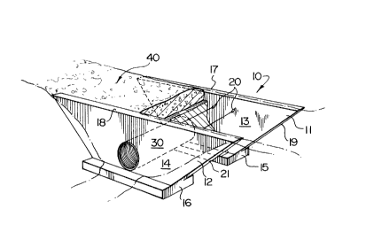
Figure 1 is a perspective view, partially in
assembly, of a culvert end wall retainer system according to
my invention;
Figure 2 is a side elevational view of one of the
side walls;
Figure 3 is an end elevational view of the side
wall of Figure 2;
Figure 4 is a top plan view of the side walls
assembled prior to backfilling the plenum between the side
wall with aggregate.
The culvert end wall retainer system is generally shown


2129191


as (10) in Figure 1 and consists of two mirror side walls
(11) and (12), each respectively composed of a vertical
section (13,14) and an orthogonally oriented base portion or
slab (15) and (16).
The vertical sections (13,14) have respective tops (17)
and (18) and incl~ned ends (19) and (21). The slope that the
ends (19) and (20) ~espectively mate with their base slabs
(15,16) will dèpend upon the depth of the culvert to be
constructed. Similarly, the length of the shorter base piece
(15,16), shown with dimension (B) in the side view of Figure
2, will depend as to how wide the base of the drainage region
for the culvert is to be. It can be varied. So can the top
dimension (T) so as to accommodate the upper shoulder width
of the drainage ditch in which the culvert rests. Each
mirror side wall (11,12) defines a drainage aperture (A), and
now referring back to Figure 1, the apertures (A)
communicating with a corrugated steel pipe (30) extending
between the mirror side walls (11) and (12) through which the
water and other drainage material will pass.
On the inside surfaces of each mirror side wall (11)
and (12) are spatially disposed stainless loops or hooks
(20). They are embedded into the sections (13) and (14)
during casting. After casting the end walls (11,12), they are
re-located to the culvert site and erected vertically, as-
illustrated in the perspective Figure 1; and, stainless steel
wires or rods (22) are extended from one loop l20) to the
opposite loop (20) in the other mirror wall, in the fashion
illustrated in Figure 4. Thereafter, and now referring to
Figure 1, the space between the side walls can be filled with
the necessary aggregate, generally shown as (40) in that
figure and thereafter a topping put on, if required, for
instance gravel, asphalt or concrete in order to provide the
bearing surface for the roadway.
Referring to the side elevational view, Figure 2 and
the end elevational view, Figure 3 of the culvert end wall,
in phantom and unreferenced, there are shown two rectangular
recesses with a cylindrical lateral member. These same
recesses and the cylindrical lateral member, as shown in the


4 2129191

top elevational view of Figure 4, these recesses and the
cylindrical member act as "pins" whereby the culvert end wall
(13,14) may be lifted, using a hook extending beneath each
pin, and therefore moved and placed into position in the
culvert, shown in the perspective view of Figure 1. These
recesses and pins are not shown in that figure. This
facilitates easy handling of each end wall for removal from
one manufacturing site to the in situ site where the culvert
is to be fabricated.

Representative Drawing
A single figure which represents the drawing illustrating the invention.
Administrative Status

For a clearer understanding of the status of the application/patent presented on this page, the site Disclaimer , as well as the definitions for Patent , Administrative Status , Maintenance Fee  and Payment History  should be consulted.

Administrative Status

Title Date
Forecasted Issue Date 1998-11-17
(22) Filed 1994-07-29
Examination Requested 1994-11-04
(41) Open to Public Inspection 1996-01-30
(45) Issued 1998-11-17
Deemed Expired 2005-07-29

Abandonment History

There is no abandonment history.

Payment History

Fee Type Anniversary Year Due Date Amount Paid Paid Date
Application Fee $0.00 1994-07-29
Maintenance Fee - Application - New Act 2 1996-07-29 $50.00 1996-07-26
Maintenance Fee - Application - New Act 3 1997-07-29 $50.00 1997-07-25
Final Fee $150.00 1998-03-23
Maintenance Fee - Application - New Act 4 1998-07-29 $50.00 1998-07-29
Maintenance Fee - Patent - New Act 5 1999-07-29 $75.00 1999-07-29
Maintenance Fee - Patent - New Act 6 2000-07-31 $75.00 2000-07-13
Maintenance Fee - Patent - New Act 7 2001-07-30 $75.00 2001-07-29
Maintenance Fee - Patent - New Act 8 2002-07-29 $75.00 2002-07-19
Maintenance Fee - Patent - New Act 9 2003-07-29 $75.00 2003-07-29
Owners on Record

Note: Records showing the ownership history in alphabetical order.

Current Owners on Record
GOODREAU, EUGENE ALFRED
Past Owners on Record
None
Past Owners that do not appear in the "Owners on Record" listing will appear in other documentation within the application.
Documents

To view selected files, please enter reCAPTCHA code :


To view images, click a link in the Document Description column. To download the documents, select one or more checkboxes in the first column and then click the "Download Selected in PDF format (Zip Archive)" or the "Download Selected as Single PDF" button.

List of published and non-published patent-specific documents on the CPD .

If you have any difficulty accessing content, you can call the Client Service Centre at 1-866-997-1936 or send them an e-mail at CIPO Client Service Centre.


Document
Description 
Date
(yyyy-mm-dd) 
Number of pages   Size of Image (KB) 
Representative Drawing 1998-08-04 1 12
Cover Page 1996-03-22 1 14
Abstract 1996-01-30 1 20
Description 1996-01-30 4 176
Claims 1996-01-30 2 76
Drawings 1996-01-30 1 29
Description 1997-06-11 4 174
Claims 1997-06-11 2 75
Cover Page 1998-10-29 1 45
Correspondence 1998-03-23 1 49
Correspondence 1998-10-02 1 3
Correspondence 1998-10-21 1 2
Correspondence 1998-10-28 1 13
Fees 2000-07-13 1 75
Fees 2003-07-29 1 85
Fees 1998-09-28 6 499
Fees 1999-07-12 1 37
Fees 2001-07-29 3 138
Fees 2002-07-19 1 79
Fees 1997-07-25 1 40
Prosecution Correspondence 1994-11-04 1 43
Prosecution Correspondence 1996-09-20 1 34
Prosecution Correspondence 1995-11-24 4 187
Office Letter 1995-02-18 1 39
PCT Correspondence 1995-03-16 1 32
Fees 1998-09-17 9 254
Fees 1996-07-26 1 39