Language selection

Search

Patent 2129209 Summary

Third-party information liability

Some of the information on this Web page has been provided by external sources. The Government of Canada is not responsible for the accuracy, reliability or currency of the information supplied by external sources. Users wishing to rely upon this information should consult directly with the source of the information. Content provided by external sources is not subject to official languages, privacy and accessibility requirements.

Claims and Abstract availability

Any discrepancies in the text and image of the Claims and Abstract are due to differing posting times. Text of the Claims and Abstract are posted:

  • At the time the application is open to public inspection;
  • At the time of issue of the patent (grant).
(12) Patent: (11) CA 2129209
(54) English Title: FISHING TACKLE LURE
(54) French Title: AGRES DE PECHE
Status: Deemed expired
Bibliographic Data
(51) International Patent Classification (IPC):
  • A01K 85/14 (2006.01)
(72) Inventors :
  • GABOS, JOHN J. (United States of America)
  • OLENEK, MICHAEL V. (United States of America)
(73) Owners :
  • GABOS, JOHN J. (United States of America)
  • OLENEK, MICHAEL V. (United States of America)
(71) Applicants :
  • GABOS, JOHN J. (United States of America)
  • OLENEK, MICHAEL V. (United States of America)
(74) Agent: BORDEN LADNER GERVAIS LLP
(74) Associate agent:
(45) Issued: 1999-04-27
(22) Filed Date: 1994-07-29
(41) Open to Public Inspection: 1995-03-31
Examination requested: 1994-07-29
Availability of licence: N/A
(25) Language of filing: English

Patent Cooperation Treaty (PCT): No

(30) Application Priority Data:
Application No. Country/Territory Date
08/129,469 United States of America 1993-09-30

Abstracts

English Abstract


A spoon lure for fishing in fresh water or sea
water, comprised of a wedge-shaped strip of highly
reflective metal or any other suitable material that
is bent to a radius along its length and width, with a
rudder at the wide end of the wedge set at an angle to
the length of the body and rolled in the opposite
direction of the radius. At the narrow end of the
wedge, or the leading edge, there is a hole for
fastening a swivel device which in turn is fastened to
a fishing line. At the wide end, or trailing edge,
there are two holes for fastening a hook. One hole is
on center of the wide end at the base of the rolled
wing and one hole is on the corner opposite the rolled
rudder. This configuration results in a lure that
will spin through the water with a tight pattern when
the hook is placed in the center hole. When the hook
is moved to the corner hole, the action changes to a
slower spin with a random dodging or darting motion,
resulting in a much wider pattern. In addition to two
different actions when the lure is being drawn through
the water, a third aggressive action is evident when
the lure is used in a jigging or flipping
presentation.


French Abstract

Cette invention concerne une cuiller de pêche en eau douce et en mer qui comprend une bande de métal ou autre matériau hautement réfléchissant en forme de coin courbé dans le sens de la longueur et de la largeur et comportant à son bout large un aileron incliné par rapport à son axe longitudinal et incurvé dans le sens contraire de sa courbure. Au bout effilé du coin, c'est-à-dire à son avant, est prévu un trou pour la fixation d'un émerillon à être attaché à la ligne. € l'autre bout, soit l'arrière, il y a deux trous destinés à la fixation d'un hameçon. Un des trous est centré à la base de l'aileron et l'autre se trouve dans le coin opposé à celui-ci. Cette configuration donne une cuiller qui tourne en hélice serrée avec l'hameçon accroché dans le trou centré et qui tourne plus lentement, de façon erratique et en balayant plus large avec l'hameçon fixé dans l'autre trou. En plus de pouvoir se comporter de deux façons différentes, cette cuiller présente une action plus agressive à la pêche à la dandinette.

Claims

Note: Claims are shown in the official language in which they were submitted.


-6-
THE EMBODIMENTS OF THE INVENTION IN WHICH AN EXCLUSIVE
PROPERTY OR PRIVILEGE IS CLAIMED ARE DEFINED AS FOLLOWS:

1. A fishing lure comprising a body of
generally wedge-shaped outline having a wide end and a
narrow end with a longitudinal axis extending
therebetween, the width of said wedge-shaped body
tapering gradually from the wide end to the narrow
end, said body having a transverse cross section of
arcuate form providing a convex surface on one side
and a concave surface on the opposite side, said
convex surface defining a longitudinally-extending
bowl-shaped convex surface on said one side and said
concave surface defining a longitudinally-extending
bowl-shaped hollow surface on said opposite side, at
the opposite ends of the longitudinal axis said lure
having eyelets for attachment of said lure to a
fishing line at the narrow end and for attachment of
said lure to a fishing hook at the wide end, whereby
when said fishing hook is drawn through the water by
the fishing line, the lure causes the hook to follow a
path simulating the travel of a bait fish, the
improvement wherein
said lure has a rudder component at the wide
end thereof, said component comprising a tab bent out
from said bowl-shaped convex surface along a bending
line at the wide end, said bending line being disposed
at an acute angle to the longitudinal axis of the lure
and offset laterally therefrom, and
said wide end has a second eyelet for
alternative attachment to a fishing hook, said
wide-end eyelets being spaced laterally from said bent-out
tab, and being aligned with said tab transversely of
said longitudinal axis.

2. A fishing lure according to claim 1,
wherein one of said eyelets at the wide end is along
the longitudinal axis of the lure, and the other of


-7-

said eyelets at the wide end is offset from said
longitudinal axis away from said tab bending line.

3. A fishing lure according to claim 1 wherein
said longitudinal axis has a radius of curvature
providing said bowl-shaped surfaces, and the arcuate
transverse cross section has a radius of curvature no
smaller than said radius of curvature of the
longitudinal axis.

4. A fishing lure according to claim 3 wherein
said transverse radius of curvature is between one and
two times the longitudinal radius of curvature.

5. A fishing lure according to claim 1 wherein
said bending line of the tab provides a streamlined
surface.

6. Fishing tackle comprising a rod, a reel,
fishing line and a fish hook, the improvement
comprising a lure adapted to be mounted intermediate
the fish hook and the fish line, said lure comprising
a body of generally wedge-shaped outline having a wide
end and a narrow end, the width of said wedge-shaped
body tapering gradually from the wide end to the
narrow end, with a bowl-shaped convex surface on one
side and a bowl-shaped hollow surface on the opposite
side, means attaching the narrow end to the fishing
line at the center of the narrow end, and primary
means attaching the wide end to the fishing hook at
the center of the wide end, said lure having a central
longitudinal axis extending between said respective
attaching means,
said lure further comprising an alternative
auxiliary means for attaching said hook at the wide
end of said wedge-shaped outline, said alternative
attaching means being offset laterally from said


-8-
longitudinal axis, said primary and alternative
attaching means being aligned transversely of said
central longitudinal axis,
said lure also having a rudder at the wide
end of the lure in alignment with said primary and
alternative attaching means, said rudder being bent
out from the convex surface away from the concave
surface along a bending line at an acute angle to said
longitudinal axis at a position offset from the
longitudinal axis opposite said auxiliary attaching
means,
whereby the travel of the lure through the
water is affected by changing the connection of the
hook between said primary and alternative attaching
means without removing the attachment means at the
opposite end of the lure from the line.

7. Fishing tackle according to claim 6 wherein
said attaching means at the narrow end of the lure
comprises a swivel connection in the fishing line
between said rod and said lure.

Description

Note: Descriptions are shown in the official language in which they were submitted.


~l2.~2as
FISHING ~ACRLE LURE
John J. Gabos - Weatherly, PA
Michael V. Olenek - Hazleton, PA

FIEI.D OF THB lNV~ih.L101~
The present invention relates to fishing tackle
and more particularly to fishing tackle which includes
an improved lure of the spoon type.

B~CRGRO~JND OF THE lNV~;h~lON
The invention concerns an artificial fishing lure
that can be used in bo~h fresh and salt water. The
lure is a wedge-shaped spoon that has a hole in the
narrow end for fastening a swivel device which, in
turn, will be fastened to a fishing line. The
opposite end, or the wide end of the lure, has two
holes for fastening a hook with a wire. One hole is
on center and one hole is on the corner opposite the
rolled wing. The spoon is bent into a radius along
its length and width resulting in a spoon shape. The
wide end is rolled at an angle to the length and is
the opposite direction of the radius. As the spoon is -
drawn through the water, it will either spin in a
tight pattern or spin slowly in a wide pattern with a
random dodge or dart, depending on the position of the
hook at the rear of the lure. When the lure is
dropped or flipped into the water and allowed to fall
through the water at its own speed, it displays a very
wide, slow, random action as it descends.
After studying a collection of prior spoon-type
lures, it is obvious the intensity of the action
changes with a change in speed - basically the same
motion at different intensities. The present
invention provides three different motions, i.e. two
by changing the hook position and one by changing the
presentation. A wide variety of lures can be
manufactured by combining these actions with a variety
of finishes and colors.

CA 02129209 1999-02-17 P.2


'' ' ' ''''' ' ' '
!
OBJ~ ApD ~MMAR~ O~ ~HJ INVBN~IO~
one object of thi8 invention i~ to provid~ a
variety of action~ from ~ single lure.
s Another object o~ thi~ in~ention i~ to produce a
novel lure that allows ~imple and ~oonomical
manufacture.
Sp~ci~ical}y, the ~nvention p~ovide~ a lure o~ a
no~el configu~ation which ~ay be manufactured from any
highly re~lective metal or any accep~able material.
~h~ size of ~he lure, the ratio of the radi~, and the
orientation o~ the ~udder may be modifie~ to ~pki~ze
the lure. ~he lure provide~ a simple base to apply a
var~e~y of colors and finishe~.

RDT~F D~ r~c~ OF ~r~ H~oLi
Al} of t~ objects of the inven~ion are mor-3
~ully set for~h hereina~ter with r~feren¢e to ~he
accompanying drawings ~ wherein:
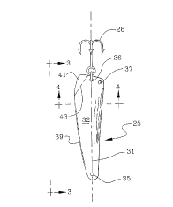
Fig~ 1 i~ an e~e~atlonal view o~ h;~ tackle
20 embcdying the pre~ent in~enti.on;
Fig. 2 i~i an enlarged plan view o~ the lure shown
in Fig. l;
Fig. 3 i~ a le~thand e}e~ational ~iew a~ s~en
from the line 3-3 of Fig. 2; and
Fig. 4 i~ a tra~ be sectional view taken on
t}~e lin~ 4-4 of ~ig. a.

~p~TO~. ~Y ~K~ ~R~r~Y~ YllR~p~E~rr
Re~erring to the drawing~, Fig. 1 ~ llustrate~
fishing tackle embodying ~n ~ ~roved lure in
ac¢ordance wit~ the ~r~,l~ invention. A~ ~hown, the
~ackle comprise~; a ro~l al having ~ reel aa and a
fi~hing line 23. q~}~e line i8 threaded through the
line guides of the rod and terminate~ in a 8wiV~31 24

212~3
3 --

to which a novel lure 25 is secured. The lure has a
generally wedge-shaped outline and is connected to the
swivel at the narrow end and a hook 26 is connected to
the lure at the wide end. As shown in Figs. 2-4, the
wedge-shaped lure has a longitudinal axis 31 which has
a longitudinal curvature providing a concavity 32
extending from end to end. Transversely, the lure has
a shallow arcuate form as shown at 33 in Fig. 4 which
cooperates with the concavity 32 to define a hollow
bowl-like surface on one side of the lure. The lure
is made of a material with substantially uniform
thickness throughout so that the opposite side of the
lure provides a convex bowl-like surface. Preferably,
the curvature àlong the longitu~;n~l axis is smaller
than along the transverse axis, i.e. the radius of
curvature is larger along the transverse axis than the
radius of curvature along the longitu~; na ~ axis. The
ratio of the two radii of curvature will fall between
1:1 and 2:1.
At the narrow end of the wedge-shaped outline,
the lure is provided with an eyelet 35 for attachment
to the swivel 24. At the wide end of the wedge-shaped
outline, the lure has an eyelet 36 approximately on
the longitu~in~l axis 31 and a second eyelet 37 offset
from the longitll~inAl axis 31 so that the eyelet 37 is
positioned adjacent a longit~l~in~l edge 38 of the
lure. At the opposite longit~i n~ I edge of the lure,
a tab 41 is bent outwardly in a direction away from
the concave surface of the lure 25 along an angular
bending line 43 which is disposed at an acute angle to
the longitudinal axis 31 and offset from the axis
opposite to the offset of the eyelet 37 from the
longitu~inal axis. In the present instance, the
be~ing line has a radius of curvature which is
smaller than the radius of curvature in the body of
the lure along the longitudinal and transverse axes.
In the present instance, the tab is rolled out from
.

~1~92~9
-- 4

the body of the lure with a smooth curvature at its
hook end.
The material of the lure is preferably reflective
sheet material of uniform thickness. The lure may be
stamped from stainless steel or copper, or be molded
from plastic. The finish may be shiny, smooth,
mottled or painted and~or any combination of the
above.
In operation, the lure is secured to the fi~h;ng
line through a swivel as shown in Fig. 1. When the
lure is dropped or flipped into the water and allowed
to fall through the water at its own speed, it
displays a very wide slow random action as it
descends. If the hook is placed in the center hole 36
as shown, when the lure is drawn through the water, it
will spin with a tight pattern. When the hook is
moved to the other hole 37, the action of the lure as
it is drawn through the water changes to a slower spin
with a random dodging or darting motion, resulting in
a much wider pattern. The changing of the hook hole
may be done without removing the lure from the fishing
line. In addition to the two different actions when
the lure is being drawn through the water, a third
aggressive action is evident when the lure is used in
a jigging or flipping presentation. Thus, the design
of the lure affords a wide variety of actions caused
by the manner in which it i~ used. The skilled
fisherman can operate the lure to simulate the action
of a bait fish, as desired. The lure may be used for
cast-and-retrieve, trolling, jigging, or flipping, and
for all types of sport or commercial fishing.
The presentation of the lure may be varied
according to the desires of the fisherman and the
geometry of the lure may be modified to achieve varied
effects. Preferably, the material of the lure is
sufficiently rigid to avoid inadvertent flexing or
deformation. If made of stainless steel or copper, it


' ,; . ' . ' ' ' ~ ~ ' ' ~

'.'.' ' ' , , ~ ,'~ ' , ' :

~2~2a9

may be modified by the fisherman by bending or shaping
the metal to achieve differing effects. With the use
of the two holes at the hook end of the lure, a
different action is achieved, depending upon the
selection of which hole. The curved configuration of
the body of the lure and the curvature of the merger
of the tab 41 with the lure provides a streamlined
surface which is believed to contribute to the novel
action achieved by the lure as it is drawn through the
water.
While a particular embodiment of the invention
has been herein illustrated and described, it is not
intended to limit the invention to such disclosures,
but changes and modifications may be made therein and
thereto within the scope of the following claims.

Representative Drawing
A single figure which represents the drawing illustrating the invention.
Administrative Status

For a clearer understanding of the status of the application/patent presented on this page, the site Disclaimer , as well as the definitions for Patent , Administrative Status , Maintenance Fee  and Payment History  should be consulted.

Administrative Status

Title Date
Forecasted Issue Date 1999-04-27
(22) Filed 1994-07-29
Examination Requested 1994-07-29
(41) Open to Public Inspection 1995-03-31
(45) Issued 1999-04-27
Deemed Expired 2003-07-29

Abandonment History

There is no abandonment history.

Payment History

Fee Type Anniversary Year Due Date Amount Paid Paid Date
Request for Examination $200.00 1994-07-29
Application Fee $0.00 1994-07-29
Maintenance Fee - Application - New Act 2 1996-07-29 $50.00 1996-06-14
Maintenance Fee - Application - New Act 3 1997-07-29 $50.00 1997-07-02
Maintenance Fee - Application - New Act 4 1998-07-29 $50.00 1998-07-15
Final Fee $150.00 1998-11-24
Maintenance Fee - Patent - New Act 5 1999-07-29 $75.00 1999-07-16
Maintenance Fee - Patent - New Act 6 2000-07-31 $75.00 2000-07-20
Maintenance Fee - Patent - New Act 7 2001-07-30 $75.00 2001-07-20
Owners on Record

Note: Records showing the ownership history in alphabetical order.

Current Owners on Record
GABOS, JOHN J.
OLENEK, MICHAEL V.
Past Owners on Record
None
Past Owners that do not appear in the "Owners on Record" listing will appear in other documentation within the application.
Documents

To view selected files, please enter reCAPTCHA code :


To view images, click a link in the Document Description column. To download the documents, select one or more checkboxes in the first column and then click the "Download Selected in PDF format (Zip Archive)" or the "Download Selected as Single PDF" button.

List of published and non-published patent-specific documents on the CPD .

If you have any difficulty accessing content, you can call the Client Service Centre at 1-866-997-1936 or send them an e-mail at CIPO Client Service Centre.


Document
Description 
Date
(yyyy-mm-dd) 
Number of pages   Size of Image (KB) 
Cover Page 1995-06-05 1 58
Representative Drawing 1998-06-30 1 5
Abstract 1995-06-05 1 48
Claims 1995-06-05 3 150
Drawings 1995-06-05 2 89
Description 1999-02-17 5 241
Cover Page 1999-04-22 1 54
Representative Drawing 1999-04-22 1 3
Correspondence 1998-11-24 1 35
Prosecution Correspondence 1996-11-15 1 29
Prosecution Correspondence 1999-02-17 1 31
Fees 1996-06-14 1 46