Note: Descriptions are shown in the official language in which they were submitted.
2~.~~3~ f~~
Method and device for determining characteristics of the
flow of a medium
BACKGROUND OF THE INVENTION
The present application relates to a method for
determining characteristics of the flow of a medium in a
channel by transmitting and receiving sound waves along one
or more acoustic paths using one or more acoustic
transducers, each of which can act individually as a
transmitter and receiver, and by measuring the transit
times of the transmitted sound waves, and determining
characteristics from the measured transit times.
Such a method is generally known. It involves
determining the average flow velocity and/or the throughput
of the medium from the difference in transit time of sound
waves which are transmitted in the downstream direction and
upstream direction respectively between acoustic trans-
ducers set up at a distance from each other. The medium can
be a gas or liquid.
The transit times of the sound waves not only
depend on the flow velocity of the medium, but are also
influenced by the flow profile of the medium. In a flowing
medium, apart from the longitudinal movement, a swirl can
occur. Other possible disturbances of the ideal flow
profile are a flow velocity fluctuating in time and a flow
profile which is asymmetrical relative to the longitudinal
axis. Such disturbances occur in particular in pipe systems
which have a complex structure.
The ultimate reliability of the calculated flow
velocity of the medium depends on the distance covered, the
,acoustic path, on the transmitted sound wave, and on the
calculation method used. Many configurations are known for
the acoustic path.
In the case of the conventional methods which are
used in commercially available measuring instruments,
several acoustic paths are used, running parallel to each
other. The known numerical Gaussian square method is used
for positioning of the paths and the various weighting
factors which are allocated to the measured velocities.
~1293R~
- 2 -
The advantages of this method are clear. No
additional information on the flow profile is required for
calculating the velocity. The weighting factors are fixed
in advance, so that the microprocessor which is used for
calculation of the characteristics need only carry out a
limited number of calculations.
Although this means that measurement of the flow
velocity is simple to carry out and excellent results can
be obtained in ideal flow conditions, the method has a
number of clear disadvantages, due to the underlying
assumptions and limitations of the Gaussian integration
method. These underlying assumptions and limitations are as
follows:
- It is assumed that the flow profile is fully axially
symmetrical.
- No additional information from the Reynolds number is
used.
- As a result of the fixed weighting factors for the
various acoustic paths, which are optimized for the
undisturbed flow profile, errors will occur when the
actual flow profile deviates from the ideal profile.
OBJECTS OF THE INVENTION
The object of the present invention is to provide a
method for determining characteristics of the flow of a
medium in a channel, such as swirl and symmetry.
Another object of the present invention is to
provide a method for determining the flow velocity and/or
throughput of a medium in a channel with more accurate
results, due to the fact that errors caused by disturbances
of the ideal flow profile are eliminated.
SLJ~MMARY OF THE INVENTION
The method according to the invention of the
abovementioned type is characterized in that at least two
sound waves whose transit time depends on swirl are
transmitted along acoustic paths with a different sensi-
2~2'~:~~?'~'
- 3 -
tivity to swirl, and a measure of the swirl in the flow is
determined from the measured transit times.
DETAILED DESCRIPTION OF THE INVENTION
In the case of this method, sound waves are trans-
mitted along acoustic paths with a different sensitivity to
swirl.
Firstly, this can mean that a first sound wave is
transmitted in a stationary medium in a plane at right
angles to the direction of flow (the sensitivity to swirl
is zero at this so-called calibration standard), and a
second sound wave is then transmitted along the same
acoustic path in a flowing medium, in which the sensitivity
to swirl is different.
Secondly, this can mean that sound waves are
transmitted along different acoustic paths which are sensi-
tive to swirl, in the same direction of flow of the flowing
medium, either downstream or upstream.
A measure of the swirl can be determined from
comparison of the measured transit times of the transmitted
sound waves along acoustic paths with a different
sensitivity to swirl. If the measured transit times are
identical, there is no swirl. If the measured transit times
are not identical, the difference in transit time is a
measure of the intensity of the swirl. This measure of the
intensity contains both the magnitude and the direction of
the swirl.
The channel in which the method is carried out will
in many cases be a cylindrical pipe, but the method can
'also be used in channels of other shapes, such as a square
cross-section or a U-shaped channel.
The method can be used advantageously in a
cylindrical pipe through sound waves whose transit time
depends on swirl being transmitted along various acoustic
paths with at least two reflections against the wall of the
channel, and at least one sound wave being transmitted
clockwise and at least one sound wave in a direct~.on
opposite thereto. The sound waveso two reflections of which
212
- 4 -
are taken up in the acoustic path, traverse a large part of
the cross-section of the channel and thus give a reliable
picture of the flow.
Another embodiment of the acoustic path of sound
waves whose transit time depends on swirl is an acoustic
path without reflection against the wall of the channel.
The invention also relates to a method of the
abovementioned type which is characterized in that at least
two sound waves whose transit time depends on the symmetry
of the flow profile are transmitted along acoustic paths
with a different sensitivity to symmetry, and a measure of
the symmetry of the flow profile is determined from the
measured transit times thereof.
In the case of this method, sound waves are
transmitted along acoustic paths which are sensitive to
asymmetrical flow profiles. In a similar way to that
described above for determining a measure of the swirl, a
measure of the symmetry can be derived from the difference
in transit time of said sound waves.
The above-described methods are advantageously
combined by transmitting both sound waves whose transit
time depends on swirl along acoustic paths with a different
sensitivity to swirl and sound waves whose transit time
depends on symmetry along acoustic paths with a different
sensitivity to symmetry, and determining a measure of the
swirl in the flow and a measure of the symmetry of the flow
profile from the measured transit times.
The sound waves whose transit time depends on the
symmetry of the flow profile are preferably transmitted
along different acoustic paths with one reflection against
'the wall of the channel, in which case the acoustic paths
cross the longitudinal axis of the channel. Such sound
waves are preferably transmitted along three different
acoustic paths, so that the sound waves traverse the entire
cross-section of the channel.
The method according to the invention first of all
gives an insight into the possible presence and magnitude
of disturbances of the ideal flow profile, such as swirl
and asymmetry.
2~.~~~~~~
If the transit times of sound waves along the
various acoustic paths in a stationary flow are known, for
example by means of calibration, the average flow velocity
and/or the throughput of the medium can be calculated from
the difference in transit time of sound waves in a
stationary and flowing medium respectively along the same
acoustic path.
However, prior calibration is not necessary. For
this purpose, two sound waves are advantageously trans-
mitted along an acoustic path in the downstream and
upstream direction respectively. Two sound waves are
preferably transmitted along each acoustic path in the
downstream and upstream direction respectively. The average
flow velocity can be determined from the difference in
transit time of sound waves transmitted along the same
acoustic path, but in opposite directions of flow.
In order also to detect the presence of a flow
which fluctuates in time, several sound waves are prefer-
ably transmitted in rapid succession along the same
acoustic path, and a measure of the pulsation of the flow
of the medium is determined from the measured transit times
thereof. The difference in transit time of two sound waves
transmitted in rapid succession along the same acoustic
path is a measure of the fluctuation in time of the flow of
the medium.
A weighting factor is advantageously allocated to
the measure of a characteristic, and by means thereof and
the individual velocities along the various acoustic paths
the flow velocity and/or the throughput of the medium in
the channel is determined.
The method is preferably carried out by allocating
weighting factors to the measure of swirl and symmetry, and
if desired the pulsation, and by means thereof and the
individual velocities along the various acoustic paths
calculating the flow velocity and/or the throughput of the
medium in the channel. Since account is taken of possible
disturbances when calculating the flow velocity and/or the
throughput of the medium, a reliable value is obtained for
them. The Reynolds number is advantageously involved in the
21~~3R~;
calculation of the flow velocity and/or the throughput of
the medium. The accuracy of such a measurement is better
than 0.3% of the calculated value for flow velocities of
0.3 to 30 m/s (1 to 100 foot/sec).
The individual velocities along the various
acoustic paths can be determined either by a prior calibra-
tion or by measuring the transit time of sound waves
transmitted along the same acoustic path in the downstream
and upstream directions respectively, as described above.
Measurements by means of the method according to
the invention can be carried out simply in complex pipe
systems, without the flow of the medium having to be evened
out by flow elements or other aids.
The present invention also relates to a device for
determining characteristics of the flow of a medium in a
channel, which device comprises one or more acoustic trans-
ducers, each of which can act individually as a transmitter
and receiver for transmitting sound waves along acoustic
paths and receiving thereof, and means for measuring the
transit time of the transmitted sound waves, and means for
determining the characteristics from the measured transit
times. Such a device is also generally known from the prior
art.
The device according to the invention is charac-
terized in that the device comprises at least two pairs of
acoustic transducers, in which the transducers transmit a
sound wave whose transit time depends on swirl along
acoustic paths with a different sensitivity to swirl, and
the means for determining the characteristics from the
measured transit times determine a measure of the swirl.
' The transducers transmitting sound waves whose
transit time depends on swirl advantageously transmit sound
waves along acoustic paths with at least two reflections
against the wall of the channel, and at least one sound
wave thereof is in the clockwise direction, while at least
one sound wave is in the opposite direction. In another
embodiment of the device according to the invention, the
transducers transmitting sound waves whose transit time
depends on swirl transmit sound waves along acoustic paths
2~2~3'~~f
-
without reflection against the wall of the channel.
Another embodiment of the device of the above-
mentioned type according to the invention is characterized
in that the device has at least two pairs of transducers,
in which the transducers transmit a sound wave whose
transit time depends on the symmetry of the flow profile
along acoustic paths with a different sensitivity to
symmetry, and the means for determining the characteristics
from the measured transit times determine a measure of the
symmetry of the flow profile.
In a preferred embodiment of the device according
to the invention, the device comprises at least two pairs
of acoustic transducers, in which the transducers transmit
a sound wave whose transit time depends on swirl along
acoustic paths with a different sensitivity to swirl and at
least two pairs of transducers, in which the transducers
transmit a sound wave whose transit time depends on the
symmetry of the flow profile along acoustic paths with a
different sensitivity to symmetry, and the means for
determining the characteristics from the measured transit
times determine a measure of the swirl and a measure of the
symmetry of the flow profile.
With these devices according to the invention an
insight can be gained into the type of flow of the.medium.
The transducers which transmit sound waves whose
transit time depends on the symmetry of the flow profile
expediently transmit sound waves along various acoustic
paths with one reflection against the wall of the channel,
which acoustic paths cross the longitudinal axis of the
channel. The device is preferably provided with three pairs
of such transducers, so that the sound waves which are
transmitted along the various acoustic paths scan the
entire cross-section of the channel.
A pair of transducers advantageously sends two
sound waves along the same acoustic path in the downstream
direction and upstream direction respectively, so that the
means for determining the characteristics from the measured
transit times can determine the flow velocity along said
acoustic path. Each pair of transducers preferably
- 212J~u;~
transmits sound waves along each acoustic path in the down-
stream direction and upstream direction respectively.
In order also to determine the measure of pulsation
of the flow with the device according to the invention, the
transducers can be designed to transmit several sound waves
in rapid succession along the same acoustic path, and the
means for determining the characteristics from the measured
transit times also determine a measure of the pulsation.
In order to permit use of the device as a
flowmeter, the means for determining the characteristics
calculate the flow velocity and/or the throughput of the
medium from the measure of a characteristic and the
individual velocities along the various acoustic paths.
The means for determining the characteristics
advantageously calculate the flow velocity and/or the
throughput of the medium from the measure of the swirl and
symmetry, and if desired the pulsation and the individual
velocities, along the various acoustic paths.
BRIEF DESCRIPTION OF THE DRAWING
The invention will be explained in greater detail
below with reference to the appended drawing, in which:
Fig. 1 is a projection of various acoustic paths of
the transmitted sound waves according to the invention;
Fig. 2 is a view of an acoustic path with a single
reflection; and
Fig. 3 is a view of an acoustic path with a double
reflection.
DESCRIPTION OF THE PREFERRED EMBODIMENT
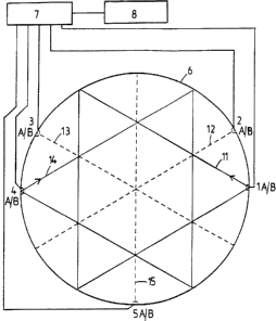
Fig. 1 shows a configuration of acoustic paths of
the sound waves according to a preferred embodiment of the
invention. In the situation shown, the channel is a
cylindrical pipe 6. The reference numbers 1A/B to 5A/B
indicate pairs of transducers set up at a distance from
each other, which transducers can act as transmitters and
receivers. The transducers 1A and 4A transmit sound waves
,,,,,.,,
~129~~''~'
_ 9 _
(indicated by a solid line) along various acoustic paths
with two reflections, a sound wave 11 being transmitted in
an anticlockwise direction, and a sound wave 14 in a
clockwise direction. The acoustic paths of the sound waves
11 and 14 have a different sensitivity to swirl in the
flow. The transmitted sound waves are received by the
transducers 1B and 4B respectively. Said transducers iB and
4B themselves transmit sound waves (not shown) in the
opposite direction along the acoustic paths with two
reflections, which sound waves are received by the
transducers 1A and 4A. The transmitted sound waves 11 and
14 and the sound waves transmitted in the opposite
direction traverse a large part of the cross-section of the
channel 6. The transit time of the sound waves between the
transducers depends on swirl.
The transducers 2A, 3A and 5A transmit sound waves
12, 13 and 15 respectively (shown by a dashed line) with a
single reflection against the wall of the channel 6. The
acoustic paths of the sound waves 12, 13 and 15 have a
different sensitivity to the symmetry of the flow profile.
The transducers 2B, 3B and 5B receive said sound waves and
themselves transmit sound waves in the opposite direction
along different acoustic paths. The sound waves cross the
longitudinal axis of the channel 5. The transit time of
said sound waves depends on the symmetry of the flow.
Reference number 7 indicates diagrammatically means
for measuring the transit time of the sound waves. Said
means 7 are connected to the transmitters and receivers.
Means 8 for determining the characteristics of the flow,
such as the intensity of the swirl and asymmetry of the
flow profile, are also shown diagrammatically.
Figs. 2 and 3 show acoustic paths with a single and
double reflection respectively between a transmitter A and
receiver B. The arrow v", indicates the direction of flow of v
the medium.
Examples of the interpretation and processing of
the measured transit times of sound waves with acoustic
paths, as shown in Fig. i, are given below.
The results are presented in the form of a matrix.
_ to _ 2~~~3a~'
The table below is an example of such a matrix.
Table 1
Identical
Yes No
Low Ave- High
rage
Paths sensitiveFluctuations Yes
to symmetry No
Paths sensitiveFluctuations Yes
to swirl No
Reynolds number
The transit times of the sound waves transmitted in
the same direction of flow along different acoustic paths
which are sensitive to symmetry are compared. If there are
deviations, a distinction is made in the size of the
differences measured. The deviations are broken down into
one or more of three categories, namely low, average and
high. This means that in that case a low, average and high
deviation of the symmetry in the flow is present. Of
course, more or fewer categories may be used if desired.
The transit times of the sound waves which are
sensitive to swirl of the flow are also compared arid, if
there are deviations, they are broken down into one of the
three categories.
For each type of sound wave it is also ascertained
whether the flow velocity fluctuates in time.
The flow velocity of the medium is also calculated
for each acoustic path from the difference in transit time
of sound waves which are transmitted along the same
~acoustic''path in the downstream and upstream direction.
The flow velocity and/or the throughput are
calculated with the aid of this matrix and weighting
factors to be allocated to it and the individual velocities
along the various acoustic paths.
EXAMPLES
Two examples of flaw profiles and the corresponding
2~2~~3~:'
- 11 -
matrix are given below.
Example 1
In Table 2 below the flow behaviour of a medium
with an ideal flow profile is characterized. In this table
"0" means absent and "X" means present.
Identical
Yes No
Low Ave-High
rage
Paths sensitiveFluctuationsYes 0 0 0 0
to symmetry No X 0 0 0
Paths sensitiveFluctuationsYes 0 0 0 0
to swirl No X 0 0 0
Reynolds number X 0 0 0
In thereare erences
an no in
ideal diff
flow
profile
the wnstream upstream)
transit or
times
of
sound
waves
(do
along and fluctuatio ns the
similar no of
acoustic
paths,
flow
velocity
in
time
occur.
Example 2
Table 3 below shows the behaviour of a medium after
a double bend in a compressor station.
Identical
Yes No
Low Ave- High
rage
Paths sensitiveFluctuations X 0 X X
Yes
to symmetry No 0 0 o 0
Paths sensitiveFluctuations 0 0 X X
Yes
to swirl No X 0 0 0
Reynolds number X 0 X X
Table 2 Ideal flow profile
Table 3 Flow_profile after a double bend in a compressor
station
212'~3u
As can be seen from Table 3, the flow profile of a
medium after a double bend in a compressor station is dis-
turbed. Both asymmetry and swirl occur, so that the
symmetry of the flow changes in time. From the measured
transit times an average to high value is allocated to the
intensity of the disturbance. The Reynolds number is also
influenced by these disturbances.
If weighting factors are allocated to the disturb
ances occurring, said weighting factors and the individual
velocities along the acoustic paths can be used to
calculate the average flow velocity and from it the
throughput.