Note: Descriptions are shown in the official language in which they were submitted.
' ~ 'PATENT 2129562 P-2890
Composite Material and Co.~pression Support Braces Therefrom.
Field of the Invention
This invention relates to a composite m~tçri~l useful for forming compression
5 braces for orthopedic support of a body part. More particularly, the invention relates to
braces formed of the composite having improved capability to pass moisture emitted from
the users skin covered by the brace.
Back~round of the Invention
10There are many forms of compressive supports available for body parts.
Historically, people with a need to provide additional support to wrists, elbows, thighs,
knees and ankles used strips of cloth to wrap and support the body part. These early
wraps evolved into formed braces, often including both cloth and leather and having laces
to vary the col~.plession. ~Ith the development of elastics, wraps were el~tiçi7ed and
15 evolved into speci~li7ed knit braces which incorporated the elastic into the kit structure.
Many current commercial products are available using elasticized knit structures.
More lt;celllly l~min~ted foam materials, originally developed for wet suits used in
diving, were formed into compression braces for body parts. A United States Patent
4,084,586 to Hettick teaches a variety of support devices formed from closed cell
20 neoprene foam l~min~ted on both sides with a thin nylon fabric. While braces prepared
according to the teac.hing~ of the Hettick patent provided good support and retained
warmth, they also retained moisture emitted from the skin of the user causing the user's
skin covered by the brace to become saturated with moisture.
' 2129S62 P-2890
United States Patent 4,832,010 to Lerman provided a partial solution to the
retained moisture problem. The Lerman Patent teaches braces formed from a closed cell
neoprene foam having a stretchable porous fabric l~min~ted to both sides of the foam.
However, to address the retained moisture problem, the Lerman patent further teaches
providing a multiplicity of relatively large air holes extPntling through and dispersed across
the surface of material. The Lerman patent te~chin~ suggest that, in order to m~int~in the
compressive properties of the foam, the holes be limited to between about three and ten
percent of the surface of the brace.
While a brace accoldi.-g to the Lerman patent provides some relief to the
acc lm-ll~ted moisture problem seen when orthopedic braces are formed from closed cell
foam, there is still a need for increasing the transport of emitted skin moisture out of an
orthopedic brace formed using a dosed cell foam as a support component.
Brief Description of the Drawings
Fig. 1 is a perspective view of the multisegmPnt composite material exposing thesegments;
Fig. 2 is an ankle brace of the present invention;
Fig. 3 is a sheet of the present invention;
Fig. 4 is a wrist brace of the present invention;
Fig. 5 is a thigh brace of the present invention;
Fig. 6 is a elbow brace of the present invention; and
Fig. 7 is an knee brace of the present invention.
2129562 P-2890
Su~ aly
A ml-lti~ection composite material useful in forming compression braces for
orthopedic support of a body part includes a user cont~cting fabric section, an outermost
fabric section and an intermediate section formed from a closed cell foam. The user
cont~cting fabric section is formed from substantially hydrophobic fibers havingmultidimensional stretch properties. The outermost fabric section is formed from bonding
two ~lic~imil~r fabrics. These ~ imil~r fabrics include a first fabric layer having
multidimensional stretch properties and formed from hydrophilic fibers. The second fabric
layer of the outermost segment has multidimensional stretch properties and is formed from
hydrophobic fibers.
The intermediate section, which is formed from closed cell foam, has a first surface
and a second surface with a multiplicity of perforations therethrough from the first surface
to the second surface. The intermediate layer has multidimensional elastic properties
which are sufficient to provide compressive strain useful for support of the body part. The
interme~ te section first surface is bonded to a surface of the user contacting section and
the second surface is bonded to the first fabric layer of the outermost section.Desirably the user cont~cting section is a fabric formed from a hydrophobic fiber
such as, but not limited to nylon, polyester, polypropylene, blends thereof and the like.
Preferably, the user cont~ctin~ section fabric is a circular knit fabric formed from nylon.
The outermost segment may include a first fabric made from hydrophilic fibers
such as cotton, wool, silk, viscose rayon, blends of cotton, wool, silk, viscose rayon and
the like. The second fabric is bonded to the first fabric and desirably is made from
hydrophobic fibers such as nylon, polyester, polypropylene, and blends of nylon, polyester,
polypropylene and the like. Preferably the first fabric is a circular knit formed from cotton
- 2129562 P-2890
fibers and the second fabric is a circular knit formed from nylon. Preferably the first and
second fabrics are bonded together by overlapping yarns or fibers of the first fabric layer
and the second fabric layer.
A co.~.p~ession brace for a body part includes a subst~nti~lly tubular structure5 having a passageway therethrough and open from a first end to a second end. The tubular
structure preferably is formed from a multisection composite material having a user
cont~cting fabric section, an outermost fabric section and an interm~li~te section formed
from a closed cell foam.
The user con1acting fabric section is formed from subst~nti~lly hydrophobic fibers,
10 preferably a circular knit nylon and has mlllti~imensional stretch properties.
The outermost fabric section is formed from bonding two ~ imil~r fabrics. The
~i~simil~r fabrics include a first fabric layer formed from hydrophilic fibers and a second
fabric layer formed from hydrophobic fibers. Preferably, the first fabric layer is formed
from a circular knit cotton and has multidimensional stretch properties with the second
15 fabric layer formed from a circular knit nylon also having mlllti(lim~n.cional stretch
properties. Preferably, the first fabric layer is bonded to the second fabric layer by linkage
of overlapping fibers from the first layer and the second layer.
The intermediate foam section has a first surface and a second surface with a
multiplicity of perforation therethrough from the first surface to the second surface. The
20 intermediate foam layer has multidimensional elastic properties sufficient to provide
colllpl essi~e strain useful for support of the body part. The intermediate layer first surface
is bonded to a surface of the user contacting section, with the second surface being
bonded to the first fabric layer of the outermost section so that the second fabric layer
forms the outside surface of the brace.
2129562 P-2890
The composite material is formed into a compression brace by cutting a sheet of
the material to at least one shape having edges to be joined to form a tubular structure. A
design for the shape is determined by the intended application of the brace, i.e. the wrist,
elbow, thigh, knee and ankle as well as the users physical stature.
S When the co-,-p~es~ion brace is worn by a user to provide support to a body part,
moisture is emitted from the users skin and, if the brace is impermeable, trapped between
the brace and the skin surface. The amount of moisture emitted from the skin increases
during exercise. A partial solution to the problem of entrapped moisture may be provided
by perforations through the closed cell foam. However, since the perforations can only
occupy a small percentage of the surface of the foam without reducing the ability of the
foam to provide compressive strain necessary for support, considerable moisture is still
entrapped.
In the present invention, moisture emitted from the user's skin is passed through
the hydrophobic user cont~cting layer to the intermediate foam layer, whereupon it may
pass through the multiplicity of perforations to the outermost layer. The outermost layer,
by having a first hydrophilic layer bonded to the second surface of the foam, draws
emitted moisture away from the perforations at the second surface of the foam and
spreads it for evaporation through the second hydrophobic fabric layer. By drawing the
emitted moisture away from the perforations and spreading it, the rate of evaporation,
which is dependent on the surface area of the water, is subst~nti~lly increased and the rate
of emitted moisture transport through the perforations is subst~nti~lly enhanced. The
enhanced moisture transport allows a user of a closed cell foam support brace the benefits
of the support provided by the closed cell foam with con~l~ previously available only
with an elastic knit brace.
2129~62 P-2890
Detailed Description
While this invention is satisfied by embodiments in many dirrelelll forms, there will
be described herein in detail embodiments of the invention, with the underst~n~ling that the
present disclosure is to be considered as exemplary of the principles of the invention and is
S not intended to limit the invention to the embodiments described. The scope of the
invention will be measured by the appended claims and their equivalents. Adverting to
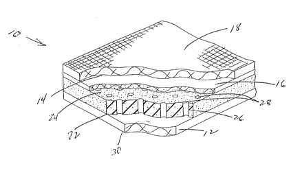
Fig. 1, a mlllti.cection composite material 10 useful in forming compression braces for
orthopedic support of a body part includes a user contacting fabric section 12 formed from
substantially hydrophobic fibers which has multidimensional stretch properties. Composite
10 10 also includes an outermost fabric section 14 formed from bonding two di.csimil~r
fabrics, a first fabric layer 16 formed from hydrophilic fibers having mlllti~lim~n~ional
stretch properties and a second fabric 18 formed from hydrophobic fibers. Composite 10
further includes an intermediate section 20 which has a first surface 22 and a second
surface 24. Intermediate section 20 is formed from a closed cell foam 26 having a
multiplicity of perforations 28 therethrough from first surface 22 to second surface 24.
Intermediate section 20 has mlllti(limensional elastic properties sufficient for providing
col,lpressi~fe strain useful for support of a body part. Intermediate section 20 has first
surface 22 bonded to a surface 30 of user contacting section 12 and second surface 24
bonded to first fabric layer 16. Intermediate section first surface 22 may be bonded to
20 surface 30 of the user cont~cting section and intermediate section second surface 24 may
be bonded to first fabric layer 16 by a suitable adhesive, either solvent based or hot melt,
by ultrasonic welding, solvent welding or any other technique available to the art of
bonding fabric to foam. Preferably intermediate section first surface 22 is bonded to
-6-
2129562 P-2890
surface 30 and intermediate section second surface 24 is bonded to first fabric layer 16 by
a solvent based adhesive.
Suitable hydrophilic fibers for forming user cont~cting section 12 include, but are
not limited to nylon, polyester, polyl,lo~,ylene, blends of nylon, polyester and5 polypropylene and the like. Suitable fabrics for user contacting section 12 may be formed
by weaving, knitting, and nonwoven techniques such as spun bonding, air laying and the
like. A preferred fabric for user contacting section 12 is circularly knit nylon formed from
sixty to eighty denier, twenty to thirty filament nylon yarn.
Intermediate section 20 may be formed from closed cell foams such as
10 polyurethane, natural rubber, polychloroprene and the like. A preferred foam is
polychloroprene such as that made by foaming duPont Neoprene GWTM (E.I. duPont,
Wilm. DE) to a density between about 0.15 to about 0.20 grams per cubic centimeter.
The foam is cut into sheets having a thickness between about 2.5 millimeters (mm) to
about 40mm so that the foam has a tensile strength in the machine direction of between
about 25 to about 45 kilograms/square centimeter (kg/cm2) at between about 150 to
about 350 percent elongation. The plerelled foam has an ~lltim~te tensile strength in the
cross-machine direction between about 15 to about 45 kg/cm2 at between about 200 to
about 500 percent elongation. Foams may be formed from polymer chips by several
methods. Any of the standard methods for expanding or blowing the substantially solid
20 polychloroprene chips into a stable closed cell foam may be used in the present invention.
Standard methods generally all involve generation of the foam with movement to curing or
stabilization in some fashion. This process generally provides a directionality or "grain" to
the product produced. The machine direction is defined, similarly to a paper roll from a
paper machine or a knit fabric from a knitting machine, as the direction of the flow, and
P-2890
~ ~ ~9S~
the cross-machine direction is defined as being perpendicular to the flow. A foam having
the prefelled density and strength properties, will, when forrned into a brace which is
correctly sized for the user's physical stature provide a compressive strain in the range of
about 20 to about 80mm of mercury (mm Hg) which is suitable for providing orthopedic
5 support to a body part.
The multiplicity of perforations 28 in the foam may occupy any amount of the
volume of the foam which does not substantially reduce the density of the foam, hence its
ability to provide colllpress;~e support. Preferably, perforations 28 occupy between about
... .
three to about ten percent of the volume of the foam and, given the ranges of the tensile
10 strength and elongation values for the plefelled polychloroprene foam, do not adversely
effect the foam's ability to provide the required compressive stress.
A~lvt;l lillg to Figs. 2-6, a conlpression brace for a body part for example in Fig. 2,
an anlde brace 29 includes a substantially tubular structure 31 which has a passageway 32
ther~lhrough open from a first end 34 to a second end 36. Tubular structure 31 is formed
lS from a sheet 38 of composite 10 as is shown in Fig. 3. For the case shown in Fig. 2 when
structure 31 is intended as an ankle brace, sheet 3 8 is cut to a shape
having an opening 44 for the heel portion of a foot and edges 46 and 48. Cut shape 40 is
fommed into tubular structure 31 by joining edges 46 and 48. Edges 46 and 48 may be
joined by adhesive bonding, ultrasonic welding, heat coll~pression, solvent bonding,
20 sewing, merh~nical f~tening and the like. A plt:Ç~ d embodiment of the anlcle brace, as
is shown in Fig. 2, has a seam 50 fommed as a butt joint 52 joined by sewing.
A brace may be produced from the shape cut to the design as a single piece of
material of the invention to fomm the subst~nti~tly tubular structure. Altematively, the
brace may be constructed of a plurality of pieces of the material of the invention joined at
P-2890
2129562
edges to form the subst~nti~lly tubular structure. In the case where the brace is
constructed from the plurality of pieces, account may be taken of the di~rel.~ial stretch
properties between the machine and cross-machine directions of the composite material of
the invention. As the design is laid out to form the shape for cutting, the placement of the
S design on the sheet may be set to favor the machine, cross-m~chine or somewhere
between the machine or cross-machine direction depending on where the particular shape
will be used in forming the substantially tubular shape. This utilization of the differential
stretch properties enables formation of a compression brace with control of the placement
of co~llples~i~re stress about the body part supported by the brace.
Using Figs. 2 and 3 as a model, showing the compression brace for the ankle, a
similar alternate embodiment of a brace 54 for the wrist is shown in Fig. 4, a brace 56 for
the thigh is shown in Fig. 5, a brace 58 for the elbow is shown in ~ig. 6 and a brace 60 for
the knee is shown in Fig. 7. In each of these cases, the subst~nti~lly tubular brace
structure is formed in the manner illustrated by Fig. 3 wherein sheet 38 is cut to shape 40
having design 42 applopliate for ankle brace 29. For the embodiments in Figs. 4-7,
specific designs are developed. Additionally, the brace may include a seam or seams to
provide the brace with specific shapes, particularly in the case of a brace formed from
more than one piece of the material of the present invention. As illustrated in Fig. 6,
Brace 58 has seams 62 and 64 to provide the design shaped for the elbow. Further, as can
be noted in Fig. 7, compression brace 60 for the knee may include an opening 66 to
expose at least a portion of the patella and seams 68 and 70 to provide the design shaped
for the knee. The designs are further refined to include small, medium, large and extra-
large sizes for accommodation of users having di~erenl physical stature.
g
2129~2 P-2890
Table I below shows the size ranges as the circumference in centimeters at the
measurement location for each brace.
Table I
Size
(Centimeters)
BracelMeasure Small Medium Lar~e Extra-lar~e
ment location
Elbow/Mid 22.8-25.425.5-28.6 28.7-31.8 31.9-37.4
Elbow
Thigh/Mid- 48.2-50.850.9-55.9 56.0-63.5 63.6-71.1
Thigh
Knee/Mid- 30.4-36.236.3-42.5 42.6-48.9 49.0-55.2
Knee
Ankle/Just 17.8-20.320.4-23.5 23.6-26.7 26.8-30.5
above Ankle
bone
-10-
2129562 P-2890
The wrist brace 54 is generally provided as a single size with provisions for anadjustable closure, preferably the closure is a multiple hooks and eyes fastener. The
provision of several sizes of each brace provides for a range of available braces with
5 subst~nti~lly similar col.lplessive stress for users having di~elenl physical stature.
Compression braces made lltili7.inp; composite material 10 are comparable to
braces as taught in United States Patent 4,832,010 to Lerman in providing compressive
support. The Lerman patent further teaches a brace having perforations to allow escape
of moisture which is emitted from the user's skin and which would be entrapped within a
brace as taught in United States Patent 4,084,056 to Hettick.
In the present invention, moisture emitted from the user's skin is passed through
the hydrophobic user contacting layer to the intermediate foam layer, whereupon it may
pass through the multiplicity of perforations to the outermost layer. The outermost layer,
by having a first hydrophilic layer bonded to the second surface of the foam, draws
15 emitted moisture away from perforations 28 onto second surface 24 of intermediate foam
layer 20 and spreads it for evaporation through the second hydrophobic fabric layer. By
drawing the emitted moisture away from the perforations and spreading it, the rate of
evaporation, which is dependent on the surface area of the water, is subst~nti~lly increased
and the rate of emitted moisture transport through the perforations is subst~nti~lly
20 enhanced. The first layer 16 further serves as a reservoir to prevent wet spots from
developing around perforations 28 which occupy only between about three to ten percent
of the volume of foam 20 thus facilitating evaporation of emitted moisture from
substantially all of the brace surface instead of only the area around the openings of the
perforations as would be the case in braces formed from material according to the te~ching
2t29S62 P-2890
of Lerrnan in United States Patent 4,832,010. The drawing away of emitted moisture
from the perforations with subsequent spreading of moisture across substantially the entire
surface 24 of intermediate layer 20 provides for substantially increased evaporation of
emitted water through second fabric layer 18 serving as the outside surface of the brace.
S The enhanced moisture transport allows a user of a closed cell foam support brace the
benefits of the support provided by the closed cell foam with comfort previously available
only with an elastic knit brace.