Language selection

Search

Patent 2129791 Summary

Third-party information liability

Some of the information on this Web page has been provided by external sources. The Government of Canada is not responsible for the accuracy, reliability or currency of the information supplied by external sources. Users wishing to rely upon this information should consult directly with the source of the information. Content provided by external sources is not subject to official languages, privacy and accessibility requirements.

Claims and Abstract availability

Any discrepancies in the text and image of the Claims and Abstract are due to differing posting times. Text of the Claims and Abstract are posted:

  • At the time the application is open to public inspection;
  • At the time of issue of the patent (grant).
(12) Patent Application: (11) CA 2129791
(54) English Title: ROLLER BEARING FOR A MOVABLE FLANGE
(54) French Title: ROULEMENT A ROULEAUX POUR JOUE MOBILE
Status: Deemed Abandoned and Beyond the Period of Reinstatement - Pending Response to Notice of Disregarded Communication
Bibliographic Data
(51) International Patent Classification (IPC):
  • F16H 07/02 (2006.01)
  • F16H 55/56 (2006.01)
(72) Inventors :
  • ROBERT, JEAN (Canada)
(73) Owners :
  • POWERBLOC IBC CANADA INC.
(71) Applicants :
  • POWERBLOC IBC CANADA INC. (Canada)
(74) Agent: ROBIC AGENCE PI S.E.C./ROBIC IP AGENCY LP
(74) Associate agent:
(45) Issued:
(22) Filed Date: 1994-08-09
(41) Open to Public Inspection: 1996-02-10
Examination requested: 2001-07-09
Availability of licence: N/A
Dedicated to the Public: N/A
(25) Language of filing: English

Patent Cooperation Treaty (PCT): No

(30) Application Priority Data: None

Abstracts

English Abstract


The roller bearing for use in a movable flange in a
variable-speed belt drive, the movable flange being movable
along a shaft coaxial therewith. The bearing comprises at
least three outer roller-tracks symmetrically disposed
around the shaft and longitudinal extending thereon; a
sleeve positioned around the shaft and coaxial therewith,
the sleeve being rigidly connected to the movable flange and
having inner roller-tracks respectively facing the outer
roller-tracks; at least two spaced-apart rollers rotatable
and snugly engaged between each outer roller-track and the
corresponding inner roller-track for supporting the sleeve
in a spaced-relationship around the shaft while allowing
axial movement of the sleeve along the shaft; and a bearing
cage mounted between the shaft and the sleeve for guiding
the rollers.


Claims

Note: Claims are shown in the official language in which they were submitted.

WHAT IS CLAIMED IS:
1. A roller bearing for a movable flange in a variable-
speed belt drive, the movable flange being movable along a
shaft coaxial therewith, the bearing comprising:
at least three outer roller-tracks symmetrically
disposed around the shaft and longitudinal
extending thereon;
a sleeve positioned around the shaft and coaxial
therewith, the sleeve being rigidly connected to
the movable flange and having inner roller-tracks
respectively facing the outer roller-tracks;
at least two spaced-apart rollers rotatable and snugly
engaged between each outer roller-track and the
corresponding inner roller-track for supporting
the sleeve in a spaced-relationship around the
shaft while allowing axial movement of the sleeve
along the shaft; and
a bearing cage mounted between the shaft and the sleeve
for guiding the rollers.
2. A bearing according to claim 1, wherein the number of
rollers in more than two, at least two juxtaposed rollers
between each outer roller-track and the corresponding inner
roller-track being proximate a region where a radial inward
force on the shaft is maximum.
3. A bearing according to claim 1, wherein the bearing
cage comprises a sleeve provided with a plurality of
apertures in which are set the rollers.
4. A bearing according to claim 3, wherein the bearing
cage is made of brass.
5. A bearing according to claim 3, wherein the bearing
cage is made of plastic.

6. A bearing according to claim 1, further comprising an
inner sleeve with axially extending rollers engaged with the
shaft may be provided around the shaft for allowing rotation
of the movable flange with respect of the shaft, the axial
rollers being engaged with the outer surface of the inner
sleeve.

Description

Note: Descriptions are shown in the official language in which they were submitted.


2129791
ROLLER BEARING FOR A MOVABLE FLANGE
FIELD OF THE INVENTION
S The present invention relates to a roller bearing for
a movable flange in a variable-speed belt drive adapted to
receive a trapezoidal belt by which power is transmitted
from the driving pulley to a driven pulley.
BACKGROUND OF THE INVENTION
Variable-speed belt drives are commonly used on small
vehicles such as snowmobiles, scooters or small cars. Such
belt drives substantially comprise a driving pulley, a
trapezoidal belt and a driven pulley. The driving pulley is
linked to an engine and the driven pulley is usually
mechanically connected to ground traction means, such as
wheels or tracks.
The main object of using a variable-speed belt drive is
to automatically change the winding diameter of the driving
and the driven pulleys in order to have a maximum torque at
low speeds and a reasonable engine rotation speed at high
speeds. The sides of the trapezoidal belt are, on each
pulley, gripped between two opposite flanges wherein one is
fixed and one is movable. At low speeds, the winding
diameter of the driving pulley is small and the winding
diameter of the driven pulley is maximum. As the rotation
speed of the driving pulley increases, sliding flyweights,
located between radially converging ramps facing each other,
are subjected to an increasing outward force pushing the
ramps away from each other. This axial thrust generated by
the flyweights is counterbalanced by biasing means, such as
a helicoidal spring mounted around the shaft of the driving
pulley, which biases the movable flange away from the fixed
flange. As the axial thrust pushes the movable flange
towards the fixed flange, the spring is further compressed.

" 212~791
The movement of the movable flange stops when the axial
thrust becomes substantially e~ual to the opposite biasing
force.
When the rotation speed of the engine decreases, the
winding diameter of the driving pulley decreases since the
movable flange of the driving pulley moves back away from
the fixed flange because the biasing force is then more
important than the axial thrust of the flyweights. The
movement of the movable flange stops when the axial thrust
becomes substantially equal to the opposite biasing force.
An example of a driving pulley in a variable-speed belt
drive is disclosed in U.S. patents nos. 3,659,470 and
5,052,981, and also in Canadian patent no. 1,212,559.
One of the drawbacks of conventional driving pulleys is
that the sliding movement of the movable flange is often
very difficult under in high loads because the friction may
be important in spite of the usual annular bearings. This
affects the reaction time of the pulleys and alters the
calibration thereof.
SUMMARY OF THE INVENTION
The object of the present invention is to provide a
roller bearing that is adapted to be used with the movable
flange in a variable-speed belt drive.
More particularly, the object of the present invention
is to provide a roller bearing for a movable flange in a
variable-speed belt drive, the movable flange being movable
along a shaft coaxial therewith, the bearing comprising:
at least three outer roller-tracks symmetrically
disposed around the shaft and longitudinal
extending thereon;
a sleeve positioned around the shaft and coaxial
therewith, the sleeve being rigidly connected to
the movable flange and having inner roller-tracks
respectively facing the outer roller-tracks;

2129791
at least two spaced-apart rollers rotatable and snugly
engaged between each outer roller-track and the
corresponding inner roller-track for supporting
the sleeve in a spaced-relationship around the
shaft while allowing axial movement of the sleeve
along the shaft; and
a bearing cage mounted between the shaft and the sleeve
for guiding the rollers.
A non restrictive description of a preferred embodiment
will now be given with reference to the appended drawings.
BRIEF DESCRIPTION OF THE DRAWINGS
FIG. lA is a cross-sectional view of a driving pulley
with a movable flange mounted on the shaft
according to the prior art.
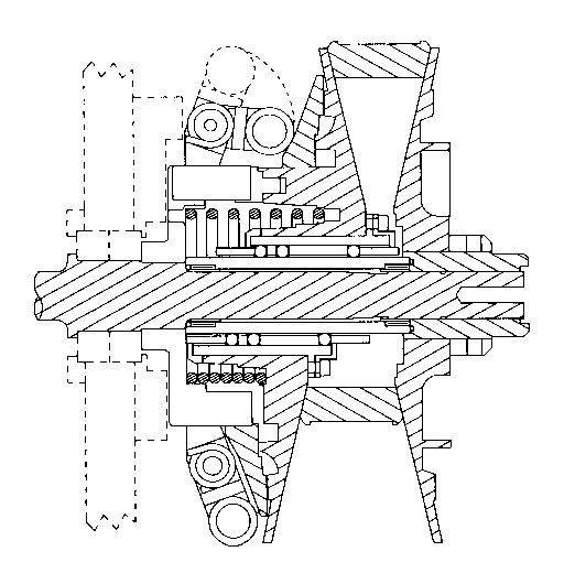
FIG. lB is a cross-sectional view of a driving pulley
with a movable flange mounted on the shaft with a
bearing according to the present invention.
FIG. 2 is a cross-sectional view of a bearing according
to the present invention.
FIG. 3 is a cross-sectional view of a sleeve according
to the present invention.
FIG. 4 is a cross-sectional view of a bearing cage
according to the present invention.
FIG. 5 is a cross-sectional view of an inner bearing
set around the shaft for allowing rotation of the
movable flange with respect of the shaft,
according to the present invention.
DESCRIPTION OF A PREFERRED EMBODIMENT
As shown in the figures, the roller bearing is for a
movable flange in a variable-speed belt drive, the movable
flange being movable along a shaft coaxial therewith. The
bearing comprises at least three outer roller-tracks

21297~1
symmetrically disposed around the shaft and longitudinal
extending thereon, a sleeve positioned around the shaft and
coaxial therewith, the sleeve being rigidly connected to the
movable flange and having inner roller-tracks respectively
facing the outer roller-tracks; at least two spaced-apart
rollers rotatable and snugly engaged between each outer
roller-track and the corresponding inner roller-track for
supporting the sleeve in a spaced-relationship around the
shaft while allowing axial movement of the sleeve along the
shaft; and a bearing cage mounted between the shaft and the
sleeve for guiding the rollers.
The number of rollers in more than two, at least two
juxtaposed rollers between each outer roller-track and the
corresponding inner roller-track being proximate a region
where a radial inward force on the shaft is maximum.
The bearing cage may comprise a sleeve provided with a
plurality of apertures in which are set the rollers.
The bearing cage may be made of brass or plastic.
Additionally, an inner sleeve with axially extending
rollers engaged with the shaft may be provided around the
shaft for allowing rotation of the movable flange with
respect of the shaft. The axial rollers are then engaged
with the outer surface of the inner sleeve.
Although a preferred embodiment of the invention has
been described in detail herein and illustrated in the
accompanying drawings, it is to be understood that the
invention is not limited to this precise embodiment and that
various changes and modifications may be effected therein
without departing from the scope or spirit of the invention.

Representative Drawing
A single figure which represents the drawing illustrating the invention.
Administrative Status

2024-08-01:As part of the Next Generation Patents (NGP) transition, the Canadian Patents Database (CPD) now contains a more detailed Event History, which replicates the Event Log of our new back-office solution.

Please note that "Inactive:" events refers to events no longer in use in our new back-office solution.

For a clearer understanding of the status of the application/patent presented on this page, the site Disclaimer , as well as the definitions for Patent , Event History , Maintenance Fee  and Payment History  should be consulted.

Event History

Description Date
Inactive: IPC from MCD 2006-03-11
Application Not Reinstated by Deadline 2004-08-09
Time Limit for Reversal Expired 2004-08-09
Deemed Abandoned - Failure to Respond to Maintenance Fee Notice 2003-08-11
Letter Sent 2001-08-16
Inactive: Application prosecuted on TS as of Log entry date 2001-08-16
Inactive: Status info is complete as of Log entry date 2001-08-16
Request for Examination Requirements Determined Compliant 2001-07-09
All Requirements for Examination Determined Compliant 2001-07-09
Application Published (Open to Public Inspection) 1996-02-10

Abandonment History

Abandonment Date Reason Reinstatement Date
2003-08-11

Maintenance Fee

The last payment was received on 2002-07-25

Note : If the full payment has not been received on or before the date indicated, a further fee may be required which may be one of the following

  • the reinstatement fee;
  • the late payment fee; or
  • additional fee to reverse deemed expiry.

Patent fees are adjusted on the 1st of January every year. The amounts above are the current amounts if received by December 31 of the current year.
Please refer to the CIPO Patent Fees web page to see all current fee amounts.

Fee History

Fee Type Anniversary Year Due Date Paid Date
MF (application, 3rd anniv.) - standard 03 1997-08-11 1997-07-10
MF (application, 4th anniv.) - standard 04 1998-08-10 1998-07-09
MF (application, 5th anniv.) - standard 05 1999-08-09 1999-07-16
MF (application, 6th anniv.) - standard 06 2000-08-09 2000-07-10
Request for examination - standard 2001-07-09
MF (application, 7th anniv.) - standard 07 2001-08-09 2001-07-26
MF (application, 8th anniv.) - standard 08 2002-08-09 2002-07-25
Owners on Record

Note: Records showing the ownership history in alphabetical order.

Current Owners on Record
POWERBLOC IBC CANADA INC.
Past Owners on Record
JEAN ROBERT
Past Owners that do not appear in the "Owners on Record" listing will appear in other documentation within the application.
Documents

To view selected files, please enter reCAPTCHA code :


To view images, click a link in the Document Description column. To download the documents, select one or more checkboxes in the first column and then click the "Download Selected in PDF format (Zip Archive)" or the "Download Selected as Single PDF" button.

List of published and non-published patent-specific documents on the CPD .

If you have any difficulty accessing content, you can call the Client Service Centre at 1-866-997-1936 or send them an e-mail at CIPO Client Service Centre.


Document
Description 
Date
(yyyy-mm-dd) 
Number of pages   Size of Image (KB) 
Representative drawing 1999-06-21 1 26
Abstract 1996-02-09 1 24
Description 1996-02-09 4 180
Claims 1996-02-09 2 47
Drawings 1996-02-09 4 83
Reminder - Request for Examination 2001-04-09 1 117
Acknowledgement of Request for Examination 2001-08-15 1 194
Courtesy - Abandonment Letter (Maintenance Fee) 2003-09-07 1 176
Fees 1999-07-15 1 30
Fees 1998-07-08 1 36
Fees 1997-07-09 1 38
Fees 2000-07-09 1 30
Fees 1996-07-09 1 36