Sélection de la langue

Search

Sommaire du brevet 2129791 

Énoncé de désistement de responsabilité concernant l'information provenant de tiers

Une partie des informations de ce site Web a été fournie par des sources externes. Le gouvernement du Canada n'assume aucune responsabilité concernant la précision, l'actualité ou la fiabilité des informations fournies par les sources externes. Les utilisateurs qui désirent employer cette information devraient consulter directement la source des informations. Le contenu fourni par les sources externes n'est pas assujetti aux exigences sur les langues officielles, la protection des renseignements personnels et l'accessibilité.

Disponibilité de l'Abrégé et des Revendications

L'apparition de différences dans le texte et l'image des Revendications et de l'Abrégé dépend du moment auquel le document est publié. Les textes des Revendications et de l'Abrégé sont affichés :

  • lorsque la demande peut être examinée par le public;
  • lorsque le brevet est émis (délivrance).
(12) Demande de brevet: (11) CA 2129791
(54) Titre français: ROULEMENT A ROULEAUX POUR JOUE MOBILE
(54) Titre anglais: ROLLER BEARING FOR A MOVABLE FLANGE
Statut: Réputée abandonnée et au-delà du délai pour le rétablissement - en attente de la réponse à l’avis de communication rejetée
Données bibliographiques
Abrégés

Abrégé anglais


The roller bearing for use in a movable flange in a
variable-speed belt drive, the movable flange being movable
along a shaft coaxial therewith. The bearing comprises at
least three outer roller-tracks symmetrically disposed
around the shaft and longitudinal extending thereon; a
sleeve positioned around the shaft and coaxial therewith,
the sleeve being rigidly connected to the movable flange and
having inner roller-tracks respectively facing the outer
roller-tracks; at least two spaced-apart rollers rotatable
and snugly engaged between each outer roller-track and the
corresponding inner roller-track for supporting the sleeve
in a spaced-relationship around the shaft while allowing
axial movement of the sleeve along the shaft; and a bearing
cage mounted between the shaft and the sleeve for guiding
the rollers.

Revendications

Note : Les revendications sont présentées dans la langue officielle dans laquelle elles ont été soumises.


WHAT IS CLAIMED IS:
1. A roller bearing for a movable flange in a variable-
speed belt drive, the movable flange being movable along a
shaft coaxial therewith, the bearing comprising:
at least three outer roller-tracks symmetrically
disposed around the shaft and longitudinal
extending thereon;
a sleeve positioned around the shaft and coaxial
therewith, the sleeve being rigidly connected to
the movable flange and having inner roller-tracks
respectively facing the outer roller-tracks;
at least two spaced-apart rollers rotatable and snugly
engaged between each outer roller-track and the
corresponding inner roller-track for supporting
the sleeve in a spaced-relationship around the
shaft while allowing axial movement of the sleeve
along the shaft; and
a bearing cage mounted between the shaft and the sleeve
for guiding the rollers.
2. A bearing according to claim 1, wherein the number of
rollers in more than two, at least two juxtaposed rollers
between each outer roller-track and the corresponding inner
roller-track being proximate a region where a radial inward
force on the shaft is maximum.
3. A bearing according to claim 1, wherein the bearing
cage comprises a sleeve provided with a plurality of
apertures in which are set the rollers.
4. A bearing according to claim 3, wherein the bearing
cage is made of brass.
5. A bearing according to claim 3, wherein the bearing
cage is made of plastic.

6. A bearing according to claim 1, further comprising an
inner sleeve with axially extending rollers engaged with the
shaft may be provided around the shaft for allowing rotation
of the movable flange with respect of the shaft, the axial
rollers being engaged with the outer surface of the inner
sleeve.

Description

Note : Les descriptions sont présentées dans la langue officielle dans laquelle elles ont été soumises.

2129791
ROLLER BEARING FOR A MOVABLE FLANGE
FIELD OF THE INVENTION
S The present invention relates to a roller bearing for
a movable flange in a variable-speed belt drive adapted to
receive a trapezoidal belt by which power is transmitted
from the driving pulley to a driven pulley.
BACKGROUND OF THE INVENTION
Variable-speed belt drives are commonly used on small
vehicles such as snowmobiles, scooters or small cars. Such
belt drives substantially comprise a driving pulley, a
trapezoidal belt and a driven pulley. The driving pulley is
linked to an engine and the driven pulley is usually
mechanically connected to ground traction means, such as
wheels or tracks.
The main object of using a variable-speed belt drive is
to automatically change the winding diameter of the driving
and the driven pulleys in order to have a maximum torque at
low speeds and a reasonable engine rotation speed at high
speeds. The sides of the trapezoidal belt are, on each
pulley, gripped between two opposite flanges wherein one is
fixed and one is movable. At low speeds, the winding
diameter of the driving pulley is small and the winding
diameter of the driven pulley is maximum. As the rotation
speed of the driving pulley increases, sliding flyweights,
located between radially converging ramps facing each other,
are subjected to an increasing outward force pushing the
ramps away from each other. This axial thrust generated by
the flyweights is counterbalanced by biasing means, such as
a helicoidal spring mounted around the shaft of the driving
pulley, which biases the movable flange away from the fixed
flange. As the axial thrust pushes the movable flange
towards the fixed flange, the spring is further compressed.

" 212~791
The movement of the movable flange stops when the axial
thrust becomes substantially e~ual to the opposite biasing
force.
When the rotation speed of the engine decreases, the
winding diameter of the driving pulley decreases since the
movable flange of the driving pulley moves back away from
the fixed flange because the biasing force is then more
important than the axial thrust of the flyweights. The
movement of the movable flange stops when the axial thrust
becomes substantially equal to the opposite biasing force.
An example of a driving pulley in a variable-speed belt
drive is disclosed in U.S. patents nos. 3,659,470 and
5,052,981, and also in Canadian patent no. 1,212,559.
One of the drawbacks of conventional driving pulleys is
that the sliding movement of the movable flange is often
very difficult under in high loads because the friction may
be important in spite of the usual annular bearings. This
affects the reaction time of the pulleys and alters the
calibration thereof.
SUMMARY OF THE INVENTION
The object of the present invention is to provide a
roller bearing that is adapted to be used with the movable
flange in a variable-speed belt drive.
More particularly, the object of the present invention
is to provide a roller bearing for a movable flange in a
variable-speed belt drive, the movable flange being movable
along a shaft coaxial therewith, the bearing comprising:
at least three outer roller-tracks symmetrically
disposed around the shaft and longitudinal
extending thereon;
a sleeve positioned around the shaft and coaxial
therewith, the sleeve being rigidly connected to
the movable flange and having inner roller-tracks
respectively facing the outer roller-tracks;

2129791
at least two spaced-apart rollers rotatable and snugly
engaged between each outer roller-track and the
corresponding inner roller-track for supporting
the sleeve in a spaced-relationship around the
shaft while allowing axial movement of the sleeve
along the shaft; and
a bearing cage mounted between the shaft and the sleeve
for guiding the rollers.
A non restrictive description of a preferred embodiment
will now be given with reference to the appended drawings.
BRIEF DESCRIPTION OF THE DRAWINGS
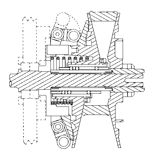
FIG. lA is a cross-sectional view of a driving pulley
with a movable flange mounted on the shaft
according to the prior art.
FIG. lB is a cross-sectional view of a driving pulley
with a movable flange mounted on the shaft with a
bearing according to the present invention.
FIG. 2 is a cross-sectional view of a bearing according
to the present invention.
FIG. 3 is a cross-sectional view of a sleeve according
to the present invention.
FIG. 4 is a cross-sectional view of a bearing cage
according to the present invention.
FIG. 5 is a cross-sectional view of an inner bearing
set around the shaft for allowing rotation of the
movable flange with respect of the shaft,
according to the present invention.
DESCRIPTION OF A PREFERRED EMBODIMENT
As shown in the figures, the roller bearing is for a
movable flange in a variable-speed belt drive, the movable
flange being movable along a shaft coaxial therewith. The
bearing comprises at least three outer roller-tracks

21297~1
symmetrically disposed around the shaft and longitudinal
extending thereon, a sleeve positioned around the shaft and
coaxial therewith, the sleeve being rigidly connected to the
movable flange and having inner roller-tracks respectively
facing the outer roller-tracks; at least two spaced-apart
rollers rotatable and snugly engaged between each outer
roller-track and the corresponding inner roller-track for
supporting the sleeve in a spaced-relationship around the
shaft while allowing axial movement of the sleeve along the
shaft; and a bearing cage mounted between the shaft and the
sleeve for guiding the rollers.
The number of rollers in more than two, at least two
juxtaposed rollers between each outer roller-track and the
corresponding inner roller-track being proximate a region
where a radial inward force on the shaft is maximum.
The bearing cage may comprise a sleeve provided with a
plurality of apertures in which are set the rollers.
The bearing cage may be made of brass or plastic.
Additionally, an inner sleeve with axially extending
rollers engaged with the shaft may be provided around the
shaft for allowing rotation of the movable flange with
respect of the shaft. The axial rollers are then engaged
with the outer surface of the inner sleeve.
Although a preferred embodiment of the invention has
been described in detail herein and illustrated in the
accompanying drawings, it is to be understood that the
invention is not limited to this precise embodiment and that
various changes and modifications may be effected therein
without departing from the scope or spirit of the invention.

Dessin représentatif
Une figure unique qui représente un dessin illustrant l'invention.
États administratifs

2024-08-01 : Dans le cadre de la transition vers les Brevets de nouvelle génération (BNG), la base de données sur les brevets canadiens (BDBC) contient désormais un Historique d'événement plus détaillé, qui reproduit le Journal des événements de notre nouvelle solution interne.

Veuillez noter que les événements débutant par « Inactive : » se réfèrent à des événements qui ne sont plus utilisés dans notre nouvelle solution interne.

Pour une meilleure compréhension de l'état de la demande ou brevet qui figure sur cette page, la rubrique Mise en garde , et les descriptions de Brevet , Historique d'événement , Taxes périodiques et Historique des paiements devraient être consultées.

Historique d'événement

Description Date
Inactive : CIB de MCD 2006-03-11
Demande non rétablie avant l'échéance 2004-08-09
Le délai pour l'annulation est expiré 2004-08-09
Réputée abandonnée - omission de répondre à un avis sur les taxes pour le maintien en état 2003-08-11
Lettre envoyée 2001-08-16
Inactive : Dem. traitée sur TS dès date d'ent. journal 2001-08-16
Inactive : Renseign. sur l'état - Complets dès date d'ent. journ. 2001-08-16
Exigences pour une requête d'examen - jugée conforme 2001-07-09
Toutes les exigences pour l'examen - jugée conforme 2001-07-09
Demande publiée (accessible au public) 1996-02-10

Historique d'abandonnement

Date d'abandonnement Raison Date de rétablissement
2003-08-11

Taxes périodiques

Le dernier paiement a été reçu le 2002-07-25

Avis : Si le paiement en totalité n'a pas été reçu au plus tard à la date indiquée, une taxe supplémentaire peut être imposée, soit une des taxes suivantes :

  • taxe de rétablissement ;
  • taxe pour paiement en souffrance ; ou
  • taxe additionnelle pour le renversement d'une péremption réputée.

Les taxes sur les brevets sont ajustées au 1er janvier de chaque année. Les montants ci-dessus sont les montants actuels s'ils sont reçus au plus tard le 31 décembre de l'année en cours.
Veuillez vous référer à la page web des taxes sur les brevets de l'OPIC pour voir tous les montants actuels des taxes.

Historique des taxes

Type de taxes Anniversaire Échéance Date payée
TM (demande, 3e anniv.) - générale 03 1997-08-11 1997-07-10
TM (demande, 4e anniv.) - générale 04 1998-08-10 1998-07-09
TM (demande, 5e anniv.) - générale 05 1999-08-09 1999-07-16
TM (demande, 6e anniv.) - générale 06 2000-08-09 2000-07-10
Requête d'examen - générale 2001-07-09
TM (demande, 7e anniv.) - générale 07 2001-08-09 2001-07-26
TM (demande, 8e anniv.) - générale 08 2002-08-09 2002-07-25
Titulaires au dossier

Les titulaires actuels et antérieures au dossier sont affichés en ordre alphabétique.

Titulaires actuels au dossier
POWERBLOC IBC CANADA INC.
Titulaires antérieures au dossier
JEAN ROBERT
Les propriétaires antérieurs qui ne figurent pas dans la liste des « Propriétaires au dossier » apparaîtront dans d'autres documents au dossier.
Documents

Pour visionner les fichiers sélectionnés, entrer le code reCAPTCHA :


Pour visualiser une image, cliquer sur un lien dans la colonne description du document. Pour télécharger l'image (les images), cliquer l'une ou plusieurs cases à cocher dans la première colonne et ensuite cliquer sur le bouton "Télécharger sélection en format PDF (archive Zip)" ou le bouton "Télécharger sélection (en un fichier PDF fusionné)".

Liste des documents de brevet publiés et non publiés sur la BDBC .

Si vous avez des difficultés à accéder au contenu, veuillez communiquer avec le Centre de services à la clientèle au 1-866-997-1936, ou envoyer un courriel au Centre de service à la clientèle de l'OPIC.


Description du
Document 
Date
(aaaa-mm-jj) 
Nombre de pages   Taille de l'image (Ko) 
Dessin représentatif 1999-06-21 1 26
Abrégé 1996-02-09 1 24
Description 1996-02-09 4 180
Revendications 1996-02-09 2 47
Dessins 1996-02-09 4 83
Rappel - requête d'examen 2001-04-09 1 117
Accusé de réception de la requête d'examen 2001-08-15 1 194
Courtoisie - Lettre d'abandon (taxe de maintien en état) 2003-09-07 1 176
Taxes 1999-07-15 1 30
Taxes 1998-07-08 1 36
Taxes 1997-07-09 1 38
Taxes 2000-07-09 1 30
Taxes 1996-07-09 1 36