Note: Descriptions are shown in the official language in which they were submitted.
: `
212~73
::~ ." :, .
,` . .
.
.. .
5' ' ~ ~ .
30345 :-
' `~! ( 911--4 6 0 )
,` ,, :~
,~ ' "~
:.
.s ",:'", '
ELECTRICAL CONNECq~OR INLET ASSEMBLY WITH ~ ;
. 1~,BREAR--AWAY MECHANISM FOR ELE:CTRIC VEHICIE
, :3
't"'
.' C~ .,
r" ~,. : . ...
,~,. ;' ~ ,.
Field o the Invention .
.~This invention relates to an electrical connector .
inlet assembly with a break-away mechanism for receiving a
plug or male eleckrical connector. The electrical
~:1 connector inlet assembly or receptacle mates with the plug .-~
;! or male electrical connector for electrically coupling a
. : first ~et of contacts in the plug with a second set of - : :
`:3~ 10contacts in the receptacle. In the event an excessive :
1 force occurs between the inlet assembly and plug, the :~
.~j break-away mechanism retracts the contacts of the inlet
assembly from the plug to release the plug from the inlet
~, caviky.
i.; .
;i~ 212~73 ~;
.,~
. .
- 2 -
BackgE~ound of the Invention
The number of automobiles being operated in the world
is continuing to increa~e. This increase in automobiles
ha~ significantly increased t]he worldwide air pollution
~ 5 problem. In order to control this air pollution problem
,`-~ from automobileF, many countries have begun to regulate ~he ;~
., exhauit ~missions from au~omobile~. In fact, the exhaust
, emissions standards are constantly becoming ~tricter each
year. For example, California regulators have recently
passed a law requiring 2% of all vehiclQs sold in
California to be ~zero-emissions" or electric powered by
1998. Failure tv meet the new emission ~tandard would ";
result in ~ignificant fines to au~omobile manufacturers
selling automobiles in California. A~cordingly, automobile
~q 15 manufacturer~' abllity to sell automobile~ in California
will be hurt if they do not produce an automobile with
~;;i zero-emissions.
~, In view of these increasingly stricter emi~sion - -~
;i!,l requ~rement , automobile manufacturers are beginning to
~ 20 develop electric powered vehicles. Accordingly, it will be
,~ nece~sary to provide the owners of the electric vehicles
with a safe and easy way of recharging their batteries.
Moreover, electric vehicles have a limited range of travel
before requiring their batteries to be recharged. Thus,
recharging stations will be needed which are conveniently
located and ea~y to operate in substantially the same
manner in which gas ~tations are currently available for
ga~ powered vehicles. ~`
One example of an electric vehicle and a recharging
station for recharging the batteries of electric vehicles
i8 disclosed in U.S. Patent No. 4,158,802 to Rose, II. The
electric vehicle and the racharging station disclosed in
i~ the patent i~sued to Rose, II have many drawbacks. For
instance, the contact surface of the vehicle i8 exposed to
.
~!~ ~ ~ .
,,
`~` ` 2~29~73 ~
.- :
. .
.... ..
, !
!i, 3
;.
,, '~
` !
,t,'~ the environment which can cause the electrical contact ;t
; surfaces of the vehicle to corrode. Also, the electrical
contact surfaces of the vehicle and the recharging ~tation
are exposed to the driver such that the driver of the
vehicle could sccidentally touch one of the electric
'>`jl! contacts and receive an electrical shock. Furthermore,
this recharging station would require all electric vehicles
to be manufactured within a c~rtain range of ~izes and
,~, shapes. .
r-!JJ 10 Accordingly, many att2mpts have been made to use
inductive power coupling~ to rechargQ the batteries of an
electric vehicle. Inductive power coupling~ transfer p~wer
~rom a power source to the vehicle by mean~ of a magnetic
~ield that extends through an air gap. ~owever~ these
inductive po~er couplings have certain disadvantages. For
example, research is currantly being conducted on the
harmful effects on humans of magnetic fields, ciuch as -~
created ~y inductive couplings. Moreover, existing
inductive power couplings are not capable of transferring
high amperage which is necessary to provide a fast charge ~ ~
~j to the vehicle~ 8 battery. ~ ;
~xample of inductive ~ower coupling~ are disclosed in
the following patents: U.S. patent 4,347,472 to Lemelson;
U.S. Patent ~,800,328 to Bolger et al; U.S. Patent
5,157,319 to Rlonte et al; Japanese patent application 53-
287607 to Matsuoka; German patent 23 30 255; and Japanese
patent application 58-69404 to Yamsda.
In view of the above, it i8 apparent that there exists
a need for an electrical connector assembly for
~i 30 transferring energy by conduction to electric vehicles from
i¦ electrical recharging stations which will overcome the
;;~ above probl~ns of the prior art, and which are safe and
co~venient to operate. This invention addresses this need
in the art along with other needs which will become
';
1 . . .
~: \
` ` 2~ 2~,73 ~
.
, .. ...
.,~ .....
.` .
.
~` apparent to those 6killed in ~he art once given this
disclosure.
!
Summary of the Invention
-~j 5Accordingly, a primary ob~ect of the present invention
i8 to provide an electri~al connector a~6embly, especially
for electric vehicles, which is safe and convenient to ~ ;
"
operate.
1 An ob~ect of the present invention i8 to provide an
`~ 10~lectrical connector assembly having one electrical
connector ~oupled to a recharging station and ano~her
electrical connector coupled to an electric car in which
the plug and the receptacle will disengage ~rom each other `~without damage thereto when an exces~ively high force is -~ -
1 15applied to the cable of the plug.
Another ob~ect of ths present invention i8 to provide -~
an electrical connector having its contacts covered or
concealed from the u~er to avoid accidental contact by the ~ ; ;
user.
20Another object of the present invention is to provide ~;~
an electrical connector a~sembly having a plug which can be
inserted into a receptacle with little or no force. ;~Another ob~ect of the present invention is to provide
an electrical connector ass~mhly having a plug with a fir~t
25set of contact~i and a receptacle with a second set of
contacts in which both sets of contacts remain covered
;~ ~ until after full in,3ertion of the plug into the receptacle.
~r Still another ob~ect of the present in~ention is to -
provido a weather-tight electrical connector assembly.
Another ob~ect of the present invention is to provide
an electrical inlet a#~embly having a weathershield or hood
.,
for covering the mating connector during recharging of the
'.';!~ vehicle.
: ~~.. .
! ~
,.i, i ~.. ~., ~'
i 1 :, ,.
:
.2gg73
}~
s
` ~
Pi~ -
Yet another object of the present invention is to
provide an electrical connector a~embly in which the
contact~ of the plug and the contacts of the receptacle
move in a direction transverse to the direction of
s insertion of the plug into the receptacle~
iX, Another ob~ect i8 to provide electrical connectors for
~-~ electric vehicles or electric recharging stativns which are
relatively inexpensive and sim~le to manufacture.
The foregoing ob~ect~ are basically attained by
providing, an electrical connector inlet assembly for
"~ recharging a battery of an electric vehicle, comprisings a
first housing with a mounting member for ri~idly coupling
the first housing to a structure of the veh~cle; a second
housing with an inlet cavity for receiving a mating
lS alectrical connector with a first ~et of electrical
contacts therein; a ~oint assembly movably coupling the
~i first housing to the second housing for limited relative
movement therebetween; a second set of electrical contac~s
movably coupled to the second hou3ing for movement between
a retracted position remote from the inlet cavity and an
extended position located within the inlet cavity for
electrically engaging the first set of electrical contacts
of the mating electrical connector; an actuation mechanism
op~ratively coupled to the second set of electrical
contact~ for moving the second set of electrical contacts
between the retracted position and the extended position;
~ and a break-away mechanism for disengaging the first ~et of
v electrical contacts of tha mating elactrical connector from
the second 8et of electrical contacts when coupled together
. 30 and after application of an excessively high force
.l therebetween, the break-away mechanism including a relea~e
~i mechanism for moving the second set of contacts from the
.. extended position to the retracted po~ition upon a
predetermined amount of relative movement between the fir~t
",
~`s
` ""';"
21~ 3 `
, ' ~ .
... .
.,.. ~. .
.i -... ..
~, 6 -
i`~ and second housings, and a trigger mechanism operatively
:: coupled between the first and second housings for sensing
relative movement between the first and second hou~ings and
operatively coupled to the release mechanism for activating
~i 5 the release mechani~m.
~' Other ob~ects, advantages and ~ali~nt features of the
~-' invention will become apparent from the following detailed
., description, which, taken in con~unction with the annexed
ill drawing~, discloseæ four preferred embodiments of the
invention.
~ S
Brief Dsscription of the Drawin~s
Referring to the drawings which form a part of this
original disclosure~
Figure 1 i8 a partial per~pective view of an
electrical connector assembly in accordance with a first
embodiment of the present invention and illustrated in
connection with an electric vehicle and an electric
~'; recharging ~tation;
Figure 2 i8 an anlarged, partial perspective view of
the electrical connector a~sembly illustrated in Figure 1
with certain parts broken away for clarity;
Figure 3 is a partial elevational view of an
electrical connector or plug just prior to full insertion
into an electrical connector inlet assembly or receptacle
which is shown in partial cro~s-section and with certain
parts removed for clarity;
~'`1 Figure 4 i~ a partial elevational view of the
electrical connector ~ust after full insertion into the
electrical connector inlet assembly which i8 shown in
partial crosl3-section and with certain parts removed for
clarity;
Figure 5 i~ z partial elevational view of the
electrical connector after full insertion into the
,~ Y ;~
' ' 'I :~
.. .. .
s.'l :
; ~2~73
.,.~
~j.. .. :
.... .
~i _ 7 _ :
. j
.~
... ..
electrical connector inlet a~;~embly, which is shown in
partial cross-~ection with certain parts removed for
.~! clarity and with the handle moved to the grab position;
:~; Figure 6 i8 a partial ele~ational view of the
eleckrical connector electri~ally coupled to the electrical
:~ connector inlet assembly, which i8 shown in partisl cross-
section with certain parts r~moved for clarity, and with
the weathershield or hood fully extended;
Figure 7 is an exploded perspective view of the
electrical connector or plug illustrated in Figures 1-6 in
~1 accordance with the present invention;
`~ Figure 8 is a schematic 8~ de elevational view of the
electrical connector or plug illustrated in Figures 1-7
;~ with a portion broken away to schematically ~how one of the
.~ 15 contacts;
F~gure 9 i8 a right side elevational view of the upper
half of the contact retainer body of the electrical
connector or plug illustrated in Figures 1-9;
Figure 10 i8 a rear elevational view of the upper half
:J 20 of the contact retainer body illu~trated in Figure 9;
'b~ Pigure 11 i~ a bottom plan view of the upper half of
the contact retainer body illustrated in Figures 9 and 10;
Figure 12 i~ a front elevational view of the upper
half of the co~tact retainer body illustrated in Figures 9-
Figure 13 i8 a front elevational view of the lower
half of the contact retainer body of the electrical
connector illustrated in Figures 1-8;
Figure :L4 i8 a top plan view of the lower half of the
contact reta:Lner body illustrated in Figure 13;
; Figure 15 i~ a rear elevational view of the lower half
~'`t of the contact retainer body illustrated in Figures 13-14;
Figure :L6 is a bottom plan view of the lower half of
the contact retainex body illustrated in Figures 13-15;
.''i! . ....
~ ':.; !
~i ` 212~7~
, " ': ~ . .
8 - ~ :
:
~,; ; ,
if~re 17 i8 a cross-~ect~lfLonal view of the lower half
i of the contact retainer body illustrated in Fig~res 13-16
taken along line 17-17 of Figuxe 13; ;~
Fif~ure 18 is a cross-sectional view of the contact ~:
cover of the electrical connec:tor or plug illu~trated in
~j Figures 1-8;
Figure 19 i~ a front elevational view of the
electrical connector inlet assf2mbfly or receptacle in
acfrordancfe with the present invention with cerSain parts
~ 10 removed ffofr clari.y; . ~.
~ Figure 20 i~ an exploded perspective view of selected
~ pf~ 8 of the electrif~ffal connfefctor lnlet asfse~fly or ~ ~
,i, receptacle illustxat2d in Fif~rfef 19; ;~.
Figure 21 iB a front elevational view of the ou~er `~
inlet housing of thf2 electrical co~ector inlet asse~f
illustrated in ~igures 19 and 20;
f~ Fif~re 22 i~ a ref~ elfevational view of the outer .;~
~fl inlet houf3ing of the electrical connector inlet assf~fly
~ illustrated in Fif~res 19-21; ~::
f;f; 20 fffif~re 23 is a longitudinal cross-sectional view of
the outer inlet housing of the electrical inlet assembly
f~(f illustrated in F~ f~res 19-22; -~ ;
'~¦ Figure 24 i8 a front eleva~ftional ~iew of the inner
inlet housing of the electrical connector inlet assfembfly `~
~i 1 25 illustratef-~f in Flgure~ 19 and 20;
~1 Figure 25 i8 a top plan view of the inner inlet ~ -
if -~
housing of the elefctrical connector inlet assemkffly
fl illustrated in Figures 19, 20 and 24; ~;
Figure 26 i8 a longitudinal cros~-~ectional view of ~ .
the inner in:Let housing of the electrical connector inlet
,"`~ assfembly shown in Fifgures 19, 20, 24 and 25; .
.f Figure ;2~ff i~ a lfefft side per~pective view of the cam
plate unit ~Df the electrical connector inlet asse~Dly
illustrated i.n Figures l9 and 20;
,.
.. ~ ! ~ '.
'``'`~ ''' ':
!;~
~~ :
`` 212~7~3 i
. :
., -
, . ~.
.,
, ., g . .
,..................................................................... .
- Figure 28 i8 a left side perspective view of the drive
,.. plate unit of the electrica:L connector inlet as~embly
i~ illustrated in Figures 19 and 20;
.. , Figure 29 is a left sicle perspective view of the
~i 5 actuation unit of the electrical connector inlet assembly
-'' illustrated in Fi~ures 19 and 20;
~-~ Figure 30 i8 a l~ft side perspecti~e view o~ the upper
`~ latch of the electrical connector inlet assembly
illustrated in Figures 19 and 20;
Figure 31 i8 a left side perspective vi~w of the lower
i~ latch of the electrical conne~tor inlet a~sembly
illustrated in Figures 19 and 20,
Figure 32 i8 a left side pexspe~tive view of the
release latch of the electrical connector inlet assembly
illustrated in Figures 19 and 20;
Figure 33 i8 a left side perBpective view of the inlet
contact cover of the electrical connector inlet a~sembly
~ illustrated in Figure 19;
P.j - Figure 34 iæ a left side elevational view of the
.~ zo contact bail of the contact assembly for the electrical
L~', connector inlet assembly;
. ~ Figure 35 i8 a rear elevational view of the contact
bail illustrated i~ Figure 34;
Figure 3b is a top plan ~iew of the contact bail
~i 1 2s illustrated in Figures 34 and 35;
Figure 37 i~ a left side elevational view of the
trigger support of the break-away assembly for the
electrical connector inlet assembly;
Figure 38 i8 a rear elevational view of the trigger
support of the breaX-away assembly illustrated in Figure 37
i.~. with a portion broken away for clarity;
Figure 39 i8 a top plan view of the trigger support of
the break-away assembly illustrated in Figures 37 and 38;
~; ~
~.,.
-- 212~3~73 `:
,. :
;i`, .
i , .
- 1 0
` :"
.,
Figure 40 LS a partial, exploded perspective view of
selected parts of the actuation assembly for the electrical
. ,. ; .
;:~ connector inlet assembly or receptacle;
<.~ Fi~ure 41 i~ a cross-sectional view taken along a
- 5 vertical plane extending thu~ough the center of the ~:
:. electrical connector inlet a88embly illu~trating the inlet :, :
. ..~,
contact assembly and break-away assembly; ~ :
Figure 42 i8 a cross-sectional Vi8W of the electrical - .
connector inlet as~mbly taken along a vertical plane
illustrating the release latch in the retracted po~ition;
Figure 43 i~ a cross-sectional view of the electrical
:l connector inlet as~embly taken along a vertical plane ; . :
illustrating the cam plate in the retracted position;
Figure 44 i8 a cro~s-sectional view of the electrical ..
, 15 connector inlet as~embly taken along a ver~ical plane ~-
illustrating the ~riVQ plate in the retracted position;
Figure 45 i8 a cro~s-~ectional view of the electrical
~ connector inlet assembly taken along a vertical plane
j illustrating the actuation plats in the retracted position;
.`1 20 Figure 46 i8 cros~-sectional view of the electric21
3 connector inlet ass~mbly taken along a vertical plane
illustrating the actuation plate ~n a ~rab position;
Figure 47 i8 a cross-~ectional view of the electrical
;,
connector inlet assembly taken along a vertical plane :~
illustrating the cam plate in an extended position; - ..
Figure 4B is a cross-sectional view of the electrical i;~
connector inlet assembly taken along a vertical plane
illustrating the drive pl~te in the extended position;
Figure 43 i8 a cross-sectional view of the electr~cal
3 30 connector inlet a~sembly taken along a vertical plane
illu~trating the actuation plate in the extended position;
~ Figure 50 i8 a cross-sectional view of the electrical
,J connector inlet assembly taken along a vartical plane
illustrating the cam plate and release latch in their
; : ~ ' . '` ' ':
: . ~
, .~,.,. :. ~
. ~ ~ . . .
2 ~ ~ 7 3
. .,
:'
. -- 1 1 ..
; break-away positions after a break-away force has been
~`~ applied to the electrical co~lector inlet a6sembly, but
prior to retrac~ion of the cam plate;
Figure 51 is a cross-sectional view of the electrical
~, 5 connector inlet assembly taken along a vertical plane
illustrating the cam plate in the retracted position after
i a break-away force ha~ been applied to the electrical
~I connector inlet assembly;
.~,, Figure 52 i~ a ~chematic view of the electrical
connector or plug shown in partial elevation and
,~:i illustrating the engagement with the upper latch prior to
;' movement of the upper latch by the electrical connector or
plug;
~-~ Figure 53 i8 a schematic view of the electrical
connector or plug shown in partial elevation and
illustra~ing the engagement of the upper latch with the
j'i lower latch after movement of the upper latch by the
electrical connector or plug;
Figure 54 i8 a ~chematic view of the electrical
~:~ 20 connector or plug ~hown in partial elevation and
illustrating the movement of uppex and lower latches after
full in~ertion of the electrical connector into the inlet
cavity and the actuation plate moved to a grab ~o~ition;
Figure 55 i8 a schematic view of the electrical
connector or plug shown in partial elevation~ and
illustrating the mo~ement of upper and lower latches upon
partial removal of the electrical connector or plug.from
the inlet cavity;
Figure 56 i8 a side per~pective view of an automatic
version of ~m elactric 1 connector inlet a~sembly in
accordance with a second embodiment of the present
invention;
Figure 57 i8 a partial side elevational view of the
automatic version of the electrical connector inlet
`' ~,' ,~.
`'
- 2~2~7~
, .
, . .
..... , ~ .
12
,l
" assembly illu~trated in Figure 56 with a portion of the
outer inle~ hou~ing broken away for clarity;
igure 58 is a perspecti~e view of the drive arm for
,;j the automatic version of the electrical connector inlet
assembly illustrated in Figures 56 and 57;
Figure 59 is an exploded perspective view o~ selected
parts of modified electrical connector inlet assembly
illustrated in Figures 1-55 in accordance with a third
.' embodiment of the present invention;
Figure 60 i8 a schematic cross-sectional ~iew of an
;~i electrical connector inlet as~embly in ~ccordance with the
b,'`'~ third embodiment of the prese~t inven$ion illustrated in
Figure 59;
, Figure 61 is a partial front ele~ational view of a
~ 15 vehicle with the slectrical connector inlet assembly of
.~ Fic3ures 59 and 60 mounted therein; and
Fic~ure 62 i8 a partial cross-~ectio~al view of an
automatic version of an electrical connector inlet as~embly
in accordance with a fourth embodLment o~ the present
invention taken along a ~ertical plane.
Detailed Description of ~he Drawinc~s
Referring initially to Figure~ 1 and 2, an electrical
~: connector assembly 10 especially desic3ned for use with an
eIectric car or vehicle 12 i8 illustrated in accordance
with the present invention, and includes a power source or
charging station 14 for dispensing electrical energy, a
plug or male electrical connector 16 electrically coupled
to power æousc:e 14 by an electrical and data/communicationæ
3V cable 18, a receptacle or ~emale electrical connector inlet
a883mbly 20 mounted in electric vehicle 12 for receiving
~ electrical energy from electrical connector 16, a battery
i 22 located i.n vehicle 12 and electrically coupled to
~ electrical co~nector inlet asæembly 20 for receiving
r~
21~73 :l
,
, ~,
,..
- 13 -
, i, .....
`.`~.~ electrical energy therefrom, ancl an on-board microproce~or
or computer 24 located ln vehicle 12 for transmitting and
,:~, receiving relevant data to and from power source 14 and to
and from electrical connector inlet a88embly 20 to control
:;5 the operation thereof.
While electrical connector 16 and electrical connector
~;~ inlet assembly 20 are illustrated in conjunction with an
~`- electric vehicle 12, it ~ill become apparen~ from this
disclo3ure that electrical connector 16 and electrical
connector inlet as~embly 20 can be u~ed in many other
electrical systems and applications. ~oreover, it will be
apparent to tho~e skilled in the art from this di~closure
that electrical co~nector 16 can be electrically coupled to
~æ~l battery 22 and on-board microprocessor 24 by cable 18, and
that electrical connector inlet a88embly 20 can be
electrically coupled to the recharging station 14.
t.J Po~er source or charging station 14 is preferably
connected to the local electrical utility company~ 8 power
line or to any other conventional source of electrical
energy. Charging station 14 can be mounted in practically
any location, including residential hou~es, apartment
buildings, gas ~tat~ons; parking garages, or even at the
~ide of a curb ~o that power can be readily available to
vehicls 12.
. 25 ' In residential applications, charging station 14 can
be electrically con~ected in a conventional maDner to a
cirauit braaker panel or power meter in a residential home
or apartment. ~lectrical connection~, breaker panels,
and~or power meter are all conventional and well known, and
thus they will not be discussed or illustrated in detail
herein.
,'1 In comme:rcial applications, charging station 14 can be
constructed to u8e ~imilar electronics as used in today~s
, automated gas station~. For example, charg~ng station 14
.~
'~
', '"' .
: 2~2~7~
`, .
~` .
. . ~ . . .
:~ - 14 -
. ~; . .
can be provided with a conventional power meter for
determining the amount of electrical energy disp2nsed, a
credit or debit card ~lot for payment of the dispen~ed
~' electrical en~rgy, and any other of the similar type of
~ 5 conveniences provided at automated ga~ ~tations. ~he
`~ electronics and circuit~ which can be used for operating
.~`i3~1 charging station 14 in commercial applications are
conventional and well known, i.e., ~imilar electrical
circuits are currently used to operate gas stat:Lon pumps,
and thus ~he electronics and circuit~ for charging station
14 will not be discu~sed or illustrated in detail herein.
~j hikewi~e, electric vehicle 12 with ba~tery 22 and
,'~,~.'','!~1 microproceæ~or 24 are all conventional and well known, andthu~ they will not be discussed or illustrated in detail.
As seen in Figure 7, cable 18 preferably includes four
elec~rical power conductors 26 and a comm~mications wire
28. Power conductors 26 are all 8ub8tantially identical ~o
each other, except that one of the conductors 26 is a
ground, and the other three conductors 26 are current
car~ying-conductors.
Each conductor 26 i~ a conventional conductor with a
conductive core and an insulating sheath covering the core.
Accordingly, conductors, such as conductor~ 26, are well
known, and thus will not be di~cu~sed or illustrated in
~ I 25 detail herein.
:~ Electrical Connector 16
.'~'.; A~ ~een in Figure 7, electrical coDnector 16 includes
~i (1) four terminal blocks 30 with cylindrical bores 32 and
cylindrical brush contscts 34, (2) a communications
connector or ~ata plug 36 with one or more communications
contacts 38, land (3~ an insulated housing 40 coupled to one
end of cable 18 for housing contacts 34 and 38.
,., Specifically, a terminal block 30 is fixedly coupled to one
'I,c
~1~
I"v
r ,:i~ `; ' ' .
,'"!;' s ~ . :
~ ~12~3~73
.
i-, - :,
~.~.i, . . .
~ 15 -
i,~;
end of each of the conductor~ .26l while the oth2r end of
i' each of conductors 26 is electrically eoupled to power
~ource 14. Each terminal block: 30 has a cylindrical bore
32 with a metallic, cylindrical, tubular brush Gontact 34
fixedly mounted within bore 32 and electrically coupled
conductive to the core of the associated conductor 26.
;;;~ Communications wira 28 i8 a conventional
:-! communication~ wire, and thus will not be discussed or
~l illustrated in detail herein. ~hile communications wire 28
0 i8 illustrated a~ a ~ingle conductor, it will be apparent
3 from thi~ disclosure tha~ ~ommunications wire 28 is
i~ preferably a data plug with a plurality of insulated
'~`!;,~ conductors which are each connected at one end to the
electronic circuitry of power source 14 and at the other
end to a plurality of contacts 38 contained in a
communications connector 36. Communic~tions connector or
data plug 36 i8 a conventional connector wi~h conventional
;~ electrical contact~ 38 electrically connected to the
in~ulated communications conductor~. For exampla,
~; 20 communications wire 28 and communications connector 36 can
~'~.i, be similar to a conv~ntional telephone wire and telephone
~acket which has a plurality of conductors and contact~
Accordingly, communications connector 36 as well as its
contacts 38 will not be illustrated or discus~ed in detail
herein.
,~ A~ seen in Figur~s 7 and 8, electrical connector 16 is
coupled to the end of cable 18 for housing the contacts 34
and 38 of c2~b1e 18, and for seleGtively covering and
exposing the contact~ 34 and 38 of cable 18.
A3 particularly seen in Figure 7, insulated housing 40
of electrical connector 16 is coupled to one end of cable
~; 18 in a water-tight manner, and includes a handle portion
42, a cable clamp 44 removably coupled to handle portion 42
~,. by two screws 46 for securing cable 18 thereto, a contact
. . !'
~ S~
, . I - ,
. . , - .
',' '
:i 2~2~,73
... .
. . .
.. .,,
~. .
' 1
~j, 16 ;
,
,,j,.. ~, ~ .
retainer body 48 for housing terminal blocks 30 and
~, communications connector 36, a contact cover 50 pivotally
coupled to contact retainer body 48 for selectively
concealing and exposing the contacts 34 and 38 of cable 18,
~i~; 5 a torsion spring 52 coupled between contact retainer body
48 and contact cover 50 for bialsing contact cover 50 to a
closed position covering contacts 34 and 38, and three
gaskets 54, 56 and 58 for protectin~ contactfi 34 and 38
from the weather or other contaminant6.
Handle portion 42 ha~ a mounting portion 60 with
three screw holes 62 for receiving ~crews 64 therethrough
for attachin~ the handle portion 42 to the contact retainer
body 48. The handle portion 42 al~o has a handle 66
extending rearwardly from mounting portion 60 and a cable
receiving cavity 68 for receiving conductors 26 and
`~ communications wire 28 therein. Preferably, handle portion
42 i8 molded as an integral, one-piecer unitary me~er from
a hard, rigid, non-conductive material ~uch as plastic.
Cable recei~ing c~vity 68 of electrical connector 16
2~ has a cable ~lamping ~urface 70 with a pair of threaded
holes ~not shown) for threadedly receiving screws 46 to
secure cable clamp 44 thereto. Specifically, conductors 26
and communications wire 28 are cl~mped between cable clamp
44 and cable clamping surface 70 for securing cable 18 to
electrical connector 16. Preferably, cable clamping
;~ sur~ac2 70 and ci~ble cli~mp 44 are both contoured with five
complementary rec~sses for individually sgueezing each of
the power conductors 26 and communication~ wire 28
therebetween iEor securely clamping ci~ble 18 to electrical
connector 16.
A~ ~een :in Figures 7-17, contact retainex body 48 of
~; electrical cor~ector 16 i~cludes an upper half or member 80
and a lower half or member 82 relea~i~bly coupled together
! ~ by four screw~ or fa~teners 84. Preferi~bly, both the upper
" ~ :
!.`.~
`. j ~ ~:
~ 212~73
, ~
,
... .
ii i, .
17 -
half 80 and the lower half 82 are molded as integral, one-
~ piece, unitary members from hard, rigid non-conductive
,-' material~ such as plaatic.
Referring to Figures 9-12, upper half 80 includes a
top wall 86, a front wall 87 extending from top wall 86, a
'~ pair of substantially identical side walls 88 extending
irom wall~ 86 and 87, a rear wall 89 extending between
l walls 86 and 88, and a hook 90 extending outwardly from the
-~ intersection o$ top wall 86 and front wall 87 for removably
coupling electrical connector 16 to electrical connèctor
inlet assembly 20 as discu~sed below.
Top wall 86 of upper half 80 ha~ four holes 91 with
;l one of the holes 91 being located at each of the corner~
for receiving ~cr~wa B4 therethrough. Extending downwardly
from top wall 86 are five positioning flanges 92 for
engaging terminal blocks 30 and communications connector
36. In other words, positioning flanges 92 maintain power
terminals 30 and communLcations connector 36 within lower
half 82 to prevent movement therein.
The rear wall 89 of upper half 80 has four power
conductor hole~ 93 for receiving power conductors 26
therethrough and one communicat:Lons wire hole 94 for
receiving communication~ wire 28 therethrough. ~ear wall
89 also include~ a threaded hole 95 for receiving one of
the screws 64 to rel2asably couple contact retainer body 48
to handle portion 42.
Referring to Figures 7 and 13-17, lower half 82 of
;~ contact retainer body 48 has a pair of substantially
identical side walls 100, a front wall 102, a rear wall 104
"h"~ 30 and a bottom wall 106. The ~ide walls 100 are each
~1 provided with a circular hole 108 for receiving a pivot pin
`~ 110 therethrough. The side walls 100 have upper portions
112 and lower portions 114 which form a part of a ledge 116
therebetween 130 that the upper portions 112 of the side
1.`'l ~ .
~.~ ~ ~ :
~,' ~ ~ ''"'.
,!
3 :
~`:.i ,
,~,.~ ~ ...
212~73
... . .
~,
,, i
,, - 18 -
.,~, i
;~ walls 100 are sized to be received between side wall~ 88 of
upper half 80~ In other w~rdst lower portions 114 are
spaced inwardly from upper portions 112 80 that side walls
88 of upper half 80 ~it on the ledge 116 of the lower half
S 82 when coupled together. The :lower portions 114 of side
~`, walls 100 are each provided with a notch 118 which engages
a portion of the electrical connector inlet assembly 20 as
discussed below. One or both of the lower portions 114 of
side walls 100 have a magnet 119 mounted therein for
~, 10 actlvating microprocessor 24 as discussed below in more
detail.
~i Front wall 102 of lower half 82 has a upper portion
120 and a lower portion 122 with a large front opening 124
communicating with the interior space of lower half 82.
Upper portion 120 is spaced inwardly from lower portion 122
:~ for forming a part of ledge 116. Opening 124 is sized to
,~ frictionally receive gasket 54 therein.
'; Rear wall 104 of lower half 82 has a pair of threaded
~`: openings 126 for receiving two of screws 64 therein. Rear
wall 104 also has five cutouts 127-131 for allowing
conductors 26 and communications wire 28 to e~ter the
îi interior ~pace of lower half 82 of contact retainer body
48.
Bottom wall 106 of lower ~alf 82 is recessed from the
bottom edges of side walls 100 80 as to form a cavi~y 132
i for receiving contact co~er 50 therein. Specifically,
bottom wall ln6 i8 substantially U-shaped 80 that cavity
} 132 i8 substantially U-shaped. ~ccordingly, contact cover
5 0 i8 received completely recessed within cavity 132.
Bottom wall 106 has a no~ch 133 for engaging torsion spring
52 for biasing contact cover 50 to a clo~ed position as
~,, discussed below.
1`.i' The lower half 82 of contact retainer body 48 further
~ includes four substantially identical dividers 134 which
1~." ~
,, ~ . ~, . . .
,, j ' '
j).~;~ .i;,
21 2 ~ ~ 7 3
.... .
,..;
.,~ ` 1 9 ~-
, . . . ~ .. .
'`, divide the interior of the lower half 82 of contact
retainer body 48 into five contact receiving cavities 135-
,~ 139. In particular~ dividers 134 are substantially
parallel with side walls 100 for maintaining terminal
blocks 30 and communications c:onnector 36 substantially
parallel and aligned with one another. The middle three
~ cavitie~ 136, 137 and 138 are subs~antially identical in
r~; size and ~hape, while end cA~ity 135 i8 slightly smaller
than middle cavitie~ 136, 137 and 138. End cavity 139 i~
even smaller than the remaining cavities for receiving the
communications connector 36 therein.
hedge 116 has ~our threaded bores 140 for threadedly
receiving screws 84 to ~ecure to upper half 80 of contact
retainer body 48 to lower half 82 of contact retainer body
48. Of cour~e, upper and lower halves 80 and 82 could be
permanently fastened together by an adhesive or other
fastening device.
As seen in Figures 7 and 18, contact cover 50 includes
a pair of substanti~lly identical side walls 172 with a
~ 20 curved cover plate 176 extending therebetween and a divider
;.. ,.~ plate 178 extending between side walls 172 so as to form a
pair of recesses 180 and 182.
Each of the side walls 172 has a pivot hole 184 for
~: receiving pivot pin liO therethrough for pivotally coupling
~ l 25 contact cover S0 to lower half 82 of contact retainer body
.;; 48. Pivot holes 184 are po~itioned to communicate with
: recess 180 80 that pivot pin 110 passe~ through recess 180.
~: Accordi~gly, :recess 180 of contact cover 50 is sized to
recei~e tor~ion spring 52 thereon. In particular, torsion
spring 52 is wrapped around pivot pin 110 for engaging both
contact co~er 50 and lower half 82 of contact retainer body
48 for biasing contact cover 50 to its closed position
~:~ ayainst retainer body 48.
r~
r,..~
'i''`'l ',-'''." " .,
:'",.j~ .
't.i'.~
`~ ` 212~7~
, . ~ ,
`' 20
,......
~, Cover 50 al80 has a pair of spaced notches 188 in the
front portion of curved cover plate 176 for pivoting
~, contact cover 50 between its open and closed positions by
electrical connector inlet asse~ly 20 as di~cussed below.
~, 5 A locking reces~ 189 is fo~med in the botto~ surface of
I cul~ed cover plate 176 for engag.ing a portion of electrical
,~i connector inlet as~2mbly 20 to retain electrical connector
~',;,~ 16 xelative to electrical connector inlet assembly 20.
~, Rece~ 182 of contact cover 50 i~ ~ized to encompass
the lower por~ions of cavities 135-139. Accordingly,
~:~3 contact cover 50 completely conceal~ the contact~ 34 and 38
`~ when in he clo~ed position.
As seen i~ Figur~P 7, torsion spring 52 is a
onventional torsion spring constructed of resilient wire
,-1 15 which ls helically wrapped. Tor~ion ~pring 52 has a first ~ -
end 190~ an intermedlate tab 192 and a second end 194.
; First and second ends 190 and 194 engage divider plate 178
1 of contact covar 50, while the tab portion 192 engage~
!,'~`~.' notch 133 ormed in bottom wall 108 of lower half 82 of
contact retainer body 48.
A~ seen in Figure 7, gaskets 54, 56 and 58 are
co~ventional gaskets made of resilient material such as
foam or rubber. ~asket 54 i8 curved and has five circular
openings (not shown) therethrough for xeceiving the --
contacts of the ele~trical connector inlet as~embly 20
therethrough a~ diseussed below.
~' Gasket 56 is substantially circular in cross-section
and form~ a rectangular ring which i8 frictionally retained ';',.~r~
around bottom wall 106 within cavity 132 of lower half 82
~`1 30 of retainer body 48 ~o that the upper e~ges of side walls
172 as well a~ the upper edge of the curve cover plate 176
engages ga~ket 56 to ensure that the contact remained
sealed when the cover 50 i~ in the closed position.
'`` ~1 :~ - .
,., ~ .
,. ~j . . .
212~7~
. . ,
:., . , :. --
~.
! . - 21
Gasket 58 is positioned between handle portion 42 and
contact retainer body 48 for sPaling the interface
therebetween. In par~icular, gasket 58 i8 ~ubstantially
rectangular with five circular openlng~ 198 for receiving
conductor~ 26 and communicationR wire 28 thersthrough.
Preferably, the holes 198 are sized to cause a friction fit
around the conductor~ 26 and communications wire 28 80 as
~`; to create a seal ~herebe~ween. The gs~ket 58 al~o has
three of holes 199 for receiving screws 64 therethrough.
"~, 10
f~ .~ Electrical Connector Inlet A~sembly 20
Reerring now to Figures 19~53, electrical connector
~ inlet assembly 20 includes (1) an ou~er stationary inlet
i~ housing 200 fixedly coupled to vehicle 12, ~2) an inner~ 15 movable inlet housing 202 movably coupled to outer inlet
i:i
'~J~ housing 200, (3) a universal ~oint assembly 204 for movably
~1 coupling i~ner inlet housing 202 to outer inlet housing 200, (4~ sn inlet contact assembly 206 movably coupled to
inner inlet housing 202, (5) an actuation assembly 208
movably coupled to inner inlet housing 202 for operating
~ inlet contact assembly 206, and (6) a break-away assembly
,`~3 210 ~or releasing electrical connector 16 from electrical
connector inlet assambly 20 upon application of an
~3 exces~ive force between electrical connector 16 and
electrical connector inlet a~sembly 20.
.,,-, , .
~! Outer Inlet Housina 200
Re~erring to Figures 20-23 and 40-50, outer inlet
housing 200 is preferably molded as an integral, one-piece,
unitary member from a hard, rigid non-conductive material ^ ~-
such as plastic. Outer inlet housing 200 has a top wall ~ i-
220, a pair of ~ubstantially identical ~ide walls 222
extending downwardly and substantially perpendicularly to
~¦ top wall 220, a bottom wall 226 extending between ~he lower
,, ~,;i .,
` 212~873
. . `
.
.~", : .
.
~, - 22 -
. .. ~, ':
..,
ends of side wall~ 222, a rear wall ~28 for mounting outer
inlet housing 200 to vehicle 12, and an open front 230 for
~i receiving inner movable inlet housing 202 therethrough.
~ii Accordingly, outer inlet housin~a 200 i8 rigidly coupled to
1 5 vehicle 12 and movably supports inner inlet housing 202 to
,.,
vehicle 12 as discussed below.
Top wall 220 of outer inlet hou~ing 200 has an
inverted U-~haped channel 234 and a pair of flat sections
236 and 238 extending outwardly from inverted V-shaped
channel 234 to side walls 222 of outer inlet housing 200.
Inverted ~-shaped channel 234 ha~ a pair of horizontally
aligned pivot hole~ 240 extending therethrough with their
longitudinal axis extending substantially perpendicular to
side walls 222. Pivot holes 240 are horizontally aligned
to receive a portion of universal ioint assembly 204 for
pivotally coupling inner inlet hou~ing 202 about a
horizontal aSxi~ between side walls 222 of outer inlet
~, r housing 200. ; --~
Side walls 222 of outer inlet housing 200 ars
preferably substantially flat planar msember~ which extend
substantially perpendicular to top wall 220 as well as
bottom wall 226 and rear wall 228. Side walls 222 are
~ubstantially parallel to each other, and spaced apart for
receiving inner inlet housing 202 therebetween.
Bottom wall 226 is a substantially flat wall with a
~¦ mounting hole 242 extending therethrough for mounting a `~
portion of break-away as~embly 210 thereto. Bottom wall
226 is substantially parallel to flat sections 236 and 238
of top wall 2:20 and spaced from top wall 220 for receiving
inner inlet hou~ing 202 therebetween. ~;
~i;, Rear wall 228 of outer inlet housing 200 has three i -
~i mounting holel3 244 for fixedly and rigidly securing outer
inlet housing 200 to vehicle 12. The rear wall 228 also
~3 has a conductor mounting ~ection 246 formed along it~
` 2129~73
.... . ;.
:, .
. -.,
.~ .
.~ 23
.. .:
. `
lower end for ~ecuring the electrical conductors of the
... ~ inlet contact a~6emb1y 206 thereto as discus~ed below in
more detail.
:~; Conductor mounting sect.ion 246 includes five
pa6sageways 251, a clamping plate 256 removably ?oupled to
~ rear wall 228 by four ~crews 258 to overly portion~ of
,',?1 passageways 251 and to secure the inlet conductors thereto.
::~ Passageways 251 are defined by four divider~ 261 a~ well as
by a first flange 266 with five cutouts 271 and a second
, 10 flange 276 with five cu~outs 277. Dividers 261 ex~end fr~m
¦ the rear wall 228 into the interior of outer inlet housing
200. Dividers 261 are tapered at their free ends and
provide in~ulation bet~een the inlet conductors.
. ., . ~ . .
;1 15 Inner Inlet Housinq 202 . -
Referring to Figures 24-26, inner inlet housing 202
includes a pair of substantially identical side walls 302,
a front contoured wall 304 extending between side walls
302, and a bo~tom wall 306 extending between iside walls
302. Preferably, inner inlet hou~ing 202 is molded as an . ;~:~
integral, one-piece, unitary member from a hard, ri.gid non~
conductive material such as plastic. Inner inlet housing
202 is movably coupled to outer inlet housing 200 by
universal ~oint a88embly 204 as di~cu~sed below.
Side walls 302 of inner inlet housing 202 are : ~:
substantially identical, and thus like reference numerals ~^
will be used to idantify the same parts on each of the side
walls 302. Each of the side walls 302 includes an :
outwardly extending mounting flange 310 with a pair of
upper mounting holes 311 for mounting a portion of
universal ~oint assembly 204 to inner inlet housing 202 via . ~:~
screw~ (not shown), and a lower mounting hole 313 for :~
.~ mounting a portion of braak-away a~sembly 210 to inner
inlet hou~ing 202. `~
', ~'~ . '
', ' - .`.
r,.~., :
'~ ~ ". ' .
:~: ` 2~g73 :~
:
24 - ~
''.:i , .:
~3
Each of the ~ide walls 302 further includes a ver~ical
control ~lot 314, an angled control slot 316, and a curved
.-, control 810t 318. Control ~lot:s 314, 316 and 318 control
the movement of the inlet con~act assembly 206 relative ~o
inner inlet housing 202 for expo~ing and extending ~he
~, inlet contacts a~ well as concealing and retracting the
.! inlet contact~.
~s :l .
~ Each of the side walls 302 is also provided with thrae
kr.-~ pivot pins 320, 322 and 324, two pivot holes 3~6 and 328,
., 10 a triangular clearance opening 330 and an arcuate clearance
~: opening 332 for coupling actuation a~semb~y 208 thereto as
discussed below in more detail. The in3ide ~urface of each
of the side walls 302 has a pair of rail~ 334 extending
parallel to angled control slot 316 for engaging and
~:! 15 controlling the movement of part of the inlet contact
,~ assembly 206 as discus~ed below.
Front wall 304 of inlet housing 202 includes an inlet
cavity 336 for receiving electrical connector 16 therein,
a ledge 338 for cooperating with hook 90 of electrical
connector 16, a pair of threaded holes 340 for securing the
front portion of universal joint assembly 204 thereto by
scr0ws 342.
Inlet cavity 336 i~ formed by a 8ub8tantially curved
wall 344 and a lower ~lat wall 346 which extend between
side walls 302 to form an inlet pocket with a rectangular
opening for receiving electrical connector 16 thereon.
Curved wall 344 includes an arcuate recess 348 positioned
ad~acent each of the side walls 302 of inner inlet housing
202. Recesses 348 are arcuate and aligned with curved
slotS 3ï8 fonned in side walls 302. Curved wall 344 al~o
includes five spaced contact openings 350 and five
reinforcing tubes 352 extending from the interior surface
of curved wall 344 and aligned with contact openings 350.
Lower wall 346 of inlet cavity 336 includes a pair of
"`,:''' ~':'
,
,;,,1 . .~1~;
,.. . .
2 ~ ~ ~ 3 : : ~
.. . .
.. ~;, ~
. .
. ,.
- 25 -
.,
~;j clearance openings 35~ which are aligned with recesses 348,
. and a locking pin 356 pro~ecting upwardly into inlet cavity
! 336 for engaging recess 189 formed in contact cover 50 of
~Z electrical connector 16. ~he clearance openings 354 permit
- 5 movement of the inlet contact ass~mbly 206, while locking
: pin 356 retains electrical connector 16 within inlet cavity
`.'l 336, as discussed below~
-, Bottom wall 306 of inner inlet housing 202 is
substantially planar and extends between side walls 302.
. ,~ .
Bottom wall 3D6 is provided with a ~emicircular cutout 356 .. :: -
~`~i for accommodating a part of $he break-away assembly 310 as :
discussed below. : ;.
Optionally, a sensor 358 can be mounted in a recess
formed in each of the side walls 302 of inner inlet housing
202 ad~acent inlet ~avity 336 as seen in Figure 42.
Sensors 358 are electrically coupled to microprocessor 24
to pro~ide various information to the microprocessor such -~
as the charging capability of electrical connector 16. ~ .-
In particular, sensors 358 are preferably reed
switches coupled to the side walls 302 of inner inlet
housing 202 ad~acent inlet cavity 336~ Sensors 358 are ~ d
activated by one or more of the magnet~ 119 on electrical
connector 16. Specifically, when electrical connector 16
is inserted into cavity 336 of electrical inlet connector
assembly 20, one or more of the magnets 119 will be
positioned ad~acent the reed switches or sensors 358 for
activating microprocessor 24. Accordingly, microprocessor ::
24 will not be actuated until the electrical connector 16
i8 correctly E~ositioned within inlet cavity 336. If the !"
electrical connector 16 is ab~ent from inlet cavity 336 or
not correctly positioned within the inlet cavity 336, the
il reed switches or ~ensors 358 will sense the absence or
.~ incorrect positioning of the electrical connector 16 to
r ' ~
'''1 ' . ' - :~'.,
;,, :.
r ~ `r:
!
.. j , i
`-- 212~73
~,.,
~, ..
... .
i - 26 - v
. .
prevent the contact pins 409 and the hood 510 from being
~i extended.
Reed switches or sensors 358 are conventional reed
i switches or sensors, and ~hus, will not be discussed or
-~ 5 disclosed in detail hers3in. Moreover, their electrical
connections with microprocessor 24 are conventional
electrical connections which will not be disclosed or
illustrated in detail herein. Basically, reed switches 358
preferably include a pair of spaced contacts which are
normally open, b~t closed when sub~ected to the magnetic
field of magnets 119. Accordin~ly, the closing of the
contacts of the reed ~witches 358 conveys information to
microprocessor 24 as discussed below.
Magnets 119 are mounted in side walls 100 of
electrical connector 16 so that they are positioned
ad~acent one or more of the sensor~ 358. Specifically, by
selecting one or more magnets 119, the reed switchs3s 358
can signal the microprocessor 24 to indicate the current
flow or amperage rating of the electrical connector 16.
In other words, ~y selecting the number of magnets
119, it is possible to indicate whether a 810w charge, fast
charge or normal charge i8 being supplied to vehicle 12 by
electrical connector 16. More specifically, if a magnet is
applied to the right ~ide wall 100 of electrical connector
16, then the corresponding sensor 358 will be activated by
the right side magnet to indicate a slow charge. If a
~l magnet i8 coupled to the left side wall lO0 of electrical
connector 16 with no magnet on the right side wall lO0 of
electrical connector 16, then electrical connector 16 will
acti~ate the left side sensor 358 of the inlet assembly 20
to indicate a normal charge to microprocessor 24. If a
magnet 119 i~ attached to both the right and left side
walls 100 of electrical connector 16, then both the right
~1
!
., . 1 - -` - .
'1 .
, . . . , :
~ ~12~73
. .
.
.
,, ~ . ... .
.
, . .
;,., - 27 -
,,.~ ,.
and left sensors 358 will be activated by the magnets ll9
~:~ to indicate a fast charge to the microprocessor 24.
In this manner, microprocessor 24 can adjust the
circuitry of vehicle 12 to acco~modate the amperage rating
',~ 5 or magnitude of power from the electrical connector 16. In
`, addition, microproces~or 24 can send a signal via
communications wire 28 to power source 14 to prevent any
current flow from electrical connector 16 to inlet assembly
`~ 20, if the electrical connector 16 i8 incompatible with the
circuitry of the vehicle 12.
Vniversal Joint Assembly ~04
~s seen in Figures 19, 20 and 41, universal ~oint
assembly 204 includes a front mounting bracket 360 coupled
to the front end of inner inlet housing 202 by screws 342,
a rear mounting bracket 362 coupled to the rear end of
inner inlet housing 202 by screws 312, a first pivot tube
366 extending between mounting brackets 360 and 362, a
se~ond pivot tube 368 rigidly coupled perpendicularly to
first pivot tube 366, a first pivot pin 370 rotatably
~; received within fir~t pivot tube 366, and a second pivot
pin 372 rotatably received within second pivot tube 368.
Front bracket 360 includes a pivot hole 374, a
rectangular opening 376 and a pair of mounting holes 378.
Pivot hole 374 couples the front end of inner inlet hossing
202 to first pivot pin 370 of universal ~oint assembly 204.
Rectangular opening 376 is sized to overly the opening of
inlet cavity 336 to allow electrical connector 16 to pass
therethrough as well as parts of actuation assembly 208.
~ounting holes 378 are sized to receive screws 342 for
~;~J;:~' securing front bracket 360 to inner inlet housing 202.
Rear br~-cket 362 is substantially U-shaped with a
,l~; centrally located pivot hole 380 located along its bight
portion, a ~irst pair of mounting holes 382 formed along
~ ;{ ~:-. ...
': '
.~ ,
, ::
` - -
2 ~ 7 3
",
,`,i :
~ , ~
. .`, .
., - 28 -
.-
:: .
' one of the leg portions, and a second pair of mounting
,~ holes 384 along the other leg portion. Pivot hole 380
~'" pivotally couples the rear porti,on of inner inlet housing
202 to outer inlet housing 200 via pivot pin 370 of
universal joint assembly 204. ~[ounting hole~ 382 and 384
receive screws 312 for securing rear bracket 362 to side
walls 302 of inner inlet housing 202 via threading screws
312 into mounting holes 311 formed in inner inlet housing
202.
First pivot tube 366 extends substantially
perpendicularly to second pivot tube 368. First pivot tube
~l 366 receives first pivot pin 370 therein for rotational
movement, while second pivot tube 368 receives second pivot
pin 372 therein for rotational movement. First pivot pin
370 has a threaded bore 390 at each end for receiving a
ficrew 392 for fastening ~irst pivot pin 370 to front
i",,l bracket 360 and rear bracket 362 of inner inlet housing
202. Likewise~ second pivot pin 372 has a threaded bore
394 at each end for receiving one of the screws 396 to
secure pivot pin 372 to outer inlet housing 200.
Accordingly, universal ~oint assembly 204 allows inner
inlet housing 202 to rotate or move about the longitudinal
~', axes of pivot tube~ 366 and 368 relative to outer inlet
housing 200. The amount of movement between the two
~} 25 housings 200 and 202 i8 limited by the clearance between
,'''~ the two housings 200 and 202. Moreover, the break-away
~;1 assembly 210 al~o limits or prevents relative movement
~¦ between the tw~ ho-lsing 20 and 207 as discussed below.
".l, 30 Inlet Contact .ssembly 206
, As seen in Figures 20, 34-36 and 41, inlet contact
as~embly 206 includes five electrical inlet contacts 401-
405 movably coupled to inner inlet housing 202 by a movable
contact bail 406, and a movable contact cover assembly 408
~ ~!.',
",`i ~, '~; :'
!,:
'.,!
i ` . ~ .
`~ 2123~73
. ~
.,~
'. .; .
.~..................................................................... ..
..
;, .
1 - 29 ~
j. 1 , :
for exposing and concealing electrical contacts 401-405.
Inlet contact assembly 206 is operatively coupled to
actuation as~embly 208 such that actuation a88embly 208
j`jj~1; moves the inlet con~acts 401-40!5 as well as move~ contact
cover assembly 408 upon insertion of electrical connector
16 into inlet cavity 336.
~ ach of the electrical contacts 401~404 are
substantially identical except for their relative size.
Specifically, elec~rical contacts 402, 403 and 404 are
power contacts which are all substantially the ~ame size.
Electrical contact 401 i~ a ground contac~ which is
slightly smaller than the electrical p~wer contacts 402,
'3 403 and 404. Electrical contact 405 i8 a communications
connector with a plurality of contacts.
~ach of the electrical inlet contacts 401-405 includes
a contact pin 409 fixedly coupled to contact bail 406 for
r~ movement therewith, a conductive wire 410 coupled at one
~, end to one of the contact pins 409, and an end connector
~, 411 coupled to the other end of each conductive wire 410
i~ 20 for coupling one of the electrical conductors 412 of
vehicle 12 thereto, respectively. ~he communications
r,~;il contact 40S has a plurality of contacts for engaging
,~ communications connector 36, while the contact pins 409 of the remaining contacts 401-404 are ~olid, 3ingle contacts
for engaging contacts 34 of electrical connector 16. Of
course, communlcations contact 405 can have a single
contact, if desired.
Contact pins 409 of contacts 401-405 each have a main
body portion 413 for coupling conductive wire 410 thereto,
and a cylindrical pin portion 414 for electrically coupling
the electrical connector inlet assembly 20 to electrical
! connector 16. Nain body portion 413 ha~ an axially
extending threaded hole 415 for receiving a thumb screw
., i, .
2:~2~7.3
,~
..i,
,~,. .
~ - 30 ~
ji i J
416, and a transverse bore 417 communicating with hole 415
.', for receiving conductive wire 410.
Bore 417 is sized to recei1ve one of th~ ends of its
respective conductive wire 410 t:herein. Conducti~e wires
;l 5 410 are secured to main bod~ portions 413 of contact pins
409 by thumb screws 416. Specifically, thumb screws 416
are threaded into holes 415 until they engage conductive
wires 410 to crimp them wit~in bores 417. Thus, thumb
screw 416 electrically couples conductive wire 410 to main
body portion 413.
Cylindrical pin portion 414 of each contact pin 409 is
provided with an annular recess 421 for receiving a C-clip
423 to retain contact pin 409 within bail 406. Contact
pins 409 are constructed of any suitable conductive
material such as brass. ~ach of the contac~ pins 409 are
coupled to bail 406 for reciprocal movement therewith to
~l electrically engage and disengage contacts 34 and 38 of
electrical connector 16.
Each of the end connectors 411 includes a connector
pin 422, a pair of washers 424, and a pair of nuts 426.
;:~ One of the washers 424 and one of the nuts 426 are attached
on opposite ends of each of the connector pins 422.
~: Specifically, each of the connector pins 422 has a pair of
oppositely extending threaded ~hafts 428 and 430 with a
! 25 centrally located flange 432 positioned between shafts 428
and 430-
End connectors 411 are ~ixedly coupled within
passageways 251 by po~itioning one of the shafts 430 within
~^,.; each of the cutouts 271 and then sQcuring each of the end
., 30 connectors 411 therein ~ia one of the washers 424 and one
of the nuts 4;26. The other shafts 428 of end connectors
411 are fixedl~y coupled to conductors 416 in a conventional
manner via the! other one of the washers 424 and the other
~ one of the nuts 426.
.`',';il
~,
' ii ' ~ ' :'
,i~; .1 ., ~ : .
:', .
.; ::! .... .
21~73 ~'
,~ .
.. ..
.
` ' ' ~t'
~ .~
.!:', 3 1--
.~.9 ` .
~ Contact drive bail ~06 is a substantially rectangular
c~i~i member having five contact receiving cavities 434 for
;~ supporting main bodies ~13 of inLet contact pins 409. Each
of these cavities 434 has a rectangular cross-section with
a cutout 436 in one wall for receiving one of ~he
conductive wires 410 therein, and a bore 438 for xeceiving
pin portion 414 of one of the inlet contact pins 409
therein. Each of the cavities 434 receives one of the main ~ I
bodies 413 of electrical inlet contact pins 409~ while each
of the bores 438 receives one of the pin portions 414 of
-j electrical inlet co~tact pins 409.
Contact pins 409 are secured ~ithin cavities 434 by C-
1 clips 423 to prevent relative movement ~herebetween.
j Contac~ drive bail 406 al60 includes a slide member 440 and
i! 15 a pair of parallel rails 442 extending outwardly from each
; of its opposite longitudin~l ends for engaging rails 334 on
the interior surfaces of side walls 302 of inner inlet
housing 202 therein. In other words, rails 442 on each of
jJ the side walls 302 straddle one of the slide members 440 to ~ ~ `
form a pair of parallel slots for slidably receiving rails
j 334 of inlet housing 202. Each of the slide members 440
has a threaded hole ~45 for receiving a threaded pin 448.
Pins 448 are designed to slidably secure contact drive bail
406 to side walls 302 o inner inlet housing 202 via angled
! ~ontrol 810ts 316. Preferably, contact drive bail 406 is
;~ molded as an integral, one-piece unitary m~mber from a
ij hard, rigid no~-conductive material ~uch as plastic.
Contac~ Cover_Assembl~ 408
A8 seen in Figures 20, 33~ 41-44 and 47, contact cover
;~ sssembly 408 includes a curved contact cover 460, a pair of
~ drive linXs 462 and a connecting rod 464. Contact cover
`~ assembly 408 ils preferably controlled by actuation a6sembly
1 208 so that a ussr can expose or conceal the inlet contact ;;~
.,
:;
:.' i' ~
'~' , . .
~: 2~25~7~
,~ . . ...
" ,.
..i`~.,
`, `. ,
, .
i.i`, . . .~ .
~ 32 ~: :
!.,".~ ~ ' ~ ,
"'.'~'
::. pins 409 only after mating electrical connector 16 has been
` fully inserted into inlet cavity 336.
s, Contact covetr 460 is prefPrably molded as an integral
;`~ one-piece, unitary mem~ter from a hard, rigid non-conductive
5 material such as plastic. Contact cover 460 has a pair of
,~ arcuate slide arms 468 located at each of its ends, and a
pair of detentes 470 for engagins notches 188 formed in
contact cover 50 of electrical connector 16 to exptose
contacts 34 and 38 of electrical connector 16 to inlet
contact pins 409. Each of the axms 468 ha~ a pivot hole
~, 472 for r~ceiving a threaded pin 473 which extends
outwardly therefrom for engaging curved control slots 318.
Specifically, pivot hol~s 472 extend through curved control
slots 318, and are then coupled to one of the ends of i~s
~`~i 15 respective c~ive link 462 via pins 473. The other ends of
~J?~ the drive links 462 are connected to the ends of connecting
rod 464 in a conventional manner such as by C-clips or
screws.
Connecting rod 464 is slidably received in vertical
control slots 314 of side walls 302 for 1iding movement
relative to inner inlet housing 202. Accordingly, movement
of connecting rod 464 causes drive link6 462 to reciprocate
contact cover 460 via pivot pins 472 sliding in curved
~I control slots 318. Preferably, connecting rod 464 has an
overlying sleeve 466 or engaging vertical control slots
314 to provide smooth sliding movQment of connecting rod
4S4 within control slots 314.
~ Arcuate slide arms 468 are positioned within curved
j~ rece6ses 348 of inlet cavity 336 of the inner inlet housing
202 for sliding movement therein. Accordingly, as
.' connecting rod 464 slides vertically within vertical
control slot 314, arcuate slide trms 468 of cover 460 is
~;~ reciproca~e within cuxved recesses 348 with a portion of
~: t",~
t;.
., t :
~ ? ? ? ~ ,V~ ?~
; -
2 ~ 2 ~ ~ 7 3 ~' '! '
:.
" " .
. ~ .
~ _ 33 _
~'
arms 468 moving through clearance openings 354 ormed in
~, lower wall 346 of inle~ cavity 336.
."
, i ~
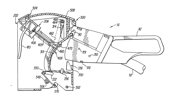
Actuation Assembly 208 --
Referring to Figures 20, 27-29 and 40-53, actuation
assembly 208 includes (1~ an actuation unit 500 pivotally
coupled to inner inlet housing 202 by a first pivot rod ~ :~
502, (2) a drive unit 504 pivotally coupled to imler inlet
housing 202 via a ~econd pivot rod S06, (3) a cam unit 508
.i~ 10 pivotally coupled to innPr inlet housi~g 202 via second :.
pivot rod 506, (4) a hood or weathershield 510 fixedly
coupled to cam unit 508 for movemen~ therewith, and (5) a
pair of connector control la$ch units 512 with one coupled
to each of the side walls 302 of inner inlet housing 202. -:.
Actuation unit 500 includes a handle 520, a pair of
`~ substantially identical side actuation plates 522 rigidly ; .
~;;,1 coupled to handle 520, a lower connecting plate 526
.~ extending between side actuation plates 522, and a torsion
`,t`~ spring 528 positioned on first pivot rod 502 for biasing
`~ 20 actuation unit 500 forwardly to a grab position or an
.~ extended position. `~
Handle 520 is preferably molded as a unitary, one-
piece, unitary member from a hard, rigid non-conductive
material such as plastic. ~andle 520 is preferably U-
shaped and fixedly coupled to each of the side actua~ion
`¦ plates 522 by screws 530 and pins 532. ;
: Side actuation plates 522 are substantially identical,
'. and each includes an inwardly extending drive pin 534 with .~. .
a steel bushing 536 thereon for engaging drive unit 504. :
~ 30 Each of the ~ide actuation plates 522 al~o includes a pivot
!~ hole 538 for receiving pivot rod 502, and a s~op member :
542. Preferably, side actuation plates 522 are integrally
formed with lower connecting plate 526, and are constructed
of a sheet material such as aluminum. -.:. :
, 1 :
, :
; .
, .! .
;,, ... ~ -
2~2~73
.~. .
..`i
,
.
,: ! ' '
1 Torsion spring S28 i5 a conventional torsion spring
which is positioned on pivot rod 502 with one end of the
torsion spring engaging lower connecting plate 526 and the
other end of torsion sprin~ engaS~ing a portion of the inner
':J 5 inlet housing 202 for normally biasing actuation unit 500
forwardly to a grab position or an extended position.
As se n in Figure 28, drive unit 504 ifi substantially
U-shaped and preferably made of sheet material such as
steel. Drive unit 504 includes a pair of ~ubstantially
identical side drive plates 544, an upper ~-shaped
connecting member 545, and a pair of tor~ion springs 548
positioned on the ends of pivot rod 506 for normally
biasing drive plates 544 forwardly to an extended position.
~'! Each of these drive plates 544 includes a pivot hole
548 for receiving pivot rod 506, an inwardly extending pin
550 for engaging one of the torsion springs 548 positioned
on pivot rod 506, an arcuate slot 552 for receiving the
outwardly extending pivot pin 322 of inner inlet housing
202, an L-shaped control ~lot 554 for receiving drive pin
534 with bushing 536 of actuation unit 500, and a latch
slot 556 for engagin~ connector control latch uni~ 512.
;~i Connecting member 546 is secured to each of the drive
plates 544 by rivets os other conventional fasteners. In
particular, the connector member 546 includes a bight
2S portion 558 extending between drive plates 544, and a pair
of legs 560. Each of the legs 560 is connected to one of
the respectlve drive plates 544, and includes a control
slot 562 for use with the motor driven version discussed
~;~ below.
As seen in Figure 27, cam unit 508 is substantially U~
i~ shaped and molded as an integral, one-piece, unitary member
from a hard, rigid non-conductive material such as plastic
or any other suitable material. Control unit 508 includes
a pair of substantially idsntical cam plates 570 connected
212~?,73
,
.~ .......................................................................... .
- 35 -
!: to opposite ends of hood 510. Cam plates 570 are
substantially parallel to each o~her and pivot together
about pivot rod 506.
3~ Each of the cam plates 570 includes (1) a pivot hole
572 for receiving pivot rod 506 therein, (2) a hole 574 for
~ receiving a connecting rod 576 therein, (3) a Pirst arcuate
;~. slot 578 with its arc positioned about the pivot hole 572
j J, for receiving pin 550 of one of the drive plates 544, (4)
a second arcuate slot 580 with its arc positioned around
pivot hole 572 for receiving pivot pin 324 of inner inlet
housing 202 therethrough, (5) a third arcuate slot 582 with
it~ arc positioned about the pivo~ hole 572 for engaging
release latch 650, (6) a first cam slot 584 for controlling
movement of the contac bail 406, and (7) a ~econd cam slot
586 for receiving the ends of connecting rod 464 to control
~ the movement of contact cover 460.
!,~ The pair of torsion springs 548 normally bias cam unit
:-........... 508 and hood 510 rearwardly for retracting the contact pins
~! 409 and for moving the contact cover 460 to conceal the
2~ contact pins 409 from inlet cavity 336. Specifically, one
end of each of the torsion springs 548 engages one of the
pins 550 of drive plates 544 and the other ends of each of
the torsion springs 548 engages the connecting rod 576.
Accordingly, torsion springs 548 causes a scissor action
between drive plates 544 and cam plates 570, i.e., drive
~, plates 544 are biased forwardly, while cam plates 570 are
~-. biased rearwardly by springs 548.
.~ ach of the connector latch units 512 is coupled ~o
t one of the ~ide wall~ 302 of inner inlet housing 202. As
seen in Figures 30 and 31, each of the connector latch
units 512 inc:ludes an upper connector latch S00 for
engaging elect:rical connector 16 to release actuation unit
500, a lower connector latch 602 for locking actuation unit
. 500 in the ret:racted position, and a pair of compression
'~
2~2~73
~ .
.,, .: .
~ - 36 - :
.. ' .
,. ~
~prings 604 and 606 for controlling the movement of latches
!~j'j 600 and 602. Upper latch 600 is movably coupled to inner
inlet housing 202 by pins 320 and 322 and biased in a
counterclockwise direction ~bout pin 320 by first
compression spring 604. Lowe!r latch 602 i8 pivotally
coupled to inner ~nlet housing Z!02 by pin 324 and biased in
a counterclockwise direction about pin 324 by second
compression spring 606.
As seen in Figure 30, upper latch 6no includes a first
slot 610 extending horizontally for receiving pin 320 of
inner inlet housing 202, a second 810t 612 with a U-~haped
; configuration for receiving pin 322 of inner inlet housing
~; 202, a first tab 614 extending through rectangular
j clearance opening 330 of inner inlet hou~ing 202 for
engaging electrical connector 16, a downwardly e~tending
abutment member 618 for engaging lower lat~h 602, and an
upwardly extending spring abutment 620 with a horizontally
extending tang 622 for engaging fir~t compression spring
As seen in Figure 31, lower latch 602 includes a pivot
hole 630 at one end for receiving pin 324 of inner inlet
~-;J
housing 202, and a latching tab 634 at the other end for
engaging stop 542 of actuation plate 522. Lower latch 602
also includes an upwardly extending abutment 634 for
engaging downwardly extending abutment 618 of upper latch
~i 600, and a downwardly ex~ending abutment 636 for engaging
second compression spring 606.
As seen in Figure3 52-55, when electrical connector 16
is in~erted into inlet cavity 336 of inner inlet housing
202, first tabs 614 of upper latches 600 will engage the
bottom edges of side walls 100 of electrical connector 16.
First tabs 614 of upper latches 600 will then slide along
the bottom ed/aes of side wall~ 100 of electrical connector
16 causing upper latches 600 to move downwardly against the
~! . ~
i~i ~ ,' .' ':
` ` ~12~73
,, .~.
.:.
. ., - .
- 37 -
i force of compression springs 604. Eventually, notches 118
,~ of electrical connector 16 will engage first tabs 614 of
upper latches 600 once electrical connector lfi is
.1 completely inserted into inlet cavity 336.
This downward movement of upper latches 600 by
.1 electrical connector 16 also causes lower latches 602 to
move downwardly since abutments 618 of upper latches S00
engage abl~tments 634 of lower latches 602. Abutments 618
. of upper latches 600 are maintained vertically aligned with
3;~ 10 abutments 634 of lower latches 602 since springs 604 hold
pins 322 in the forward legs of U-shaped slots 612.
Accordingly, as lower latches 60~ pivot downwardly about
;1 pivot pins 324, tabs 634 of lower latches 602 will
disengage from stops 542 of actuation plates 522, which in
turn allows the torsion spring 528 of actuation unit 500 to
move actuation plates 522 and handle 520 forwardly to a
grab position. In other words, actuation unit 500 will be
`!'i pivoted forward about pivot rod 502 by torsion spring 528
until pins 534 of actuation plates 522, which are
positioned within L-shaped slots 554 of clrive plates 544,
abut against the forward vertical edges of ~-shaped lot~
554 of drive plates 544.
Now, a user may grab the handle 520 to fur~her pivot
actuation unit 500 forwardly. This further movement of
actuation member 500 causes the drive unit 504 and the cam
unit 508 also to move fo~wardly which in turn causes the
inlet contact cover 460 to move upwardly and the contact
pins 409 to ~xtend within the inlet cavity 336.
Specifically, further forward movement of actuation unit
500 by the user also cau~es clrive unit 504 to move
forwardly since pins 534 of actuation plates 522 engage the
forward vertic:al edges of L-shaped 810t~ 554. Thus, drive
. unit 504 moves forwardly as plns 534 of actuation plates
522 move a~onq the vertical portions of L-shaped slots 554
` 2~2~73 ~
, :.,
,........................................................................ .. ~.
,"i ,
,`; , ` -
~ 38 -
. . .
. . - "
of drive plates 544. This is possible since actu~tion unit
500 has a different pivot axis from the pivot axis of drive
unit 504. Since rive unit 504 is coupled to cam unit 508
by release latch 650, cam unit 508 also moves forwardly
with actuation unit 500 and drive unit 504 upon forward
movement of actuation unit 500 from the grab position to
-~ the extending position.
.~ As seen in Figures 32 and 40, release latch 650 is
`~ releasably coupled to cam unit 508 and fixedly coupled to
drive unit 504 so that they all normally ~ove togetherO
However, if a break-away force occurs between outer inlet
~ hou~ing 200 and inner inlet housing 202 as discussed below,
then release latch 650 disengages from cam unit 508 to
allow cam unit 508 to pivot rearwardly by torsion springs
il 15 588. Drive unit 504 and release latch 650, on the other
~, hand, remain coupled together and biased forwardly by
torsion springs 548.
As electrical connector 16 is removed from inlet
cavity 336 of inner inlet housing 202, upper latches 600
- 20 will be pulled forward by electrical connector 16 to allow
lower latches 602 to move upwardly to lock actuation unit
500 in the retracted position. Specifically, the forward
movement of upper latches 600 occurs because first tabs 614
are positioned within notches 118 of electrical connector
16 and the outward movement of electrical connector 16 is
transmitted to upper latches 600. The forward movement of
upper latch2s 600 by electrical connector 16 disengages
abutments 618 of upper latches 600 from abutments 634 of
lower latches 602. New, compression springs 606 pivot
lower latches 602 upwardly about to pivot pin 324 so that
latching tabs 634 engage stops 542 of actuation plates 522.
This forward movement of upper latches 600 i8 permitted due
to pins 320 ri.ding along the horizontal slots 610 and pins
;~ 322 riding in the U-shaped slots 612. In other words, pins
,,, , :
21~g73
.
- 39 -
I 320 and 322 along with 810ts 610 and 612 control the
:~ movement of each of the upper latches 600. When upper
latches 600 are moved forward by electrical connector 16,
compression springs 6Q4 are compressad between a ledge of
inner inlet housing 202 and spring abutment 620. Once
electrical connector 16 i8 completely removed from inlet
cavity 336, tabs 614 di~engage notches 118 of electrical
connector 16, which in turn causes compression springs 604
~ to move upper latches 600 rearwardly to their original
.l 10 positions. As upper latches 600 move rearwardly, pins 322
move from the rearward le~s of the U-shaped 810~s 612 back
to the bottom of the bight portions of the U-shaped slots
612 beneath the forward legs of the U-shaped slot~ 612.
:~.; Release latch 650 is substantially ~-shaped, and
includes a bight port~on 652 and a pair of leg portions 654
extendin~ upwardly from bight portion 652. Preferably,
release latch 650 is constructed from a hard, rigid
material ~uch as steel or an~ other suitable material.
Release latch 650 is normally biased upwardly by a pair of
springs 655 which are attached at one of their ends to the
bight portion 652 and ~t their other ends to one of the
inner side walls 302 of inner inlet housing 202 as seen in
~;~ Figure 41.
Each of the leg portions 654 of release latch 650 is
~,` ~ 25 substantially identical, and includes a first pivot qlot
656 ~xtending vertically for receiving pivot rod 506
: therein, a second slot 658 extending vertical for receiving
one of the pins 550 of drive plates 544 therein, and an
outwardly extending flange 660 for raleasably coupling cam
unit 508 to c~ive unit 504. Each of the leg portions 654
are positionecl between one of the side walls 302 of inner
inlet housing 202 and one of the cam plates 570 of cam unit
508.
r,~i
'
.;.'1 .
` ;: 2 12 ~ ~ ~ 3
..~;~.
,..j
. - 40 -
.. ~ '
First pivot 810t 656 i~ a longitudinally extending
oblong hole so that release latch 650 can move
~ii longitudinally on pivot rod 506 as well as pivot about
pivot rod 506. Similarly, second slot 658 iis al~o a
;-: 5 longitudinally extending oblong hole for allowing
~ longitudinal movement of release latch 650 about pins 550
i~ of drive plates 544. Thus, release latch 650 can move
~ longitudinally along drive plates 544, but always pivots
i``~ with c~ive plates 544.
.;;, 10 Specifically, release latch 650 moves with drive unit
504, since the drive plates 544 and the leg portions 654
.~J all pivot about~pivot rod 502 and the leg portions 654 of
release latch 650 are secured to drive plates 544 by pins
550 of drive plates 544 as well as by flanges 660 of
release latch 650. Accordingly, as drive unit 504 moves
~ forwardly or rearwardly, the release latch 650 will also
;~ move forwardly or rearwardly with drive unit 504.
During normal use, release latch 650 is coupled to cam
unit 508, since flanges 660 of release latch 650 engage
shelves 583 of 810ts 582 formed in cam plates 570.
Accordingly, as drive unit 504 moves forwardly or
rearwardly by actuation unit 500/ cam unit 508 will also
move forwardly or rearwardly with drive unit 504 ~o long as
flanges 660 of release latch 650 engage shelves 583 of cam
, 25 plates 570. However, if a sufficient break-away force
occurs between the outer inlet housing 200 and the inner
inlet housing 202, then break-away assembly 210 will move
release latch 650 downwardly 80 that flanges 660 of release
latch 650 disengage shelves 583 of cam plates 570. Now,
flanges 660 of release latch 650 can freely slide within
slots 582 of c:am plates 570 so that torsion springs 588 can
mo~e cam plat;es 570 rearwardly. This rearward movement
causes the contact pin~ 409 to retract from electrical
' t
.,, '' .
~`'1
. ~ ' -,: .
, ~'.' ~ .
212~7~
::,
. j
?' .` .
'`1
- 41 -
1:',
~ connector 16 and to move inlet contact cover 460 to conceal
r~
the retracted contact pins 409.
Bight portion 652 has an upwardly extending flange 670
.1 with an upwardly extending slot 1;72 for receiving a portion
~ 5 of break-away assembly 210 to move release latch 650
/~ between a latched position coupling clrive unit 504 to cam
.j' unit 508 and an unlatch as di~cussed below.
~''
Break-away Assembly 210
Referring now to Figures 20, 41, 50 and 51, break-away
~ assembly 210 încludes (1~ a trigger support 700 rigidly
~3 coupled to inner inlet housing 202 by a pair of screws 702,
(2) a trigger lever 704 pivotally coupled to trlgger
support 700 by a pivot pin 706, (3) a compression spring
708 positioned within trigger ~upport 700 for biasing
trigger lever 704 in a counterclockwise direction, (4) a
ball bearing 710 positioned within trigger fiupport 700 for
engaging tric3ger lever 704, and (5) a ball bearing cup 711
located in support hole 242 of the outer inlet housing 200
for engaging ball bearing 710.
As best seen in Figures 37-39, trigger support 700
includes a rear wall 712 with a pair of mounting holes 714,
a front wall 716 extending substantially parallel to rear
wall 712 with a ~lot 717, a pair of side walls 718
extending perpendicularly between rear wall 712 and front
wall 716, and a bottom wall 720 for supporting trigger
lever 704 as well as ball bearing 710 and compression
spring 708.
In particular, bottom wall 720 ha~ a pair of
~ 30 intermediate support walls 722a and 722b extending upwardly
'~'`I'A~ from bottom wall 720 and between rear wall 712 and front
wall 716, ancl a pair of U-shaped walls 724a and 724b
extending upwa~rdly from bottom wall 720 and outwardly from
support walls 722a and 722b, respectively. Support walls
,i, .. .
212~7~ ~
, .
,~........................................................ . . . .
... .
~ 42
. .
722a and 722b form a channel 726 which is aligned with slot
.1 717 of front wall 716 for rec:eiving ~rigger lever 704
therein. Support walls 722a and 722b al80 form a pair of
cylinder~ 728 and 730 $or supporting ball bearing 710 and
compre~sion ~pring 708 ther~in~. Cylinder 728 is aligned
;, with a hole 732 extending ~hrough bottom wall 720 for
1~ slidably supporting ball bearing 710 therein. The cylinder
,~i, 730, on the other hand/ supports compre~sion ~pring 708
therein. Specifically~ the bottom end of the compres~ion
. 10 spring 708 e~gageB bo~tom wall 720, while the top end of
compression 6pring 708 engages a portion of trigger lev~r
704. The U-shaped wall~ 724a and 724b axe aligned with a
810t 734 formad in bottom wall 720 for receiving pivot pin
706 therein.
Trigg~r lever 704 i~ positioned within channel 726
~ormed by the pair of parallel 8upport walls 722a and 722b
which extend upwar~ly from bottom wall 720, while pivot pin
706 is positioned in 810t 734 which extends perpendicularly
to channel 726. Accordingly, trigger lever 704 i6
pivotally held within channel 726 by pivot pin 706 80 that
~: one end of trigger lever 704 i8 received within cylinder
728 for engaging ball bearing 710 and the other end of the
trigger lever 704 extends through cylinder 730 for engaging
compression spring 708 to bias trigger l~er 704 sbout
pivot pin 706 and against bight portion 652 of relea e
latch 650.
As seen in Figures 20, 41 and 50, trigger lever 704
has a first end 742, a second end 744/ a pivot hole 746,
and a spring engaging protrusion 748 located betw2en second
end 744 and p~vot hole 746 for engaging the upper end of
compression ~,pring 708. Trigger lever 704 i8i normally
biased in a counterclockwi6e direction by compression
spring 708 about pivot pin 706 80 that first end 742 of
~, trigger lever 706 pushes ball baaring 710 downwardly
~`i
`! i'
., ,,
";
2 ~ 7 3
.
,;~. '
.
4 3
against ball bearing cup 711 ancl ~econd end 744 of trigger
lever engages flange 670 for biasing release latch 650
~, upwardly. More specifically, the second end 744 of trigyer
~1, lever 704 is sized that the upper surface of $rigger lever
704 engages the upper end of slotR 672 of relea~e latch 650
and the lower surface of second end 744 of trigger le~er
i`1 704 engages bight portion 652 o release latch 650.
Accordingly, upward or downward movement of trigger lever
~i 704 will cause release latch 650 to move either upwardly or
downwardly therewith.
Compre~sion spring 708 and ball bearing 710 are
conventional, and thus, will not be di~cus~ed in detail.
Of course, it will be apparent to those ~Xilled in the art
from this disclosur~ that other b~asing ~echanisms and
sliding members can be u~ed in place of c~mpression spring
708 and ball b~aring 710 as needed or desired.
Ball baaring cup 711 i~ substantially circular in top
plan view and has a short circular shaft 750 extending
downwardly from its bottom ~urface for engaging support
~; 20 hola 242 of the outer inlet housing 200, and an upper
recess 752 for receiving ball bearing 710 which i~
supported in inner inlet housing 202 by trigger support
700.
Recss3 752 of ball bearing cup 711 includes a conical
portion 754 and a cylindrical portion 756 concentrically
~¦ arranged abou~ conical portion 754 such that in the normal
~"~ rest position ball bearing 710 8it8 within conical portion
754. Upon a force bein~ applied between outer inlet
housing 200 ~d inner inlet hou~ing 202, ball bearing 710
will ride out of conical portion 754 up into cylindrical
i portion 756 against the force of first end 742 of trigaer
!''"~ lever 704. Specifically, ball bearing 710 i8 normally held
within conical portion 754 by first end 742 of trigger
lever 704 due tG the counterclockwise force applied to
:~`, , '
, .; ~ ~ .
, p;
,,"1 . ~ ..... . .
.:
",~
,i$ ~ - -
:. 1 . .. .
.. ! `. ; '
"` 2 1 ~
,, :
. ~.................................................................... ..
:~ 44 :.
~i trigger lever 704 by compression spriny 708. When the -~
.~l break-away force i8 applied between outer inlet housing 200
and inner i~let housing 202, inner inlet housing ~02 along
with ball bearing 710 will move relative to outer inlet
hou~ing 200 and ball bearing cu~) 711 since univer~al ~oin~
88sembly 204 movably couples inner inle~ hou~ing 202 ~o
outer inlet housing 200. ~his relstive movement between
inner inlet hou~iing 202 and outer inlet housing 200 causas
the ball bearing 710 to ride up onto cylindrical portion
756 of ball bearing cup 711, which in turn cause~ trigger ~ :
lever 704 to pivot clockwise about pivot pin 7060 Trigger
lever 704 then moves relea~e latch 650 downw~rdly causing
flanges 660 of release latch 650 to disengage from the : -~
shelves 583 of the cam plate~ 570. Once release latch 650
disengages the shelve~ 583 of cam plate~ 570, the cam unit
508 with hood S10 will be bia~ied rearwardly by torRiion .
spring 528 to retract contact pins 409 and move contact r''- '
cover 460 to conceal contact pin~ 409.
,,~;j~,!ZO pperation of ~lectrical Çonnector Assembly 10
Referring now to Figures 3-6 and 40~55g electrical ` --o
connector 16 has its electrical contact~ 34 and 38 -
completely concealed by contact cover 50 p~ior to insertion `~
1~ o~ electrical co~nector 16 into electrical connector inlet
i~J! ~ 25 assembly 20, while the contact pin8 409 of electrical
. connector inlet as~embly 20 are completely concealad by
~: contact covor 460. Thus, inadvertent contact with either
~ of the electrical contac~s 34 and 38 of elec~rical
s~ connector 16 or the electrical contact pin~ 409 of
alectrical connector inlet a~sembly 20 by the user is
.Y prevented, as well as, the ingres~ of water or
, contaminants. ~
. In operation, electrical connector 16 i8 inserted into ~:inlet cavity 336 o~ electrical connectvr inlet assembly 20 ;
~`f .
,.,~ ~ .
jl ., . ~,
,;.~, .
.
~ 2~73
. '
~ .
: - ~5 -
:, ,
,
, ~
`.~. by first engaging hook 94 of ~slectrical connector 16 on
ledge 338 of inner i~let housing 202, and then ~wingin~
electricsl connector 16 downwardly into inlet cavity 336 of
electrical connector inlet assembly 20. Inlet cavity 336
i8 sized to receive electrical connector 16 therein with
little or no hand force by the user to in~ert electrical
connector lS into electrical connector inlet assembly io.
~oreover, the cavity 336 iB sized to allow contact cover 50
:l, of ~lectrical connector 16 to ba pivoted be~ween its closed
position and its open position for exposing contacts 34 and
38.
Once electrical connector 1~ i5 fully inserted into
inlet ¢avity 336 of inlet a~embly 29, side walls 100 of
il electrical connector 16 engage tab8 614 of upper latches
600 to release actuation unit 500 from the retracted
position to the grab position. A180, full insertion of
electrical connector 16 cause6 the notches 188 formed in
.. ;i contact cover 50 of electrical connector 16 to engage
,~ detentes 470 forme~ on contact cover 460 of inlet asse~bly
~-1 20 20. Specifically, dur~ng the downwiiqrd swinging of
~;~ electrical connector 16, the upper latches 600 are moved
downwardly by electrical connector 16 ~ince tab~ 614 are
positioned to engage the ~ide walls 100 of electrical
, connector 16 before elec~rical connector 16 is completely
swung downwardly to its rest position. This downward
movement of upper latche~ 600 causes lower latche~ 602 to
also mov~ dow~wardly since abutments 618 of upper la~ches
600 engage abutment 634 of lower latches 602. In other
words, upper latches 600 are pivoted downwardly against the
force of compIession springs 604 by electrical connector 16
~i and lower latches 602 are moved downwardly again6t the
~; force of compression ~prings 606 by upper latche6 600.
~his downward movement of lower latches 602 disengages tabs
632 from stop members 542 of actuation plates ~22 to allow
~ ,1!
'~` ~i . , .
,, . ,:
:j;J,
~` ~
2~2~7~3 ~
, ;. , ,
,.. ..
.. .
.. . . .
~!`. ' .' '., .' .
.,,'1 ' ',
, ?
:'.'.
~ - 46
.s ,
,,~ actuation unit 500 with handle 520 to rotate forwardly
about pivot rod 502 due to tor~;ion spring 5~. In other
words, lower latches 602 release actuation unit 500 ~o that
spring 528 rotates handle 520 to a grab positi~n for
5 permitting a u~er to make the electrical connection between
;~, electrical connector 16 and electrical connector inl~t
assembly 20.
~ow that the electrical connector 16 i~ fully inserted
into inlet ca~ity 336, the magn~t ox magnets ll9 will
activate sensor or ~en80r8 358. The ~ensor or sensor~ 358
. " ;~ ~
will then send a signal to microprocessor~ 24 to ~ndicate
the magnitude or level of the charging power being ~upplied
by electrical connector 16. The microproces~or 24 can then
ad~ust it8 circuitry to accept or re~ect the power or
energy from the power ~ource 14 once electrical connection
i8 accomplished. In other words, the microproce~sor 24 can
3 prevent the power ~ource from sending power to recharge the
bat~ery 22 if the current of the electr~cal connector 16 i8
incompatible with the vehicle'~ circuitry. Preferably, the
vehicle's circuitry i8 designed to ad~ust its input to
J accommodate the current level being supplied thereto.
~ow, the user grabs ha~dle 5~0 of actuation unit 500
and pu118 it forward about pivot rod 502 which in turn
~il causes drive unit 504, cam unit 508 and release latch 650
all to pivot forwardly along with hood 510. Specifically,
drive pin 534 with bushing 536 of actuat;on unit 500
engages the L-shaped 810t 554 of drive plates 544 for
~i moving drive unit 504 forwardly with actuation unit 500.
~rive unit 504 in turn moves cam unit 508 therewith ~ince
latching tab~ 660 of release latch 650 engage latch slots
556 of drive unit 504 and engage shelve~ 583 of cam unit
508. Accordingly, movement of the actuation unit 500 from
~;`l the grab po~ition to the e~tended position causes driYe
~ ,.................................................................... . .
' ~ , ",~ .~
;.,
,'~ 21h~73
~ 47 -
- , . . .
~, unit 504 as well as cam unit 508 and release latch 650 ~o ~:
also move forwardly to the extended position~
This mov~ment of cam unit SID8 drives the inlet contact : ~ .
.~ pins 409 from the~r retracted po8ition to t~eir extended .:
., 5 position ~o engage electrical contacts 34 and 38 of .;::
.~ electrical connector 160 A180, sLmultaneously the contact
- covers 50 and 460 axe moved out of the way fox exposing the
,..
respective contact~ 34 snd 38 of alectrical connector 16 ~o ~ -
:~ inlet contact pins 409 of inlet assembly 20. Specifically,
the ~orward movement of the cam pla~e~ 570 with ~ach of .
.~ their three control slot~ 314, 316 a~d 318 ~ontrol the
~-. movement of inlet contact aBsembly 206 for expo~ing and : :
.,i~ ,, ,
j extending the inlet contact pins 409 as well as for
i~ concealing and retracting the inlet contact pins 409. More
pecifically, the contact pins 409 are driven from the
retracted position~ to their forward or extended positions
:~`' 8inc9 contact drive bail 406 is slidably coupled within
i.~. angled control ~lots 316 and ~ngage first cam 510t8 584 of
cam plates 570. In other words, a~ cam plat~s 570 move
20 forward, the first cam 810t8 584 engage the pins of the
~; contact drive bail 406 to move tha contact drive bail 406
along angled control slots 316.
1 The contact cover~ 50 and 460 are al50 controlled by
the forward movement of cam plate~ 470 to expo~e and
25 conceal the contacts of the respective connector~ 16 and
20. In particular, the ends of connecting rod 464 are
po~itioned within second cam 810t8 586 SO that the forward
moYement of cam plate~ 570 cause8 the co~necting rod 464 to
move vertical:Ly downwardly within vertical control 810t8
314. This downward movement of connecting rod 464 in turn
CaU8eS drive linX8 462 to move contact cover 460 along
arcuate control ~lot~ 318 from a position concealing
contact pins 4L09 to a position e~posing contact pins 409.
Specifically, pivot pins 472 of contact cover 460 are
~, I . .
.~x l ,
`~i?
.~(, `j .
.~., `` , :. . ~
i :~ ., .
2 ~L 2 ~ 3
.
.,; , .
,.
- 48 - :
`.`!' '.:
.. ~,,~ . . .
connected to one of the ends of drive link8 462 and
~ positioned with arcua~e control slots 318. ~oreover, the
,~ arcuate ælide arms 468 of contact cover 460 are xeeeived in
.î the recesses 348 of the inlet cav~ty 336 to ensure smooth
5movement of contact cov~r 460 from a position concealing
~ contact pins 409 to a position exposing contact pins 409.
j~ This sliding movement of contact co~er 460 causes the
contact co~er 50 of electrical connector 16 to al~o pivot
y downwardly to expo~e contacts 34 and 38 of electrical
.. 10connector 16. In particular, detentes 470 of contact covex
460 are received ~n notches 188 of contact cover 50 80 that
.,,contact cover 460 and c~ntact cover 50 move togeth~r when
.icam unit 508 pivots about second pivot rod 506.
Now that the electrical contacts 34 and 38 of
electrical connector 16 are engaged with the contact pins
409 of the inlet as~e~bly 20, microprocessor 24 sends a
signal to powar source 14 via communications wire 28 to
indicate whether to ~tart charging the battery 22 of
vehicle 12 or to prevant charging of the battery 22 due to
incompatibility. Once the mlcroprocessox 24 initiates the
charging processes, the energy i8 ~hen supplied from power
source 14 to the battery 22 of ~ehicle 12. Upon full
charge of battery 22, mlcroprocessor 24 will send another
sign~l to the power source 14 via communications wire 28 to
;l 25 stop the flow of rurrent.
the event th~t the vehicle 12 is hit when being
~,recharged, the break-away assembly 210 will cause the inlet
,~contact a~sembly 205 to retract the inlet contact pins 409
,~from the contacts 34 and 38 of the electrical connector 16
~ 30 as well as cause the inlet contact cover 460 to move from
`.,its position e.xposing the contact pins 409 to its retracted
~,position concealing contact pins 4Q9 and the contact cover
50 to mova from its open position expo~ing contacts 34 and
~l38 to it8 clo,~ed position concealing contacts 34 and 38.
.-~ ~ .
"'i ;`~' '' ~
`~1 ,~ .. . "
,:,.'~ , .
,.. ' .
., ~
` ~$1 _ 4 9
~ :; ..................................................................... .
1 Specifically, any relative movement between outer inlet
hou~ing 20 and inner inlet housing 202 will cau e break-
away assembly 210 to cause release latch 650 to disengage
shelves 583 of the cam plates 57~ which in turn allows
~; 5 torsion springs 588 to rotate cam plates 570 rearwardly.
This rearward movement o~ cam plates 570 by torsion ~pring
588 causes the contact pins 409 to retract and the lnlet
`~ cover 460 to move from a po~ition exposing the contact to
a po~ition concealin~ the contact pins 409 afi discussed
,~, 10 above in more detail~ In other word~, cam slots 584 and
! 586 engages the ends of contact dsive baLl 406 and the ends
. of connecting rod 464, re~pectively, to retract contact
pins 409 and contact cover 460, re~pectively. Accsrdingly,
-~ once the contact pin8 409 have been retracted and the
contact covers 50 and 460 closed, electrical connector 16
i~ free to be pulled from inlet cavity 336.
~
Second ~hodiment of the I~vention
seen $n Figures 56-58, a second embodiment of an
electrical connector lnlet a88embly 20~ in accordance with
the present invention i8 illustratsd in con~unction with
electrical connector 16. Electrical connector inlet
assembly 20' i8 sub~tantially identical ~o electrical
connector inlet a88e~b7y 20 of the fir~t embodLment
illustrated in Figures 1-55, except that electxical
connector inlet a88embly 20~ has been modified to be an
automatic or motorized version of the first embodiment.
Mor~ specifically, the actuation unit 500 of the first
~,, embodiment ha~ been replaced with a motor 800, and a drive
r l 30 arm 802 for automatically dri~ing the drive unit 504 as
well as cam unit S08 upon insertion of electrical connector
16, into inlet cavity 336.
Electrical connoctor 16 includes one or more magnet~
119 mounted thereto for activating one or both of the
..
21h~73
''', : '
:1
_S()~
'1 ~en~ors 358 of the electrical connector inlet as~embly 20~
1 Accordingly, the construction and assembly of electrical
i-, connector inlet as~e~bly 20' will not be di~cussed or
, illustrated in detail herein.
;' 5 Referring to electrical cc)nnector inlet as~embly 20'
hown in Figure 57, motor 800 i~ fixedly coupled to one of
~ the side walls 222 of outer inlet housing 200 in a
'?~ conventional manner, such as by a bracket and a pair of
threaded f~steners. Motor 800 i8 a conventional reversible
, 10 electric motor which i8 powered by battery 22 of vehicle 12
a~ shown in Fisure 1. ~o or 800 ha~ an output ~haft 808
,~, with a cylindrical worm 810 fixedly coupled thereto for
rotation therewith.
particularly seen in Figure 58, drive arm 802 has
15 a connecting portion 812 with a fir6t drive pin 814 at one
', end and a second drive pin 816 at the other end.
Specifically, firfit drive pin 814 extends outwardly from
~ one end o~ connecting portion 812 for engaging control ~lot
:~ 562 of connecting member 546 of drive unit 504, while
~`, 20 second pin 816 axtends outwardly from the other end of
connecting portion 812 in the opposite direction for
pivotal movement within a hole formed in side wall 222 of
outer ~nlet housing 2~0.
:; AB seen in Figure 56, drive pin 816 has a worm gear
25 820 fixedly coupled thereto for engaging cylindrical worm
. ~ 810 o~ motor 800. While drive arm 802 is illustrated a~
~ being movably coupled to motor 800 by worm 810 and worm
,~ gear 8201 it will be app~rent to tho~e skilled in the art
~ from this di~closure that drive arm 802 can be movably
"~ 30 couplcd to motor 800 in many different ways. For example,
motor 800 can be mounted directly to drive pin 816.
. Accordingly, when motor 800 i~ energized by battery 22
.~ ~ia microproce~sor 24, motor 800 will rotate output shaft
.: 808 and cylindrical worm 810. Cylindrical worm 810 will
i;
~'1 .
'` ''1 ,
2 ~
:
; .;,
, j. .,
- 51 -
then rotate the worm gear 820 coupled to the second drive
pin 816 for moving drive arm 802. The drive arm 802 will
in turn extend or retract drive unit 504 which i8 coupled
to cam unit 508 via relea~e latch 650 to ex~end or retract --
'' '. ~! . ..
contact pins 409 as fully discussed above pertaining to the
first embodiment.
Motox 800 is preferably acti~ated by sensor~ 358 which
detect the insertion of plug or electrical connector 16
therein via ~agnets 119. 5ensors 358 and ma~net~ 119 are
illustrated in the figures relating to the first
embodiment, and thus, are not illu~trated in the figures of
this embodiment. Therefore, only the differences will now
be discu~sed in this ambodiment. In particular, ~ensors
358 are prefer~bly reed switches coupled to the side walls
302 of inner inlet housing 202 ad~acent inlet cavity 336.
Sensors 358 are activated by one or more magnets 119 on
electrical connec~or 16. Specifically, when electrical
connector 16 i8 inserted into cavity 336 of elsctrical
inlet connector as~embly 20', one or more of ~he ma~nets
119 will be positioned ad~acent the reed switches or
sensors 358 for activating the motor via microprocessor 24.
i`~ Accordingly, motor 800 will not be actuated until ~he
~ electrical connector 16 iQ correctly positioned within
,~ inlet ca~ity 336. If the electrical connector 16 is absent
~ i 25 from inlet cavity 336 or not correctly positioned within
:~.Y the inlet cavity 336, then reed switches or sensors 358
will sense the absence or incorrect positioning of the
i,~ electrical c~nnector 16 to prevent the contact pins 409 and
;~ ~ the hood S10 i.rom bein~ extended. Once the vehicle 12 has
,. 30 been fully charged, then microprocessor 24 s~nds a signal
to motor 800 Eor rotating drive unit 504 and cam unit 508
rearwardly by dr~ve arm 802. Drive unit 504 i8 releasably
coupled to ciYIm unit 508 by release latch 650 for
disconnecting electrical connector 16 from inlet assembly
; . 1 `~:.,` .
-Y ,j ,
i~
i~ ~ .. .. ..
I,I,I.il ' i
:X'~
- 212~3
~ .
.... . .
`...................................................................... : .~
, ~,. . .
, . .~
,,, :. ...
. i
20' in substantially the same manner as discussed above
with reference to the manual versTon of the fir~t
embodimient.
Reed switche~ or sensors 358 are conventional reed
~' 5 switches or sensoxR, and ~hu6, will not be discus~ed or
! disclosed in detail herein. ~oreover, their electrical
j connection with microprocessor 24 and microproces~ors
. connection with motor 800 are conventional electrical
connection~ which will not be disclo~ed or illu~trated in
detail herein.
:~ Magnet~ g are mounted in side wall~ 100 of
~ electrical connector 16 80 th~t they are positioned
ad~acent one or more of the ~ensors 358. Specifically, by
selecting one or more magnets, the reed awitches can signal
.`, 15 the microproce3sor 24 to indicate the voltage rating of the
-~ electrical connector 16. In other words~ by selecting the
number of magniets coupled to electrical connector 15, it is
possible to indicate whether a 810W charge, a fast charge
~! or a normal char~e i~ being supplied to vehicle 12 by
olectrical conne~tor 16. More 3pecifically, i~ only a
~;. magnet i8 coupled to the right side wall 100 of electrical
.~ connec~or 16, then the only corre~ponding ~ensor 358 will
be activated by the right side magnQt to indicat~ a ~low
charge to the microprocessor. I~ only a magnet 119 i8
coupled to the left ~ide wall 100 of electrical connector
16 with no magnet on the right side wall 100 of slectrical
, connector 16, ~hen e~ectrical connector 16 will activate
the left side sen60r 358 of the inlet a88embly 20' to
indicate a no~al charge to micrOproce8Bor 24. If a magnet
119 is couplecl to both the right and left ~3ide wall8 100 of
~:i; electrical connector 16, then both the right and left
.~ sensors 358 will be activated by the magnets 119 ~o
indicate a fa~3t charge to the microprocessor 2~.
~ . ,'~, '
~: `
: ` 2~23~73 ::
.`. , .
.,......................................................................... .~:
. `
) _ 53 :~ ~
''".
Third Embodiment of the Invention
A~ seen in Figures 59-61, a third embodiment of an
! electrical connec~or inlet a~embly 20'' in accordance with
the present invention i~ illustr,ated for use in con~unction
with electrical connector 16. Electrical connector inlet
assembly 20 ' ' i8 ~ubstantially identical to electrical
connector inlet assembly 20 of the fir~t embodiment
i;i illustrated in Figures 1-55, except that electrical
connector inlet assembly 20'' i8 a ~implified ~ersion
without any actuation unit, drive unit, relea~e latch,
-j connector la~ch unit or break-away assembly.
In particular, the handle 520~ of electrical
connector inlet a~sembly 20'' ha~ been made integral with
.~ the hood 510'' of cam unit 508'' 80 a~ to eliminate
actuat~on unit 500 and drive unit 504 as well as connector
latch unit 512 and break-away a882mbly 210 of the first
embodiment. Accordingly, electrical connector inlet
assembly 20'' will not be discussed or illustrated in
detail herein, and the same reference numerals ~ill be used
~0 to identify the part8 of inlet assembly 20'' which are
identical to the first embodiment.
Specifically, electrical connector inlet assembly 20'~
includes 11~ an outer stationary inlet housing 200''
fixedly coupled to vehicle 12 in a con~entional manner, (2)
an inner ~tationary inlet housing 202'' fixedly coupled
within outer inlet housing 200'', (3) an inlet contact
.-. as~embly 206' ' movably coupled to inner inlet housin~
202'', and (4) an sctuation as~embly 208'' movably coupled
~: to inner inlet housing 202 ~ ~ for operating inlet contact
. 30 a~sembly 206~.
outer ~nlet housing 200' ' is preferably molded as an
i. integral, one-piece, unitary member from a hard, rigid non-
. conductive mat:erial such as plastic. Outer inlet housing
200 ' ' has a top wall 220 ' ', a pair of substantially
: ~ , ...
.~ .
. ~. ~ , .
',~ .-, ~ ,'
' ~ ' .'-
- 2~ 373
,
.
' - ~4 -
..,
~`, identical ~ide walls 222'' extending substantiallyr
~, perpendicularly to top wall 220'~, a bottom wall 226'~
`~, extending between the lower enlds of side walls 222'', a
rear wall 228'' extending between side wall~ 222 r ~ ~ and a
front opening 230'' wi~h an annular rubber ga~ket 232'' for
receiving inner inle~ housing :202~ therethrough. Outer
~ inlet housing 200'' i~ rigidly coupled to vehicle 12 with
... ~ gasket 232'' engaging a portion of ve~icle 12 about an
3. access panel 234~. Outex hou~ing 200~' also rigidly
10 supports inner inlet housing 202'' to vehicle 12 as
discus~ed below.
Top wall 220~' of outer inlet housing 200'' has a flat
section 236~ and an inclined section 238'' extending
upwardly and outwardly from flat section 2~6~. Top wall
15 220'' also has a transverse recess 240~ formed on its
interior sur~ace between ~lat section 236'~ and inclined
section 238'' for receiving a rubber ga~ket 241~'. Rubber
; gasket 241~ ongagas hood 510~ of actuation assembly 298
; for sealing the space between outer inlet housing 200'' and
20 hood 510''
, Side wall~ 222'' of outer inlet housing 200'~ are
'~ preferably ~ubstantially flat pla~ar m~mber~ which extend
substantially perpendicular to top wall 220'' as well as
bottom wall 226'' and rear wall 228''. Side walls 222'~
~, 25 are sub~tantially parallel to each other, and ~paced apart
for receiving inner inlet housing 202'' therebetween.
ttom wall 226'' is a substan~ially flat wall with a
pair of mounting hole~ 242'' for receiving a first pair of
mounting screws 243'' for rigidly coupling inner inlet
housing 202'' to outer inlet housing 2U0''. Bottom wall
`'. 226 ~ ~ al80 .Lncludes five conductor holes 245'' for
.~l receiving inlet conductors or wires 246'' therein, and four
~'J.'¦ mounting holss 247'' for rigidly coupling part of inner
inlet housing 202'~ to outer inlet housing 200'' by
i 212~73 : :;
. ...
.i ;
. ~.~ . . .
... .
- 55 - ~ ~
,~ . , .
mounting ~crews 248''. Bottom wall 226~ s~bstantially
parallPl to flat section 236~ of top wall 22n ~ ~ ~ and
j spaced vertically from top wall 220'' ~or recei~ing inner
'''.~!/ inlet housing 202'' therebetween.
Rear wall 228'' i8 a subst:antially flat wall which
extends between top wall 220'', side wall~ 222'' and bottom
~ wall 226~. Rear wall 228'' can be fixedly mounted to
,!~ vehicle 12 in a conventisnal manner.
Inner inlet housing 202'~ i~clude~ a pair of
substantially identical side wall~ 302~, a front contoursd
wall 304'' extending between side walls 302'', a bottom
wall 306'' e~tending ~etween side walls 302'', and a
removable wall 308~. Preferably, inner inlet housing
202~ is moldéd as an integral, one-piece, unitary member
;l 15 from a hard, rigid non-conductive material such as plastic.
Inner inlet housing 202'' is rigidly coupled ~o outer inlet
hou~ing 200~' by ~crews 243~' and 248''.
Side walls 302~ of inner inlet hou~ing 202~ are
~ubstantially identical, and thu~ like reference numerals
will be used to identify the sa~e parts on each of the side
wall~ 302~'. Each of the sids walls 302~ includes an
outwardly extending mount~ng flange 310~ with three
mounting holes 311'~ for mounting rear wall 308'' to inner
inlet hou~ing 202~' via screws 312~o
~ , 25 Bach of the side walls 302'' further includes a
`?~ ~ vertical control ~lot 314'~, an angled control slot 316~,
and a curved con~rol ~lot 318''. Control slots 314'', 316'
and 318~ control the movement of the inlet contact
assembly 206'' relative to inner inlet hou~ing 202'' for
exposing and extending the inlet contacts as well as
concealing and retracting the inlet contacts. The inside
~urface of each of the ~ide walls 302'' has a pair of rails
334'' extending parallel to angled control 810t 316'' for
'
~1 ,
: ~2~7.3
. .
~ `
-~ - 56 -
.,j , ,
, .;,~ .
engaging and controlling the movement of part of the inlet
~; contact as~embly 206~ as discussed below.
The actuation assembly 208'' is coupled to each of the
side walli 302~ by a pivot hole 326'~, a pi~ot slot 328~,
recefis 330'' formed in the e~terior surface, a pair of
mounting holes 332'', and a U-shaped shelf 333'' formed on
the interior surface as discussed below.
Front wall 304'' of inlet housing 20~'' includes an
~ inlet cavity 336'' for receiving electrical co~lector 16
`- 10 therein, and a ledge 338'' for cooperating with hook ga of
electrieal connector 16.
Inlet cavity 336'' i~ formed by a substantially curved
wall 344'' and a l~wer flat wall 346'' which extend between
side wall~ 302'' to ~orm an inlet pock~t with a rectangular
~¦ 15 opening for receiving elsctrical connector 16 thereon.
Curved wall 344~ includes arcuate recesses 348~
positioned ad~acent each of the sids walls 302~ of inner
inlet housing 202~. Recesse~ 348~ are arcuate and
aligned with curved 810t8 318'' formed in side walls 302
1 20 Curved wall 344'' also ~ncludes ~ive spaced contact
openings 350'' and five reinforcing tubes 352'' extending
from ths interior surface of ~urve,d wall 344~ and aligned
with contact opening~ 350''.
Lower wall 346'' of inlet cavity 336'' includes a pair
~i 25 of clearance openings 354'' which are aligned with recesses
348'', and a locking pin 356'' pro~ecting upwardly into
inlet cavity 336'' ~or engaging recess 189'' of electrical
connector 16. The clearsnce openings 354~ permit movement
of the inlet contact assembly 206~, while locking p~n
~3 30 356'' retain~ electri~al ~onnector 16 within inlet ca~ity,
a~ di~cussed below.
Rear wall 308'' has a flat plan~r section 360'' with
four divider~ 361'' extending sub~tantially perpendicularly
therefrom, a conductor mounting section 362~ sxtending
, ~, ~ ." .. ; ....
. :- .
": . . .
~: ,,~ :
` 212~73 ~ -
.j.,,
' 1
,1. i.
`,`i ,., ~
I,,: j . .
.,, . ~ .
~1 57 ~ :
,.,j........................................................................ ..
ou~wardly therefrom, and six mouIlting holes 363~ extending
through flat section 360~ for receiving screws 312~.
~' Dividers 361'' extend from rear wall panel 360'' into
.~ the interior of inner inlet housing 202''. Divider6 361'' -`
:~ 5 are tapered at their free endls and provide in~ulationbetween the inlet conductors 246''. Accordingly, dividers ..
361'' along with ~ide walls 302'' define ~ive pa~sageways
for receiving in each of the pa3sageways one of the inlet
conductors 246''.
Conductor mounting section 362'' include~ a ~tationary :
clamp member 370~ and a movable clamp member 372~' coupled
to stationary clamp member 370~ by a pair of screws 374~
Stationary clamp 370'' has five holes 378'' extending
'~ therethrough for receiving inlet conductors 246''. One of
the holes 378~ aligned with each of ~he pa3sageways
formed by dividers 361''. Stationary clamp 370'' al80 has : .
~ four threaded mount~ng holes 380~ for rec~iving screws
'~ 248~ for fixedly securing the rear end of inner inle~
housing 202~ to outer inlet housing 200''.
Preferably, a rubber molded gasket 382'~ is positioned
bstween connector mounting section 362~ and bottom wall `
226'' of outer inlet housing to prevent the in~ress of
water and other contnminants. Gasket 382'' has fi~e hole~
384'' aligned in a row for receiving inlet ~onductors 246'' :
therethrough and four holes 386'' for receiving screws
: 248'' therethrough. -~
Mova~le clamp 372'' has five curved recesses 388'' for .: ~ .
engaging inlet conductors 246~' and a pair of holes 390
.~ for receiving screws 392'' therein to secure mo~able clamp `~
~: 30 372'' to stat.Lonary clamp 370''. Stationary clamp 370''
also has five curved reces~es 394'' for mating with ,~
recesses 388~ of movable clamp 372~ to fixedly secure
inlet conductors 246'' therebetween.
,.,I.j,,
,,;j, ~' '
i`''l ~ .
~ ~ r ~ 7~ C~ ~
` ~2~73 -
. . ... .
", .
.j ,
:, . . ^ . . :.
i - 58 -
i As seen in Figure 60, inl~et contact assembly 206~
' includes five electrical inlet contact pins 409~ ~only one
:~ shown) movably coupled to inner inlet housing 202'' by a
~-1 moYable contact bail 406~, ancl a movable contact cover
assembly 408~ for exposing and concealing electrical
contact pins 409~. Inlet contact a~sembly ~06'' is
operatively coupled to actuation assembly 208~ ~uch that
~i actuation assembly 208'~ moves the inlet contact pins 409
as well as mo~es contact cover a ~embly 408'' upon
insertion of electrical connector 16 into inlet cavity
336
~ach of the electrical contac pin8 409'~ are
substantially identical except for their relative 5ize.
Specifically, three of the electrical contact pins 403''
are power aontacts which are all substantially the same
~1 size. Of the two remaining electrical contact pin8 409'',
61 one electrical contact i8 a ground contact and the other i8
a communications contact. The ground contact i8 slightly
smaller than the electrical power contacts, while the
'~ 20 communications contact i8 even smaller than the ground
contact.
Contact pins 409'' each have a main body portion 413'~
for coupling conductive wirs 410'' thereto, and a
cylindrical pin portion 414'' ~or electrically coupling the
~2~ electrical connector inlet assembly 20~' to electrical
connector 16. Main body portion 413'' has an axially
sxtending threaded hole 415'' ~or receiving a thumb screw
,J 416'', and a tran~ver~e bore 417'' communicating with hole
s~ 415'' ~or receiv~ng co~ductive wire 410''.
Bore 417'' i~ ~ized to receive one of the ends of its
re~pective con~tuctive wire 410'' therein. Conductive wires
~ 410'' are ~ecured to main body portions 413'' of contact
;~ pins 409'' by thumb 8CrewG 416''. Specifically, thumb
;~ ~crews 416'' are threaded into holes 415'' until they
! ~
i .' . .
; 1 . ,~ .
:,`, ~.. ~ .
.,. , ~
... 1 ~ . .
~; 212 ~ ~ ~ 3
... ~. .... ..
.~, .
.,
:'' 1
59 -
engage conductive wires 410'' to cri~p them within bores
417''. Thus, thumb ~crew 416'' electrically couples
conductive wire 410~ to main body portion 413~
Cylindrical pin pvrtion 4L14~ of each contact pin
~, 5 409'' i~ provided with an annular reces~ for receiving a C~
clip 423'' to retain contact pin 409'' to bsil 406'~.
~-i.$ Contact pins 409~ are con~tructed of any suitable
~ conductive material such as brass. Each of ~he contact
J3~ pins 409'' are coupled to bail 406'' for reciprocal
,,~i; 10 moveMent therewith to electrically engaye and di~engage
contacts 34 and 38 of electrical eonnec~or lfi.
Contact drive bail 406~' is ~ubstantially identical to
contact drive bail 406 of the fir~t ~mbodiment.
Accordingly, contact drive bail 406~ will not be discu~sed
in detail. Generally, contact drive ball 406'' i a
substantially rectangular member having five contact
receiving cavities 434~ for fiupporting main bodies 413
of inlet con act pins 409~ ach of these eaYltie~ 434~
has a rectangular cross-section with a cutout 436'' in one
wall for receiving one o~ the conductive wires 410''
`~ therain, and a bore 438'' or receiving pin portion 414''
~J of one of ~he inlet con~act pins 409'~ therein. ~ach of
`~ the cavitio~ 434'' receive~ one of the main bodies 413~ of
electrical inlet contact pin8 409'', while each of the
~25 bores 438''~ receives one of the pin portions 414'' of
electrical lnlet contact pins 409~. Contact pins 409
are secured within cavities 434'' by C-clips 423~5 to
prevent relative movement therebetwe~n.
Contact cover a~sembly 408'' include~ a curved contact
cover 460'', a pair of drive link8 462'' and a connecting
_od 464''. Contact cover assembly 408'' i8 preferably
~,. controllad by actuation a~sembly 208'' 80 that a user can
expose or conceal the inlet contact pinE 409~ only after
r!
.! -i;
: .
2 1 2 ~ ~ 7 ~
. `. - . .
` ~ . ,
.... .
,i . .
~ .
. I
~ 60 - ~
,.. .
mating electrical connector 15 has been fully inserted into
~`l inlet cavity 336''.
Contact cover 460'' is preferably molded as an
integral one-piece, unitary m~er from a hard, rigid non~
conductive material such as plastic. Contact cover 460''
ha6 a pair of arcuste ?~lide arms 468'' located At each of
its ends, and a pair of detentes 470'' for engaging notches
188 formed in contact cover 50 of electrical cornector 16
~o expose contacts 34 and 38 of electrical conn~ctor 16 to
inlet contact pin8 409''. ~ach of the ~rm8 46B'' has a
pivot pin 472'' extending outwardly therefrom for engaging
curved con~rol ~lots 318'', Specifically, pivot pins 472''
extend through curved control slots 318'', and are then
coupled to one of the ends of it~ re~pective drive link
462''. The other end~ of the drive links 462'' are
connected to the ends of connect~ng rod 464'' in a
, conventional manner. Connecting rod 464~ ha~ an overlying
sleeve 466'' w~ich is slidably received in vertical control
slots 314'' of side walls 302'' for ~liding movement
rela~ive to inner inlet housing 202''. Accordingly,
movement of connecting rod 464'' with sleeve 466'' cause~
drive links 4b2'' to reciproca~e contact cover 460'' via
pivot pins 472'' sliding in curved control ~lots 318''.
Arcuate slide arms 468'' are positioned within curved
xecfes~es 348'' of inlet cavity 336'' of the inner inlet
housing 202'' for sliding movement therein. Accordingly,
as connecting rod 464'' slides verticAlly within vertical
control 310t 314'', arcuate slide arms 468'' of cover 460''
reciprocate within curved recesses 348'' with a portion of
arms 468'' moving through clearance openings 354'' formed
in lower wall 346'' of inlet cavity 336''.
Actuation assembly 208'' includes (1) a cam unit 508''
t'~3 pivotally coupled to i~ner inlet housing 2C2'' via a pivot
rod 506'', (2) a hood or weathershield 510'' fixedly
.". i -
,~,"~
~ '`- ~.', ,'
I'~,j ~ ''' '
21~7~3
.~, ~ .;.
,~. . . .
,
-- 61 ~
.,. ~ . .
~,
coupled to cam unit 508' ' for movement therewith, and ~3)
a hood latch unit 512~ coupled to the side wall~ 302~ of
inner inlet housing 202''.
Cam unit 508~ i8 ,substantially U-shaped and molded a~
an integral, one-piece, unitary member ~rom a hard, rigid
non-conduct$ve material ~uch as pla6tlc or ,any other
~uitable material. Control unit 508~ includes a pair of
~, substantially idsntical cam plates 570~ co~nected to
oppo,3ite ends of hood 510''. Cam plate6 570'' are
substantially parallal to each other and pivot together
about p vot rod 506 D
Each of the cam plates 570'~ include~ ~1) a pivot hole
.i 572~ for receiving pivot rod 506~ ~herein, (2) a first
cam zlot 584~ for controlling movement of the contact bail
406~, and (3) a second cam slot 586~ for receiving the
end~ of connecting rod 464~ to control the movement of
contact cover 460''.
s~ In particular, pivot rod 506'' extend~ through pivot
hole~ 326'' of inner inlet housing 202'' and through pivot
~i 20 holes 572'' of cam plates 570'' for pivotally mounting cam
~: unit 508'' to inner inlet housing 202''- A C-clip 578~ i8
.~ coupled to each of the ends of pivot rod 506'~ to $ecure
pivot rod 506'' to inner inlet housing 202' ' and cam unit
508''. Accordingly, cam unit 508'' i8 movably coupled to
inner inlet housing 202'' and operatively roupled to
~;Z contact a~sembly 206'' to extend and retract contact pin~
;`Z 409'' a6 well a~ to move contact cover 460'' between a
po8ition concealing contact pin8 409~ and a positisn
3 exposing contact pins 409''. Since cam unit ~08 ' ' is
, . . .
.l 30 operatively coupled to contact a~sembly 206'' in ~;
substantially the same manner as in the fir~t embodiment, ~:
the movem~nt of contact a~sembly 206'' will not be ,~
~¦ illustrated or discussed in detail. - ;~
. '
\
2 1 2 ~ ~ 7 ~
".~, . . . ~
... .
;1 ~.; .
,~
- 62 -
Hood 510~ has a handle 520~' for moving hood 510'~
and cam pla~s 570~ a~out pi.vot rod 506~, a pair of
locking teeth 5B2~ formed on the interior surfa~e of hood
~10'' fox engaginy hood latch unit 512'', and a stop rib
5 594'' formed on the hood's upper surface for engaging
gasket 241~ of outer inlet housing 200~' in the extended
position.
The hood latch unit 512'' includes (1) a latch plate
600'' pi~otally coupled to side walls 302'' by pivot slot~
328'', ~2) a pair of compression spring~ 602'' coupled to
side walls 302'' via U-shaped shelves 333'' to bias latch
plate 600'' upwardly to engage locking teeth 582'' on hood
510'', (3) a pair of electromagnets 604~ fixedly coupled
to sidewalls 302~' of inner inlet housing 202~ by screws
606'', and (4) a pair of reed switches or sensors 608'~
coupled to side walls 302'~
Latch plate 600'' includes a pair of outwardly
extending flanges 610~ fo~ engaging pivot slot~ 328~, and
an upwardly ext~nding flange 612'' for engaging locking
teeth 582''. Latch plate 600'' i~ msde of a metallic
material capable o~ being moved ~y electromagnet~ 604''.
Normally, when hood 510~ i8 in it~ retractad position,
latch plate 600'' is pivoted upwardly by springs 602'~ 80
that flange 612'' engage locking teeth 582'' to lock hood
.~ 25 510'' in the retracted position.
Electromagnets 604'' are positioned ad~acent latch
plate 600'' ~o that upon energizing slectromagnets 604''
lstch plate 600'' i8 pulled down~ardly against the force of
spring~ 602~' to dlsengage flange 612'~ from locking teeth
582''. ~lec1:romagnets 604'' are electrically coupled to
microprocessor 24 illustrated in Figure 1 80 that
electromagnets S04'' are not energized until connector lb
i8 in~erted therein. Specifically, when electrical
connector 1~ is inserted into inlet ca~ity 336'', the
~J
,. :l ~ ' , '.
,.,i , .
: i ~
21~73 ~; `
... . , `:
...`
1 ~ .
.j ,
' - 63 - '
i ~;
~.
~, magnet or magnets 119 o~ electxic:al connector 16 closes one
,l or both of the reed ~witches 608'' which in turn sends a ~ ;
~,
; signal to microproce~sor 24 to energize electromagne~s
604'' for unlockiny hood 510''. Of cour~e, once
electromagnsts 604~ are de~nergized, latch plate 600''
~wings upwardly to engage the interior surface of hood
;, 510'' or locking teeth 582''.
LocXing teeth 582'' have a saw tooth type
, con~iguration which allows hood S10'' to mov2 rearwardly
even when el~ctromagnets 604'' are deenergized.
Accordingly, ~hen hood 510'' i~ moved from the extended
position to the retracted pos~tion, locking teeth 582'' and
;`l locking plate 600~ act as a rachet so that locking plate
600~ can ride ov~r locking teeth 582'' in the rearward
direction but not in the forward direction.
.!. ~ ;
i Fourth_Embodiment of the Invention -~
A~ sQen in Figure 62, a fourth embodiment of an
electrical connector inlet a~sembly 20''~ in accordance
with the present invention i8 illustrated for use in
~on~unction with electrical connector 16. Electrical
connector inlet a~sambly 20~' i6 substantially identical
to el~ctri~al connector inlet as~embly 20'' of the third
embodiment illustrated in Figures 59-61, except that
electrical connector inlet a88embly 20' ' ' has been modifisd
to be an automatic or motorized version. Accordingly, only
the differences between electrical connector inlet
~i3 assemblies 20~ and 20''' will be discus6ed and illustrated
.,.~ - .
herein.
Top wsll 220''' of outer inlet housing 200''' is
extended to accommodate a reversible, electric motor 800'''
and a drive train 802''' for movin~ cam unit 508''' between
a retracted position and an extended position. A gasket
'~;
v~ 21~73
. ~ .
,, j . .
, ~.................................................................... ~, . . . .
-: - 64 -
. ..................................................................... -
.
801''' i3 coupled to the front wall of outer inlet hou~ing
200''' for engaging the upper surface of hood 510'~
~"~ Motor 800''' i8 fixedly coupled to the top wall 220
.; . .
`f of outer inlet housing 200''' in a conventional ma~ner, and
electrically coupled to microprocefisor 24 ~chematically
~ illustrated in Figure 1. Microprocessor 24 contrQls motor
.~ 800~ via a pair of reed switches or sensors mounted to
inner inlet housing 200''' a~ di~cus~edi~bove in the second
embodiment. Motor 800''' has an output ~haft 808''' for ~:
.i, 10 driving the dr~ve train 802''' to move cam unit 50B'''
between the retracted position and the extended position.
Drive train 802''' include6 a first gear 810'''
fixedly coupled to the output shaft 808''', a second gear : - :
812''' driven by first gear 810''', a th~ead~d ~ha~t 814'''
~ 15 rotatably mounted to outer ~let housing 200~, and a ..
,~ threaded follower 816'~ threadedly mounted on threaded
shaft 814~
Second gear 812''' i5 fixedly coupled at one end of !:`~ ', ,~ ~'' '
threaded shaft 814''' for rotation with threaded ~haft
814~ by motor 800~'' ~ia first gear 810'''. Accordingly,
second qear 812~'~ meshes with first gear 810~'' to rotate
threaded ~haft 814'~ upon activation of motor 800
Threi~ded follower 816''~ has a threaded cylinder
`~1 820''' for engaging threaded shaft 814''' and pair of
trunion pins 822''' for engaging a pair of flanges 824'''
extending upwardly from hood 510~'' of cilm unit 508'''.
Accordingly, as threaded shaft 814''' is rotated by motor
800 ' ' ' via geisrs 810 ' ' ' and 812 ' ' ', the threaded follower
816''' mo~es axially along threaded shaft 814' ' ' to either
extend or retract cam unit 508''' and hood 510~
This ext:ension or retraction of cam unit 508' ' '
electrically couples or uncouples electrical connector
inlet as~embly 20 ' ' ' to electrical connector 16 in
sub3tantially the si3me manner as discus~ed above pertaining
~,'':,. ,' i .~
, ~ / .,,'' :
''~ .,. :
- ~2~73
;,',~'
' i'.~ ~ ' ':
- 65 ~
C;'i 3 ""`''" , .
.d to cam unit 508~. Accordingly, the operation of
electrical connector inlet assembly 20''' will be readily
apparent to those ~killed in the art fro~ the other
.j embodiments disclo~ed herein. :
~ s It will also be apparent from this disclosure that
`~ certain aspects of this invention can be utilized with
. inductive couplings. For example, the compdtibility
detenmination mechanism, e.g., the sen~ors and m2ignets, as
~ well as the wea*her~hield can be used with inductive
:`( 10 couplings. Accordin~ly, the scope of the appending claims
.-i should not be limited to electrically conductive contacts,
unless expre~sly claimed.
While several\ ~mbodimen~ have been chosen to
illustrate the invention, it will ~ under~ood by those
~: 15 ~killed in the art that variou~ chanqes and modifications
ii can be made herein without departing from the scope of the
invention as defined in the appended claims.
,~i l :-
,~.
.~`' ..
.~ .
:;`,.` .3 ~ ~ .
.' 30
~.. . ~,
'.;', ~ . .
.. `~;l ~ .
,. . .