Note: Descriptions are shown in the official language in which they were submitted.
WO 94/10444 Pcl/us93/0919?s
DESCRIPTION
Title 2129971 ::
Multiple Axis Rotary Compressor ~ -
Technical Field
..
The present invention relates to an air compressor having synchronously rotatin~10 disks (also called rotating planes) at different axes, each disk having a piston or a cylinder.
Background Art
Two basic oil-less types of air compressors are known. They are the rotary vane
15 and th~ wobl. Below follows a summary of modern versions of these compressor types and
their drawbacks.
U.S. Pat. No. 4.859,162 (1989) to Cox discloses an improved rotary vane
compressor. Materials engineering improvements include a cast iron rotor housing and
rotor, and a plasdc liner in the housing. Howeverf high heat in the resultant compressed air
20 ~ is still a basic design flaw to this type of compressor. Additional disadvantages include a
maximum running life of approximately 8,000 hours, heavy weight, dust in the output air,
noise, high power conswnpuon, and low 15 p.s.i. output.
U.S. Pat. No. 3,961,868 (1976) to Droege, Sr. et al. discloses a wobl type
compressor having a traditional flexible piston head. The improvement comprises a Teflon
disk, an aluminum cylinder wall having an anodized coating, and an absence of lubrication.
However, traditional drawbacks of a basic wobl design include shaking, noise, heavy
weight, heat, Iarge size, 7-9000 hours useful life and low 15 p.s.i. output. n-
U.S. Pat. No. 3,gCl,869 (1976j to Droege, Sr. et al. improves upon the above
noted-patent with a cylinder head and O-ring. ` ~ `
The present invention provides vastly improved operating characteristics tor a ~ ~;
compressor. The useful life exceeds 50,000 hours for a 1-50 Standard Cubic Feet per
Minute volumetric output in the lQ p.s.i. to 120 p.s.i. gauge pressure output range.
To envision the invention ta~e two quarters (circular disks) and tilt them against
one another. As you rotate them simultaneously and at dift'erent planes of rotation, you
3:5 will notice that any two adjacent points move in an oscillatory motion toward and away
from one another. Therefore, if one quarter holds a piston and the other quarter holds a
~ylinder, then you have an oscillating piston in a cylinder. Add valves and you have a
WO 94/lO444 ~ 2 ~ ~r~! I PCI /US93/0919
compressor. Further efficiencies are gained when a third synchronously rotatinL~ disk i~
added at the same off axis angle as the first two disks. The central disk holds opposin
pistons, thereby counter balancing vibration forces from each piston. The outer disks
consist of cylinder housings. A maximum weight and size ef~;ciency is achieved with a pair
5 of six cylinder outer housings and a central disk having twelve pistons, six each ~:acing
toward its matching cylinden
The above described principles have been used in high pressure hydrauli~
- compressors and motors. They have come to be known as axial piston devices. The
hydraulic axial piston devices noted below are all encased in pressure resistant housings,
10 are all internally rotated through their central axes, and are all low speed, high pressure,
small cylinder devices. They are not suited for a high speed, Iow pressure, large cylinder
design needed for gas (air) compressors.
Below follows a summary of the hydraulic axial piston device prior art.
U.S. Pat. No. 2,87S,70l (l959) to Ebert discloses a hydrostatic piston engine (used
15 as a pump or a motor) using the concept of axially arranged pistons. These pistons rotate
off axis with respect to axially arranged cylinders. The improvement consists of using
interconnected chambers between the opposing pistons as pressure equalizing devices. FIG.
I teaches the axial limit of the cylinder housings' axes are located above the axial piston
housing central axis. This design feature is used in the present invention. This design
20 feature allows for large pistons and corresponding high volume compressor OUtpUlS. Ebert,
however, does not utilize this design feature to provide for large diameter pistons and
cylinders. Large diameter pistons and cylinders are essential for gas comp~essors. This
particular design feature represents the closest known prior ar~
U.S. Pat. No. 3~052~098 (1962) tO Ebert discloses an infinitely variable torque
25 transmission having a series of axially offset piston/cylinder units including at least one
pump and at least two motors.
U.S. Pat. No. 3~434~429 (1969) to Goodwin discloses a hydraulic pump of the axial ~ -
piston type. A first cylinder block is rotated by a drive shaft. The first cylinder block turns
a ddve shaft which turns a second cylinder block having a non-parallel housing of axial
30 rotation. Opposing pistons are rotating synchronously between the two cylinder blocks,
thereby forming a pumping action by moving in the cylinders which are housed in the
cylinder blocks. There exists a passage extending axially through each of the piston rods ;
allowing fluid passage to and from the opposing cylinders.
U.S. Pat. No. 4~361sl77 (1982) to Mills discloses an axial piston type variable
35 positive displacement fluid motor/pump. The piston rods are double ended and held axially
stationary with respect to the main shaft. The cylinder barrels have a variable axis of
rotation enabling a variable torque output. Further, distinct high pressure and low pressure
chambers are used.
. . .
WO94/l0444 21 2 9 9 7i PCI/US93/09193
U.S. Pat. No. 2,821,932 (1958) to Lucien discloses a swash plate fluid pressure
pump. The ~luid pressure pump (or motor) comprises a casing having inlet and oullet por~.
Parallel cylinders have pistons movable in the cyl~nders. A rotatable plate has on one side
a planar surface perpendicular to the driving shaft and, on the other side, an inclined
sur~:ace. Rotating the rotatable plate moves the pistons in the cylinders.
U.S. Pat. No. 2,956,845 ~1960) to Wahlmark discloses a hydraulic device with a
swash plate comprising piston members with a spherically surfaced member.
U.S. Pat. No. 3,289,604 (1966) to Wahlmark discloses a hydraulic device with a
swash plate. Both axial and radial loading to the plate are absorbed with a drive shaft
overhang arrangement.
U.S. Pat. No. 3,180,27S (1965) to Boulet discloses a hydraulic engine of the rotary
barrel type. Each piston has movement parallel to a driving shaft for cylindrical movemenl.
U.S. Pat. No. 3,196,801 (1965) to Ifield discloses a hydraulic liquid a~ial piston
pump (or motor) with an adjustable inclined plate for providing variable displacement. The
piston assembly rotates on a universal joint. The rotating cylinder plate is adjustably
movable.
U.S. Pat. No. 2,146.133 (1939) to Tweedale discloses a fluid pressure power
transmission having a series of piston/cylinder units at an angle moving with a rotary plate.
U.S. Pat. No. 2,556,585 (1951) to larvinen discloses an internal-combustion motor
with a cylinder arranged concentrically about and parallel with the driveshaft. The motor is
lubricated and cooled by fluids. --~
Russian Pat. No. 142,487 (1960) to Tyarasov discloses an axial piston pump for
fluids differing in the fact that bent pipes and tie rods relieve tensile forces, and toroidal
chambers reduce inertia.
The present invention improves upon the prior art by providing a free standing,
caseless, set of rotating cylinder housings and a central rotating piston disk. A stationary
mounting spindle passes through the spin axes of all three of the aforementioned rotating
disk and housings. This design also incorporates raising the axial limit of the rotating
cylinder housings above the central axis of the rotating piston disk. This design allows
large pistons to be mounted on the rotating piston disk and likewise allows large cylinders
to be contained within the rotating cylinder housings. The stationary mounting spindle
absorbs the central thrust vector and all the corresponding compression forces.
The spin rotation is provided exteriorly on the periphery of the rotating piston disk.
Spin rotation is synchronously transmitted to the adjacent rotating cylinder housings by
means of gears. The resultant design enables an oil-less 1700 rpm air compressor to
provide 120 p.s.i. in excess of SQ000 hours.
WO 94/10444 2 1 2 9 9 7 1 PCI/US93/09193
Disclosure of Invention
The main object of the present invention is to provide an oil-less air compressor
havin~ only rotating members and low piston to cylinder friction. The rotatin~ members
must be synchronously rota~ing at different axial angles.
Another object of the present invenlion is to provide three rotating components. Th~
central rotating piston disk thus has opposed pistons to counter balance compression forc~s.
Another object of the present invention is to provide the above objects in a
- freestanding caseless design having a stationary mounting spindle passing through the spin
axes of the rotating members, and peripheral drive means, thus enabling high rotational
speed and the absorption of compression forces.
Other objects of this invention will appear from the following description and
appended claims, reference being had to the accompanying drawings forming a part of this
specification wherein like reference characters designate corresponding parts in the severa
views.
1 5
Brief Description Of Drawings
FIGS. 1 (a)(b)(c) show a time sequence diagram of a single piston embodiment of the -
present invendon.
FIGS. 2 (a)(b)(c) show a time sequence diagram of a dual piston embodiment of the
present invendon.
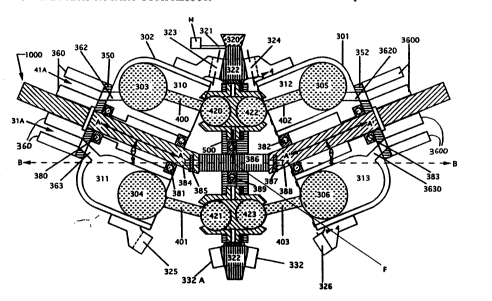
FIG. 3 is a front sectional view of a twelve cylinder axial piston air compressor.
~:IG. 4 is a front plan view of a rotating cylinder housing taken along line 44 of FIG. 3.
FIG. 5 is a longitudinal sectional view of one embodiment of a piston which could be used
in the device shown in FIG. 3.
FIG. 6 is a front plan view of control valve disk 350 of FIG. 3.
~IG. 7 is a central axial view of the air compressor's motion of operation as taken from
FIG. 3 along line B-B. The view is shown as line 7-7 of FIG. 8.
FIG. 8 is a front plan view of the air compressor's mo~ion of operation, the same view as in
FIG. 3.
FIG. 9 is a front sectional view of an alternative embodiment of a twelve cylinder axial
piston air compressor.
Befor~explaining the disclosed embodiment of the present invendon in detail, it is
to be understood that the invention is not limited in its applicadon to the details of the
particular alTangement shown, since the invention is capable of other embodiments. Also~
the terminology used herein is for the purpose of description and not of limitation.
WO 94/10444 : . PCr/US93/09193
2129971
Best Mode for Carrying Out the Invention
Ref~rring first to FIG. l(a), a rota~ing disk 1 rotates in direction ~ I in pl~n~ P 1 A
s~con~ rotating disk 2 rotates in direc~ion R2 in plane P2 synchronously with first rota~ing
disk 1. Planes Pl, P2 must not be parallel.
A piston 6 is mounted to first rotating disk 1 by means of a connecting rod 7. Acylinder 5 is mounted to second rotating disk 2. Cylinder 5 has a one way inlet valve 3 and
a one way exhaust valve 4.
ln FIG. l(a), point B on the first rotating disk 1 is at its nearest distance to poin~ A
on second rotating disk 2. Piston 6 is fully extended into cylinder 5, thereby compressing
maximally volume Vl and forcing compressed air out of exhaust valve 4.
In FIG. 1(b) points B, A are at their midpoint distance. and piston 6 is in a
downstroke, thereby causing a vacuum in volume V2 and subsequently pulling intake air
throu~h inlet valve 3. In FIG. l(c) points B, A are maximally sepasated, piston 6 is about
~o begin a compression stroke, and volume V3 is at maximum capacity vith intake air.
Motor 8 turns drive shaft 81 thereby rotating first rotating disk 1. Linkage L
synchronously rotates second rotating disk 2. Linkage L is generally comprised of a worrn
gear well known in the art.
Planes Pl, P2 can never be parallel. When extended they must form an
intersection. This enabies distances A, B to vary.
Refe~ing next to FIGS. 2 (a)(b)(c), a motor 80 turns drive shaft 801 thus rotating
first rotating disk 10 in direction Rs. Linkage Ll synchronously rotates second rotatin
disk 100 in direction R4 which, by means of linkage L2, synchronously rota~es third
rotating disk 300 in direc~ion R3. Angles C, D are equal and always greater than zero
degrees but never equal to or greater than 90 degrees. Therefore the distance betw~en
points A" - B' and B' - A' varies in unison durin~ the rota~ion of rotatin~ disks 10,100. 30().
Pistons 60,61 mounted on connecting rods 70,71 move inside cylinders 20(), 201
the same as in FIGS. l(a)(b)(c). However, pistons 60, 61 now compensate for each other's
compression forces, thereby creating a low noise, low vibration system. Input valves 3(),
31 and output valves 40,41 cooperate as in ~;IGS. l(a-c) above.
Volume V1O is compressed. Volume V 110 is expanding. thereby creating a
vacuum and causing the intake of air through inlet valve 30. Volume V1OOO is maximal,
and the air insid,e is ready to be compressed.
The ma'xirnally efficient embodiment for the present invention is achieved with a
twin 'six-shooter' design as shown in FIGS. 3,4,9. The central rotating piston disk 5()0 ha~
two pair of six opposing pistons 303, 304,305, 306, etc. Each rotating cylinder housin
301,302, contains six cylinders 310, 311,312, 313, etc.
WO 94/10444 2 1 2 9 9 7 1 PCr/lJSg3/Ogl93
.. I . . ... . .
A drive shaft 321 (powered by a motor M) turns a driving gear 32(). Dnving ~ear
32() in turn drives ~he peripheral gear 322 fastened to the outer rim of the rotating piston
disk 50().
The peripheral 8ear 322 has bevel gear teeth 323, 324, 332. 332A which mesh withteeth 325, 326 and tnereby rotate rotating cylinder housin~s 301, 302. ln the below
description only four of the twelve cylinders are shown, and the tenn "etc." is used to
include identical parts not shown.
Stationary manifolds 360, 3600 communicate to all twelve cylinders 310, 311, 312.
313, etc. by means of twelve revolving cylinder ports 362,363, 3620, 3630. etc. Revolving
cylinder ports 362, 363,3620, 3630, etc. are revolving around the cylinder spindles 388,
384. Two stadonary control valve disks 350 and 352 provide input and output timing as
well as a sliding surface between the stadonary manifolds 360 and 3600 and the rotating
cylinder housings 302,301.
The funcdons of input and output as described as input valves 30,31 and output
valves 40, 41 in l;lG. 2(a) are described below for the device shown in FIG.3.
Referring next to FIGS. 6, 3 the control valve disk 350 is shown mounted in a
stationary fashion between the stadonary manifold 360 and the rotadng cylinder housing
302. In FIG. 3 the piston 304 has moved downward in cylinder 311 dunng the intake cycle. ~ -
The revolving cylinder port 363 has moved from angle 45 deg. to angle 170 deg. while
~communwating whh stadonary valve inlet pon 31A (part of stadonary manifold 360) by
~means of inlet slot 3001.
In a~similar manner the piston 303 in cylinder 310 is in the position of exhausdng
compressed air;in the fimal stages of the exhaust cycle. The compressed exhaust air is
traveling out revolving cylinder port 362, through the stadonary valve exhaust port 41A
(pan of stadonary manifold 360) by means of output slot 3002 as shown in PIG. 6.Pistons 303, 305 are in the exhaust position. Pistons 304, 306 are completing the
intake cycle. '
Rotating cylinder housings 301, 302 and axial piston rotating disk 500 are all
; supponed by and rotate around stationary spindle 1000. Stationary spindle assembly 1000
is funher comprised of axial piston spindle 386, and cylinder spindles 384,388. Each
spindle 386, 384, and 388 has a central axis. The cylinder spindle 388 is opposing cylinder
,spin~dle 384. Bea,rings 380, 381 suppon rotadng cy~nder housing 302. Design choices (not
shown~) would replace stationary spindle 1000 with a driving shaft.
Rotating piston disk 500 and rotating cylinder housings 301 and 302 are preferably
of,the same diameter. thereby easily synchronized by peripheral gears of the same
diameter.
Bolt 385 connects cylinder sphdle 384 to axial piston spindle 386 having bearing389 which rotatably suppons rotating piston disk 500. Bolt 38~ connects axial piston
. .
WO 94/10444 ` PCr/US93/09193
2129~71
spindle 386 to cylinder spindle 388. Bearings 382, 383 rotatably support rotating cylinder
housing 3S)1.
The axial limit A-A of rotating cylinder housing 302 lies entirely ahove the central
axis B-B of axial piston rotating disk 500. The larger the intersecting angle between A-A
and B-B, (the intersecting angle between the central axis of axial piston spindle 3X6 and
the central axis of cylinder spindle 384), the larger the available displacement of all
cylinders. Correspondingly the greater the capability to provide increased volume and
pressure. The preferred embodiment of the present invention uses approximately a 25
degree angle for 13. This design enables all twelve cylinders 310, 311, 312,313 etc. to have
rela~ively large volumes as compared to the known art of hydraulic axial piston
compressors which place A-A in an intersecting alignment with B-B.
The present invention's placement of A-A over B-B also creates a force vector F on
rotating piston disk 500. Porce vector P is absorbed by axial piston spindle 386. Piston
t`orce vectors may also occur due to faulty valving, and such vectors are also absorbed by
cylinder spindles 384,388. This design eliminates the need for a force absorbing case
having a central rotating spindle and a heavy external bearing means, the known hydraulic
axial piston device art.
The pistons 303, 304,305, 306, etc. have connecting rods 400, 401,402, 403, etc.which are mounted in swivel joints 420, 421, 422, 423 etc. PIG. 8 shows how piston
assemblies 911,912 travel in a pattern where the swivel joints (analogous to 420) travel in
circle 500A. The distal ends of the pistons (analogous to 303) travel in ellipse E due to the
angular offset of A-A over B-B as shown in FIG. 3.
Design choices (not shown) for the above invention include a dry lube surlace and a
high coefficient of thermal conductivity for ~he walls of all cylinders, low mass for all
connecting rods and piston heads, and a steel stationary spindle 1000. Cooling fins may be
added to rotating cylinder housings 301,302.
Design choices for valving (not shown) include the replacement of all control valve
disks with output check valves at the cylinder heads. lnput valves at the cylinder sides or
through hollow connecting rods could also be used.
Design choices (not shown) for peripherally driving the rotating components
include applying torque to either outer rotating cylinder housing. The torque is transferred
to the other two rotating components by means of a central synchronizing gear.
Refening next to FIG. 4 rotating cylinder housing 301 is seen to have cylinders
312,313 and four identical cylinders. This assembly is rotatably supported by cylinder
spindle 388 having bearings 382 and 383 ff;IG. 3).
Referring next to FIG. S a generic piston assembly P303 has a polyimide spherical
piston head 2100. an aluminum connecting rod 2101, and a spherical base 2102. Design
choices (not shown) would include cylindrical piston heads with or without piston rings.
WO 94/lO444 2 1 2 q 9 7 1: PCr/US93/09193
Referring next to FIG. 6 a generlc control valve disk 350 has a central mountinghole 3t)()0. The input stroke slot 3()1)1 provides a relatively lon~ duration o~` amhient g~
pressure input, while the output slot 3002 provides a high pressure relativ~ly shor~ duration
output. Design choice for the control valve disk 350 would include a polyimide material.
Referring next to FIGS~ 7, 8 the motions of the piston assemblies 911, 912 are
shown. These motions occur in any device similar in design to FIGS. l(a-c), 2(a-c), 3, 4.
The view in FIG. 7 is taken from line 7-7 in ~;lG. 8.
nG. 7 shows a view taken from the exterior of a rotating cylinder housing and atthe proximal end of the central axis of rotation of the rotating piston disk. This view would
be along line B-B of FIG. 3. The circle 500A in FIGS. 7,8 is equivalent to the rotational
motion of rotating piston disk 500 in FIG. 3. Therefore, the proximal end (the spherical
base 2102 of EiIG.5) of a piston assembly travels in a circular path.
The distal end of piston assemblies 911,912 (the piston head 2100 of FIG. ~) travel
in an ellipse E.
Cylinders (as in 310,311, 312,313 of FIG. 3) are rigidly incorporated within to
their respective rotating cylinder housings 301,302. The cylinders are constrained to take a
circular path revolving about the rotating cylinder housing axis of rotation.
The distal end of piston assemblies 911. 912 of FIGS.7,8 are constrained to takeellipdcal path E. This modon is equivalent to the modon of pistons 303,3W, 305, 306 of
FIG. 3 about central axis B-B. Additionally the motion of pistons 303,304, 305, 3(K take
an ellipdcal path around the central axis A-A of rotadng cylinder housings 301,302.
- It is, therefore. known in the art that the relative modon of the pistons 303,304,
305,306 with respect to their cylinders is a result of relative revolving motions only. This
axial piston art does not use any reciprocating motions at all.
In an alternative embodiment as shown in FIG. 9, the means for torque transfer
amongst all the rotadng components 500, 301,302 consists of a universal joint assembly
725. Universal joint assembly 725 further comprises joint members 726,727 which rotate
with their respective rotating components, thereby absorbing shocks therebetween. Joint
members 726,727 may be of several constructions including elastomeric joints, bevel gears
or interdigitating tines (intermeshing prongs).
Another embodiment (not shown) uses the well known drive means of replacing
stationary spindle 388 with a universal joint drive shaft driving one outboard rotating
cylinder housing. The spinning torque is transferred to the other rotating components in the
manners described above.
Key
13 Angle between the central axis of axial piston spindle
and the axial limit of rotating cylinder housing
W094/lO444 21 29971 PCI/US93/09193
1, 1(), 1()() Rotatin~Disk~s
lO(H) Stahonary Spindle Assembly ~:
2 Rota~ingDisk
200, 201 Cylinders
2100 Piston Head
21()1 Connec~ing Rod -~
2102 Connec~ing Rod Swivel End ~ :
3, 30 Inlet Valves
300 Rotatingl:)isk
3000 Mounting Hole
3001 Inlet Slot
3002 Output Sl~t
301,302 Rotating Cylinder Housings
303,304,305.306 Pistons
31 Inlet Valve
310,311,312.313 Cylinders -
31A Valve Inlet Port -
320 Driving Gear
321 Drive Shaft
322 Peripheral Gear
332,332A,323,
324,325,326 Teeth
350,352 Control Valve Disks
360,3600 Stationary Manifolds
362,363,3620,3630 Cylinder Ports
380,381,389,382,
383 Bearings
385,387 Bolts
388,343 Cylinder Spindles
386 Axial Piston Spindle
4 Output Valve
41A f Valve Exhaust Porl
400,40I,402,403 Connecting Rods
41, 41A Output Valves
420, 421, 422, 423 Swivel Joints ~ :
Cylinder
500 Rotating Piston Disk
500A Circular Path of Motion
9 ,~,
W094/l0444 21-2~971`` PCr/US93/09193
6. 60, 61 Pistons
7, 70, 71 Connecting Rods
7-7 Viewpoint for Fig. 7 (refer to FIG. 8)
72~ Universal Joint Assembly
726,727 JointMembers
8,80 Motors
81, 801 Drive Shafts
911,9l2 PistonAssemblies
A-A, A'-A' Axial I~nits of the Rotating Cylinder Housings
B-B Central Axis of Axial Piston Spindle 386
C Angle
F Vector
D Angle
E Elliptical Path of Motion
L, Lli L2 Linkages
M Motor -'
Pl, P2 Planes of Rotation
- ; P303 PistonAssembly
Rl, R2, R3,R4,R5 Directions of Rotation
VlO,V'llO,V1000,
Vl, V2, V3 Volumes
Although the present invention hæ been described with reference to preferred
emhodiments, numerous modifications and~ variations can be made and still the result will
c o ,me within the scope of the invention. No iimitation with respect to the specific
embodiments disclosed herein is intended or should be infer ed. '
lndustrial~Applkability ~::
The present invention relates to an air compressor having synchronously rotating~ disks at different axes (also called an axial piston design), each disk having a piston or a `~
cylinder. Thus, a piston oscillates in a cylinder by means of rotadons rather than traditional
reciprocadon. ;~
~~, ;:
'`~
.
,