Note: Descriptions are shown in the official language in which they were submitted.
2~ ~2~
'``
1554 (203-1237)
FOUR SLIDER APPARATUS F0R F0RMING
CURVED RECTANGULAR BODIED NEEDLES
BACKGROUND OF THE INVENTION
1. Field of the Invention
The present invention relates to ne~dle forming
devices. More particularly, the invention relates to a
multistation needle forming apparatus for simultaneously
flat pressing, and curving and then side pressing a needle
blank to form curved, rectangular bodied needles. The
apparatus is capable of forming the needle blank about a
single forming member.
2. Descri~tion of the Related Art
The production of needles involves many processes
and different types of machinery in order to prepare quality
needles from raw stock. These varying processes and
machinery become more critical in the preparation of
surgical needles where the environment of intended use is in
humans or animals. Some of the processes involved in the
production of surgical grade needles include, inter alia:
straightening spooled wire stock, cutting needle blanks from
raw stock, tapering or grinding points on one end of the
blank, providing a bore for receiving suture thread at the
other end of the blank, imparting flat surfaces on opposite
sides of the blank by flat pressing a portion of the needle
blank to facilitate grasping by surgical instrumentation and
curving the needle where curved needles are desired.
-- -2~13~2~3
Additional processing may be done to impart flat surfaces
su~stantially perpendicular to the flat pressed portions of
the needle blank by side pressing a portion of the needle
blank to furthPr facilitate grasping by surgical
instrumentation and insertion into humans or animals.
Conventional needle processing is, in large part, a labor
intensive operation requiring highly skilled labor.
Generally, extreme care must be taken to ensure that only
the intended working of the needle is performed and the
lo other parts of the needle remain undisturbed.
Curved rectangular bodied needles have advantages
over other needle configurations in many surgical procedures
for a variety of reasons including, uniformity of entry
depth for multiple sutures and proper "bite" of tissue
surrounding the incision or wound. When providing curved
rectangular bodied needles for surgical procedures it is
desirable for the needles to have a specified rectangular
cross-section and a specified curvature, i.e., a
predetermined radius of curvature. The desired cross-section
and radius of curvature for the finished needle varies with
specific applications.
Known methods of forming curved rectangular bodied
needles require several separate and distinct operations on
various machinery. The needle blank must first be flat
pressed to impart initial flat surfaces along body portions
of the needle blanks located between a tapered point end of
the blank and a drilled end. After flat pressing, the
needle blank can then be taken from the flat press dies to a
curving machine to impart the proper curvature to the needle
blank. Care must be taken when removing the blanks from the
,~
~ 'h
,' -3- ~3~2~
flat press dies and positioning the needle blank in the
curving machinery to avoid disturbing the flat surfaces
imparted by the flat pressing operation. After curving, the
flat pressed and curved needle blanks can then be taken from
the curving anvil to a side press station to impart flat
surfaces substantially perpendicular to the flat pressed
sides to give the final rectangular cross sectisnal profile
to the needle body. Again care must be taken during removal
of the needle blanks from the curving anvil and during side
pressing so as to avoid disturbing the previously imparted
flat pressed and curved portions of the needle blank.
When needles are made of steel or similar
resilient materials, the anvil or mandrel used should have a
smaller radius than the radius desired in the final needle.
This configuration allows for some springback after the
bending operation and ensures that the desired radius of
curvature is attained. A disclosure of such features may be
found in, for example, U.S. Patent No. 4,534,771 to McGregor
et al. Needles improperly positioned on the anvil may result
in a deformation of the previously imparted flat press sides
and may have to be reprocessed or discarded.
One disadvantage to conventional needle forming
techniques is that typically only one needle processing
operation at a time, such as, for example, flat pressing
between a pair of dies, curving around an anvil structure or
side pressing between another set of dies, can be performed
on a single piece of machinery. A further disadvantage is
the long processing time and high costs required in forming
and transporting the needles between the various machinery.
Lastly, a still further disadvantage is the need to readjust
.
,.: .- : ,. , .. , : , . - .. ~ : . . ... . . . .
_4- 213~
several pieces of machinery to process needles of varying
lengths and diameters thereby further increasing production
time and costs.
Therefore, a need exists for a single needle
forming apparatus that is capable of simultaneously flat
pressing, and curving, and side pressing a simultaneously
needle blank by forming the needle blanks about a single
forming member of the same apparatus. It is also desirable
to provide a needle forming device which cooperates with a
needle feeding fixture for sequentially loading and
positioning one or more needles against the forming surface
so as to increase the production rate of the needle
manufacturing process by maintaining a continuous flow of
needle blanks through the device.
SUMMARY OF THE INVENTION
There is disclosed an apparatus which includes a
frame portion and means associated with the frame portion
for substantially simultaneously imparting an arcuate
profile and a first pair of opposing flat surfaces to a body
portion of a needle blank. The apparatus further includes
means associated with the frame portion for imparting a
second pair of opposing flat surfaces to the body portion of
the needle blank such that the second pair of opposing flat
surfaces are substantially parallel to the first pair of
opposing flat surfaces. In particular, there is discloses
an apparatus for forming a curved, flat sided surgical
needle, which includes a frame member including an anvil
member having an arcuate surface profile; a movable first
die member for imparting an arcuate profile to a first pair
:
-5- 2~ 3~2~
of opposing sides of a body portion of a needle blank and
adapted to receive a needle blank, the first di~ member
having an arcuate needle forming surface which is
substantially parallel to the arcuate surface of the anvil
member; and a first side tool for curving a tapered end
portion of the needle blank about the anvil; there is also
provided a transfer tool adapted to slide the needle blank
along the anvil; a side press adapted to import second flat
surfaces to second opposing sides of the body portion of the
needle blank; a second side tool member for curving a
drilled end portion of the needle blank about the anvil; and
an ejection tool for moving the needle blank away from the
anvil.
BRIEF DESCRIPTION OF THE DRAWINGS
Preferred embodiments of the invention are
described hereinbelow with reference to the drawings
wherein;
Fig. 1 is a perspective view of the needle forming
apparatus of the present invention;
Fig. 2 is a top plan view of the needle forming
apparatus of Fig. 1;
Fig. 3 is a side elevational view of the needle
feeding mechanism of the apparatus of Fig. l;
Fig. 4 is a perspective view of the top slide
plate and the auxiliary slide plate thereof;
Fig. 5 is a partial top plan view of the top slide
plate and forming mandrel prior to forming a needle blank
thereof;
,:~ " :, :,- : ' "~ ''
_ -6- 2~3~
Fig. 6 is a partial top plan view of the top slide
plate forming a needle blank about the mandrel thereof;
Fig. 7 is a partial perspective view of the right
side bending tool die;
Fig. 8 is a partial top plan view of the right
side bending tool die forming the tapered point end of the
needle about the mandrel;
Fig. 9 is a partial perspective view showing the
transfer tool engaging a partially formed needle blank;
Fig. 10 is an enlarged partial side view
illustrating the side press;
Fig. 11 is a partial top plan view showing the
left side forming tool engaging the needle blank;
Fig. 12 is a partial perspective view showing the
ejection tool;
Fig. 13 is a perspective view illustrating a
surgical needle formed according to the apparatus of Fig. l;
Fig. 14 is a partial perspective view illustrating
the relationship of the top slide tool, the auxiliary slide
tool, the right slide tool and the transfer tool relative to
the mandrel member; and
Fig. 15 is a perspective view similar to Fig. 14
illustrating the operation of the side press die.
DETAILED DESCRIPTION OF THE PREFERRED EMBODIMENT
Generally, the needle forming apparatus of the
present invention is utilized to simultaneously curve and
flat press a needle blank and then side press a body portion
of the blank in order to form a curved, rectangular bodied
needle. Means are provided for protecting tapered and
drilled end portions of the needle blanks during the forming
:, .~ ., - : ; - . , , ~ ~ , ~ , .
:., ' ' ' ' '- ,.~ " ' ': , , .
f' '~
.. . . . . . . . . . .
~ -7- 2~3~
operations. As used herein, the term needle blank refers to
a surgical needle in various stages of fabrication.
Referring to Figs. 1 and 2, needle forming
apparatus 10 generally includes a support stand or frame 12,
a feeding hopper 14, a needle forming station 16 and an
offload conveyor belt 18. As used herein, the term "frame
12" refers at various times to all or part of the supports
or frame members of apparatus 10 used to support the
operative machinery as the situation may necessitate.
Apparatus 10 also includes a front camshaft 20, a
right side camshaft 22, a left side camshaft 24 and a rear
camshaft 26. Camshafts 20, 22, 24 and 26 are driven by
motors 28, 30, 32 and 34, respectively, and are provided to
drive and sequence the movements of the various die plates
and tools of apparatus 10 by known methods. A toggle tower
36 houses a toggle link 38 used to operate the side press ~ -
die. Control stations 40 and 42 are provided to control the
various motors and thus the operation of apparatus 10.
Referring still to Fig. 1, a flywheel 44 may be
provided on one of the shafts to stabilize the motions of
the various cam shafts. A safety mechanism, in the form of
25 a guard rail 46, is provided to protect the user. A sensor `
(not shown) may be incorporated into guard rail 46 and used
to shut off apparatus 10 when an operator or bystander
crosses over guard rail 46. Further, a light 48 may be
provided to illuminate needle forming station 16 to aid in
viewing the needle forming operations.
~, . . ' :: ; :
r~r , ~ ., ~ ., ,.. , : ~ ~ ., ~ ~ ,
k ` - ~ ~
~, . ,, ~ " . . .
~ 8- 213~2~ ~
Referring now to Fig. 2, front camshaft 20
includes four cams 50, 52, 54 and 56 which control the
motions of a front tool 58, an auxiliary plate 60 and a
transfer tool 62, respectively. Cams 54 and 56 control the
horizontal and vertical motions, respectively, of transfer
tool 62. Right side camshaft 22 includes a cam 64 which
controls the motions of a right side tool 66. Left side
camshaft 24 has a cam 68 which controls the motions of a
left side tool 70. The last camshaft, rear camshaft 26, has
a pair of cams 72 and 74 which control the motions of toggle
link 38 and an ejection tool 76, respectively. As noted
above, the various cams on the cam shafts sequence and
control the travel and dwell of the various die and tool
members using known methods.
As shown in Fig. 3, feeding hopper 14 is adapted
to hold a plurality of drilled and tapered needle blanks and
transfer the blanks one at a time to front tool 58. Feeding
hopper 14 includes a back plate 78, a pair of side plates 80
and a front plate 82 which is angled with respect to back
plate 78 to form a V-shaped needle holding hopper
therebetween. Preferably, side plates 80 are formed of a
transparent material such as, for example, a plastic
material, to facilitate observation of the amount of needle
blanks remaining in hopper 14. Back plate 78 may include a
mounting block 84 for detachably mounting hopper 14 on frame
12. Hopper 14 further includes a feeding mechanism 86 for
transferring one needle blank at a time from hopper 14 to
front tool 58. Feeding mechanism 86 includes a box 88
containing upper and lower feed rods 90 and 92,
respectively. Upper feed rod 90 drops one needle at a time
into a staging area 94 and lower feed rod 92 moves against a
- -9- 2 1 3 ~
spring 96 to deposit one needle at a time into front tool
58. Feed rods 9o and 92 are controlled by solenoid
controled pneumatic cylinder.
Referring now to Figs. 3 and 4, front tool 58 is
provided to receive a needle blank from feed mechanism 86
and simultaneously curve and flat press a body portion of
the needle blank against an elongated, curved forming
surface or mandrel 98 as shown in Figs. 5 and 6. Front tool -
58 includes a main body portion 100 having a pair of
projecting portions 102 each of which are provided with a
needle supporting surface 104. Body portion 100 further
includes an arcuate die face 106, positioned between
projecting portions 102, which is dimensioned and configured
to simultaneously impart an arcuate profile and a pair of
opposing flat surfaces to a body portion of the needle blank
when pressed against mandrel 98. Surface 106 may have a
radius of about 0.05 to 3.00 and preferably of about 3.00. ~ ;
Surface 106 is parallel to mandrel 98 to impact opposing
flat surfaces to a needle blank pressed therebetween. Front
tool 58 may further be provided with a pair of pivoting
retention arms 108 mounted on body portion 100. Retention
arms 108 help define a recess for receipt of a needle blank
and help hold the needle blank in place on surfaces 104 when
front tool 58 is moved from a position adjacent feeding
station 16 to a position near mandrel 98.
As shown in Figs. 5 and 6, front tool 58 is
moveable from a first position remote from mandrel 98 where
front tool 58 receives and retains a needle blank to a
second position where retention arms 108 pivot upwards to
allow die face 106 to partially form the needle blank about
-lo- ~3~2;3~
-
mandrel 98. Die face 106 partially forms the needle blank
by simultaneously curving the body portion of the blank
around mandrel 98 and flat pressing the portion of the
needle blank body between die face 106 and mandrel 98.
Mandrel 98 is preferably provided with a radius of about
0.05 to about 3.00 and preferably about 3.00. As further
shown in Fig. 6, only the body portion of the needle blank
extending from points x to y is curved against mandrel 98
through an arc B of about 135 degrees. This prevents
tapered and drilled end portions of the needle blank from
being flat pressed between mandrel 98 and front tool 58.
Referring again to Fig. 4, auxiliary plate 60 is
located beneath front tool 58 and has an arcuate surface 110
at one end thereof which corresponds to the arcuate surface
front tool 58. Arcuate surface 110 of auxiliary plate 60
helps define a space between auxiliary plate 60 and mandrel
98 for receipt of the needle blank, as shown in Fig. 9, and
to maintain the blank against the mandrel during curving of
the drilled end portion of the blank and side pressing of
the body portion of the blank. A side block 112, affixed to
auxiliary plate 60 and offset from front tool 58, is
provided to receive the motions of cam 52 move auxiliary
plate 60 independently of front tool 58.
As noted above, front tool 58 is adapted to curve
the body portion of the needle blank between die face 106
and mandrel 98. In order to provide a true continuously
curved needle blank it is also desirable to curve the
tapered end portion and drilled end portion of the needle
blank. However, this must be done in a manner which ensures
.. . .. .
3 ~ ~ 5 ~,
that the tapered and drilled end portions are not damaged or
distorted.
As shown in Figs. 7 and 8, right side tool 66 is -
provided to curve the tapered end portion of the needle
blank while the needle blank is held against mandrel 98 by
front tool 58. Right side tool 66 includes a body member
114 and a pair of curving arms 116 and 118 terminating in
curving faces 120 and 122, respectively. Curving faces 120
and 122 are dimensioned and configured to bend the tapered
end portion of a needle blank about mandrel 98 without
damaging the tapered end portion in any manner. Further,
curving arms 116 and 118 are biased out from body member 114
by springs 124 and 126, respectively, to further cushion the -~
pressure of faces 120 and 122 against the taped end portion.
Still referring to Figs. 7 and 8, right side tool 66 is
movable from a position remote from the needle blank held
between front tool 58 and mandrel 98 to a position abutting
the tapered end portion of the needle blank to gently curve
the tapered end portion about mandrel 98~ As noted above,
the motions of right side tool 66 are controlled and
sequenced by camshaft 22 and, in particular, cam 64.
In order to ensure rapid, consistent and reliable
formation of a needle blank, it is desirable to feed the
needle blanks into forming stations 16 from hopper 14 above
front tool 58 and eject the fully formed needle blank out
beneath front tool 58 and onto offload conveyor belt 18.
Thus, once the tapered end portion of the needle has been
curved it is preferable to slide the needle blank down
between mandrel 98 and front tool 58 to a position between
-12- 2~3i~2~
auxiliary plate 60 and mandrel 98 and adjacent a lower side
die face 128.
As shown in Figs. 9, 14 and 15, transfer tool 62
is provided in order to rapidly and consistently move the
needle blank down along mandrel 98. Transfer tool 62
includes a stem portion 130 ending in an arcuate transfer
arm 132. Transfer arm 132 is of approximately the same
radius of curvature as mandrel 98 and has a thickness of
less than or equal to the thickness of the flat pressed
needle blank. Stem 130 is held by a block 134 which is
biased upwards by springs 136. Transfer tool 62 is movable
horizontally toward and away from mandrel 98 by means of cam
54 and is slidable vertically along mandrel by means of cam
56. In this way transfer tool 62 is movable along a
generally rectangular path to drive the needle blank down
along mandrel 98, move back with front tool 58, rise and
move forward to an initial position above front tool 58.
As noted above, in order to form a curved,
rectangular bodied needle, it is necessary to side press the :
body portion of the needle blank without damaging the
tapered or drilled end portions of the needle blank. As
shown in Fig. 10, an upper side press die 138 is provided to
impart flat surfaces on sides of the needle blank
substantially perpendicular to the flat pressed sides by
pressing the body portion of the blank between an upper die
138 and lower die face 128 to impart the final rectangular,
and preferably square, cross-section to the body portion of
the needle blank. In order to ensure that only the body
portion of the needle blank is side pressed, upper die 138
and lower die face 128 trail off or angle back from a
-13- ~3i32J ~
transition point A in order to provided a margin of
clearance for the tapered and drilled end portions of the
needle blank. The degree of these angled back portions or
tapers are on the order of about 1 to about 10 and
preferably about 2 to about 4. As also shown in Fig. 10,
a forward surface 140 of lower die face 128 angles downward
to help direct a finished needle blank onto offload conveyor
belt 18 during ejection of the blank from needle forming
station 16. -
The last step in forming the curved, rectangular
bodied needle is to curve the drilled end portion of the
needle blank, again, without damaging the drilled end
portion. As shown in Figs. 11 and 15, left side tool 70 is
provided to curve the drilled end portion of the needle
blank, while it is held in place on mandrel 98 by auxiliary
plate 60, and includes an arcuate forming surface 142.
Surface 142 is adapted to bend the drilled end portion of
the needle about mandrel 98 without damaging it. Left side
tool 70 is driven by cam 68 on cam shaft 24.
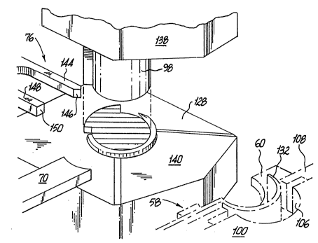
Referring now to Figs. 12 and 15, ejector tool 76
is provided to push the fully formed needle blank away from
mandrel 98 and onto offload conveyor belt 18. Ejector tool
76 has an angled first pushing arm 144 having an angled tip
146 and a flat second pushing arm 148 having a blunt or flat
tip 150 for engaging the tapered and drilled end portions of
the needle blank, respectively. Cam 74 and rear cam shaft
26 drives ejector tool 76 to push a needle blank free from
mandrel 98 in needle forming station 16.
~ -14- 2~33~
Preferably, the tool and die members of apparatus
lO are formed of a steel having a hardness substantially
greater than or equal to that of the needle blank. The tools
and dies have a Rockwell hardness of about (55C) to (70C)
5 and preferably about (62C). -~
In operation, a plurality of tapered and drilled
needle blanks are initially loaded into hopper 14. The
speed of apparatus lO and the motions of the various members
are programmed into the machine by means of control panels
40. Depending upon the sizes of the needle blanks process,
various parameters such as die pressure, motor speed and
die-strokes would be set on control stations 40. As noted
above, a safety mechanism in the form of a sensor may be
built into guard rail 46 to prevent operation of apparatus
lO until all users and bystanders are cleared away from the
machinery. These safety features prevent hands or fingers
from becoming caught in the various cam and die members
during operation.
Referring now to Fig. 3, needle blanks initially
loaded into hopper 14 move down between back plate 78, front
plate 82 and side plates 80 toward staging area 94. Upper
feed rod 90 is retracted a sufficient amount to allow a
single needle blank to fall into staging area 94. It will
be noted that at an initial start position of each full
needle forming sequence front die plate 58 is positioned
with needle supporting surfaces 104 located directly below
staging area 94. At this point, lower feed rod 92 is
retracted against the bias of spring 96 to allow a single
needle blank to fall into the space defined by block 100,
needle supporting surface 104 and retention arms 108. As
-15- ~ 3 ~-Js~
~ .
noted above, retention arms 108 aid in maintaining the
needle blank against surfaces 104 while the front die plate
is advanced toward the mandrel member 98.
:
S Referring now to Figs. 5 and 6, as front tool 58
is advanced toward mandrel 98 side retention arms 108 pivot
upwardly to allow the drilled end portion and tapered needle
portion to move forward as tool 58 simultaneously bends and
flat presses the body portion of the needle blank against
mandrel 98. As noted above, curving surface 106 has an
arcuate profile substantially similar to that of mandrel 98.
The surface of mandrel 98 and surface 106 are parallel such
that when pressing a needle blank therebetween, flat
surfaces are imparted to opposing sides of the needle blank.
Thus, simultaneous curving and flat pressing of the body
portion of the needle blank is obtained by pressing the
blank between mandrel 98 and front tool 58. As further noted -
above, once the needle blank has been curved and flat
pressed, it is desirable at this stage to continue the
arcuate profile around to the tapered end portion of the
needle blank.
As shown in Figs. 7 and 8, the right side tool 66
comes in causing arms 116 and 118 to gently impinge upon the
tapered end portion of the needle blank thereby curving the
tapered portion about the mandrel. Springs 124, 126 aid in
softening the impact of the arms 116 and 118 respectively
against the drilled needle blank. Curved faces 120 and 122
are sufficiently recessed so as to prevent any damage to the
tapered end portion of the needle blank during this curving
step. It will be noted during the curving of the tapered
end portion of the needle blank, the needle blank is held
-16- 213~7~3
against mandrel 98 in a position slightly above lower die
face 128 by means of curving face 106 of front tool 58.
After curving of the tapered end portion of the needle
blank, right side tool 66 retracts to its initial position
away from mandrel 98 as shown in Figs. 7 and 15.
As can be seen in Fig. 14, transfer tool 62 is
initially disposed above the curved and flat pressed needle
blank along mandrel 98. It is desirable at this stage to
move the needle blank down along mandrel 98 to position
adjacent lower die face 128 for side pressing of the needle
blank, curving of the drilled end portion of the needle
blank and final ejection of the needle blank down surface
140 onto off-load conveyor belt 18.
Referring now to Fig. 9, it can be noted at this
point front tool 58 retracts slightly to allow transfer tool
62 to slide down between inner surface 106 of front tool 58
and mandrel 98 thereby pushing down the needle blank into
the gap formed between auxiliary plate 60 and mandrel 98.
Transfer tool 62 is driven downward toward the bias of
springs 136 by means of cam 56 on the front cam shaft 20 and
rocking lever 57. Specifically, cam 56 pivots rocking lever
57 which abruptly moves transfer tool 62 against the needle
blank to drive it downward between the gap formed by
auxiliary plate 90, auxiliary plate 60, mandrel 98 and lower
die surface 128. As noted above, and as seen in Fig. 10,
auxiliary plate 60 has a thickness which is approximately
slightly less than or equal to the thickness of the final
cross-sectional area of the side pressed needle blank. Once
the needle blank has been moved down mandrel 98 by transfer
tool 62, front tool 58 and transfer tool 62 retract to
-17- 2 ~ 3 ~
provide clearance for upper die 138 and return to their
original start positions.
Referring now to Fig. 10, at this point cam 72 on
rear cam shaft 26 operates toggle linX 38 in toggle tower 36
to drive the upper die 138 down against the needle blank,
thereby side pressing the needle blank between upper die 138
and lower die surface 128 to impart a final rectangular
cross-sectional shape to the body portion of the needle
blank. As noted above, tapers a in upper die 138 and low
die surface 128 provide clearance areas for the tapered end
portion and drilled end portion of the needle blanks such
that material in those areas are not side pressed. In a
preferred embodiment, these tapered portions or these angled
portions or tapers are on the order of about 1 to about 10
and more preferably on the order of about 2 to about 4.
Referring now to Figs. 11-13 and 15, once the
needle has been side pressed by upper die 138, final
processing of the blank can be performed by left side tool
70 which is driven by cam 68 on left cam shaft 24 to impart
the final curve to the drilled end portion of the needle
blank. Tool 70 presses the drilled end portion of the
needle blank between surface 142 of left tool 70 and the
mandrel member 98 as shown in Fig. 11. It will be noted
that during both the side pressing operation with dies 129
and 138 and the curving operation with left side tool member
70, the needle blank is held against mandrel member 98 by
means of auxiliary plate 60. After final curving of the
drilled end portion of the needle blank, auxiliary plate 60
along with front tool 58 and transfer tool 62 retract back ~;
away from mandrel member 98 as shown in Fig 14. Upper die
` -18- 2~3~3~
member 138 and left side tool 70 similarly retract away from
the now fully formed needle blank as shown in Fig. 15.
Referring now to Figs. 12 and 15, after the needle
5 blank has been fully formed, ejector tool 76 is driven
forward by an ejector cam 74 on rear cam shaft 34 to drive
the needle blank off of mandrel 98 and down angled surface
140 onto offload conveyor belt 18. Angled surface 146 at
the end of arm 144 of ejector tool 76 wedges between the
10 tapered point of the needle blank and mandrel 98 to slide
that portion of the needle blank away from mandrel 98.
Similarly, the flat or blunt edge 150 of the arm 148 of
ejector member 176 abuts the drilled end portion of the
needle blank to in conjunction with angled surface 146 drive
15 the needle blank off of mandrel 98 and onto offload conveyor
belt 18.
Apparatus 10 is adapted to handle needles having
lengths ranging from about 0.300 to 2.5 in. A complete
20 forming cycle can take from approximately .3 sec. to 2 sec.
and preferably 1. Thus, apparatus 10 is capable of forming
approximately 60 needles per minute. A curved rectangular
body needle 152 formed on apparatus of the present invention
is illustrated in Fig. 13.
It will be understood that various modifications
can be made to the embodiments of the present invention
herein disclosed without departing from the spirit and scope
thereof. For example, various sizes of the dies are
30 contemplated, as well as various types of construction
materials. Also, various modifications may be made in the
configuration of the parts. Therefore, the above
.... .. , .. , .. . ~ ... . ... . ... . . . .
-19- 2~3~2~3
description should not be construed as limiting the
invention but merely as exemplifications of preferred
embodiments thereof. Those skilled in the art will envision
other modifications within the scope and spirit of the
present invention as defined by the claims appended hereto.
, .
i~.' ~ . ? ' , ~ .