Note: Descriptions are shown in the official language in which they were submitted.
- 1 - 2 1 3 0 S ~
ARC DL.~ ON ~SING ~ VARIATION
BACKGROUND AND SUMMARY
The invention relates to protection te~hn i ques
for electric circuits, and more particularly to the
5 detection of arcs which are tco small to trip a circuit ~-
~reaker or the like.
The invention arose during development efforts
in electric circuit protection te~hn; ques, including
residential, c~ -rcial and industrial applications
having overcurrent protection and/or ground fault inter-
rupter (GFI) systems for preventing property damage
and/or personal injury. OveL~u-Lent protection system
typically include a load center or panPlhoi~rd receiving ;~
electrical power from the utility company transformer,
and routing the electrical power through a main circuit
breaker or fuse and then through branch circuit breakers
or fuses to designated branch circuits, each supplying '
~LLe--L to one or more electrical loads. The circuit
breakers or fuses are ~DCi gned to interrupt the electri-
20 cal current if it is D~Dssive or outside the design ~
limits of the con~llctors and loads or demonstrates a ~;
~uLsel~ imhal~ncD, to reduce the risk of injury and dam- ~'
age, incll~in~ ~ires. Circuit breakers are more commonly
preferred hDci~llc~ they are rel~cAhle simply by resetting
same.
A c~rcuit breaker has a thermal/magnetic trip
characteristic. The thermal characteristic is operative
in ~r~o~-ce to overload ~uLlenL of exten~e~ duration
which heats a bimetal m~mher, causing movement of the
latter, which in turn r~lei~cec a latch to trip open a set
of contacts. For example, the thermal characteristic
would res~.. d to 30 amps being drawn in a 15 amp circuit. ~-
The magnetic characteristic is operative in response to a -
s~ Dn high magnitude ~ULL~I- overload condition, and
uses t'.e magnetic field generated in a magneti~ core to
attract an aL ~~uLe, which movement releases the latch to - '
open the contacts. As an example, the magnetic type
- 2 - 2130S34
- actuation occurs in response to a short circuit wherein
the hot line con~l~ctor h~_ ?-~ directly co~nPcted with
yLO~Id or neutral, byp~-csing the load. ~ ~
A further type of circuit protection is provid- -
ed by a y~ fault interrupter, which trips the breaker
to an open circuit condition in response to an imh~l~n~e
of currents between the line and neutral conductors of a
given circuit~ This is particularly desirable in the
event that a person is in the path to ground.
The present invention addresses a further type
of electric circuit protection and monitoring, namely the
detection o~ arcing in the electric circuit. The arcs to
be monitored include not only a discharge of electricity
through a gas or across an insulating medium, but also
high imped~nce faults or other inten~e~ or unintP~e~
circuit paths which do not have sufficient energy or
current flow to trip a breaker, ~ut nevertheless can
generate damaging heat or other undesirable effects. An
arc may occur in series or parallel with the load, and
may have numerous causes, for example loose connections,
worn or aged wiring or insulation, prior eQh~n;cal or
electr;cAl stressing such as caused by crimping or twist-
ing, overuse, prior lightning strikes, etc. The ~uL-.~.,L
in such arcs may be below the thermal and magnetic trip
settings o~ the breaker or a ~use, and/or may not present
an imh~l~nce o~ ~u~Lcl~Ls baL~en the lins and neutral
_ c~n~ tors, and hence such arcs can go undetected. A
partic~ r hazard due to arcing is hot spots along elec-
trical wiring in a res;~nce or the like, which is a fire
risk. This wiring can include wall co~ ctors, junction
boxes, receptacles, switches, plugs, cords such as exten-
sion cords, and the load devices themselves.
The present invention provides effective arc
detection. The invention is particularly well suited to
~iscriminating between potentially damaging arcs and
either non-arcing events or momentary short duration
swit~hing events, which is desirable in order to ~.evel.L
;, . , ., ~ -- . - - . . , . , ., ".. ; , ...
~ :
- - 2 1 3 0 '~) 3 4 ~ ::
-- 3
n~ nc~ tripping. The invention does not trip in re-
sponse to all arcs, nor all se- ;n~ly arc-like events,- ~
but rather relies upon statistical probabilities to ~ - -
provide an arc indicative signal in response to an event
which has a strong l;kel ihooA of being an arc. To at-
tempt to r~spon~ to all arcs would involve an unaccept~
ably high oc~u lence of n~ nce tripping, which is
undesirabl~ ~ecause it may shut down ma~-h;nPry or safety -
equipment which should remain running, except for those
events actually having a high statistical pr~bability of
being an arc.
BRIEF DESCRIPTION OF THE DRAWINGS
Fig. 1 is a schematic illustration of an elec- ; :~
trical current distribution circuit, and is taken from
Fig. 1 of U.S. Patent 5,185,685, incorporated herein by -~
reference.
Fig. 2 is a schl -tic illustration of a portion
of the circuit of Fig. 1, and is s; il~ to Fig. 2 of the
noted illcuL~uLated ~685 patent.
Fig. 3 is a functional block diagram of an arc
detector in accordance with the invention. ;
_ Fig. 4 i8 a waveform diagram showing AC line
~uL-~.. L ~or one partic~ r example. ~;
Flg. 5 i~ a waveform diagram illustrating
2g operation o~ a portion o~ the circuit o~ F~g. ~.
Flg. 6 i8 a waveform diagram illustrating
_ u~LaLion o~ a portion of the circuit of Fig. 3.
Figs. 7-11 are waveform diagrams illustrating -~
cumulative operation of a portion of the circuit of Fig.
3.
Fig. 12 is a functional circuit block diagram
of the arc detector of Fig. 3.
Figs. 13 and 14 show a reference sine wave with -~
points related in phase l ~h~l l e~
DETAILED DESCRIPTI~N
Fig. 1 shows an electrical current distri-
bution circuit 20 including a load center 22 having a
". :, ;,,~
_ 4 _ 2130S3~ ~
line side 24 for receiving electrical power from a volt-
age source 26 of predet~ ;ne~ excitation frequency, and
a load side 28 distributing the electrical power to loads
such as 30 and/or 81. The voltage source can be a power
utility c~ ,-ny transformer supplying electrical power on
first and secnn~ line conAn~-tors at 240 volts, and a
neuLLdl conductor at 120 volts relative to the first and
~con~ line con~tlrtors~ all at, e.g., 60 Hz. The inven-
tion is not limited to such example, and can be applied
to any AC system operating at any voltage and frequency,
including 480 and 660 volts, and 50, 60 and 400 Hz. The
load center has a main electro-responsive circuit breaker
32 receiving the electrical power fro~ transformer 26 and
distributing the electrical power to branch circuit
breakers 34, 36, etc. The branch circuit breakers in
turn supply the electrical power on branch circuits such
as 38 to electrical outlets 40, 42, etc. into which load
30 is plugged at plug 44, or branch circuit 38 which is
wired directly to load 31. Branch circuit 38 includes a
line con~nctor 46, Fig. 2, and a neutral cond-lctor 48
supplying the electrical power to load 30. Branch cir-
cuit 38 may also include a yLuund con~notor 50. circuit
breaker 34 includes an overload trip me~h~n;sm 52 having
a thermallmagnetic characteristic tripping breaker con-
tact6 54 to an open c~rcuit condition in responsQ to a
g~ven circu~t overload condition, to ~ 8~0n~9ct load 30
- ~rom ths voltage source 26, a~ is known in the prior art.
It is also known in the prior art to provide circuit
breaker 34 with ~,v~.~ fault inte u~Ler circuitry 56
L~.o~ ng to a line or neutral to y ~ulld fault to gate
SCR 58 into con~llction to in turn energize coil 60 which
opens breaker contacts 54. An example of a GFI circuit
is shown in U.S. Patent Re30,678.
3S The present invention provides an arc detector
64 and arc detection method for the electric circuit
supplying AC line ~u.l~llL to load 30 from AC source 26 of
~ 2130~3~
- 5 -
given frequency providing repetitive cycles, e.g. 60 Hz
providing repetitive cycles each having a period of 16.67
milliseconds. Arc detector 64 senses cycle to cycle
changes in AC line current and generates difference
sign~l~ representing such changes, to be descri~ed, and
responds to given conditions of the difference s;gn~l~ to
generate an arc indicative trip signal on line 67 provid- ~ -
ing a gating signal supplied to the gate of SCR 58 to
gate the SCR into conduction and energize coil 60 to open
10 breaker contacts 54. The ouL~uLs of circuits 56 and 64
are connected at a common node 65 to the gate of SCR 58.
I~ the circuit breaker does not have GFI circuit 56, the
SCR 58 and coil 60 are added.
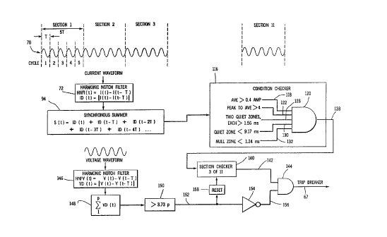
Fig. 3 shows arc detector 64. AC line current
is shown as current waveform 70, Figs. 3 and 4, which is
the AC current supplied on line 46, Fig. 2, from AC
source 26 to-load 30. The current is preferably sensed
with a current transformer, for example as shown at 68 in
the inco~uLated '685 patent, though the ~uLr~L may be
St~nce~l with other ~u~-LenL sensors. The sensed AC line
current is sampled with a harmon~c notch filter 72 at a
plurality of sampling points or phases n during a plural-
ity of cycles m, with the relative phase of the respec-
tive sampling point being the same cycle to cycle.
For example, re~erring to Fig. 4, the AC line
cUrrent is sampled at a pha8e e" 1 during a ~irst cycle
- o~ the AC source to provide a first sampled current I
The first s~hscript is the phase or sampling point and;~
the second s~hscript is the cycle; hence, I1 1 is the
~uu,e~.L at the first phase or sampling point in the first
cycle. The AC line ~uu~ is sampled at a first phase ~ ~-
or sampling point el 2 during a second cycle of the AC
source to provide a sampled current Il 2~ which is the
~uL,~..L at the first phase or sampling point in the
~eco~ cycle. The AC line ~urrent is sampled at the same
relative phase during each of the first and second cy-
cles, i.e. e1 1 equals e1 2 Stated another way, e1,1 and
'b... . . . ... - .. - .. -... . . .... .... , . ~ .
- 6 - 2130S3~
el 2 are spaced or separated by one cycle, or 360~, of
the AC source, or an integral multiple thereof. In the
case of a 60 Hz AC source, e1 1 and el 2 are spaced by
1/60 of a second, i.e. 16.67 i ~ con~ or an integral
multiple thereof. The noted difference signals are
provided by subtracting I1,1 from Il,2.
The AC line current is sampled with the harmon-
ic notch filter at a plurality of phases e1,1 through en
during a first cycle of the AC source to provide a plu-
rality of sampled currents I1 1 through In,l for the firstcycle. The AC line current is sampled with the harmonic
notch filter at a plurality o~ phases 31,2 through ~ 2
during a secon~ cycle o~ the AC source to provide a
plurality of sampled currents I1 2 through In,2 for the
secon~ cycle. e1 1 through en 1 equals e1,2 through en 2~
respectively, i.e. the first sampling point in the first
cycle oc~u,s at the same relative phase as the first
sampling point in the cecQn~ cycle, the second sampling
point in the first cycle O~UL S at the same relative
phase as the second sampling point in the second cycle,
and so on. The sampled currents I1,1 through In,1 are
subtra~cted point for point from the sampled currents I1,2
th~ouyh In,2, respectively, by the harmonic notch filter,
to provide the noted difference signals. It is preferred
that the ~lrst, sRcon~ and so on cycles be conseclltivQ.
Harmonic notch ~ilter 72 per~orms the noted
- point ~or point subtraction of I1,1 through In,1 from I1,2
t~. ~u~h In,2, respectively, to provide harmonic notch -
filter ~u~ellL diffe-~.ce 5~n~1~ HNFI, the absolute
value of which provides current difference signals ID.
For example, sampled ~u~,,L I1 1~ which was the ~UL' el.L
sampled at the first sampling point in the first cycle,
i.e. at el 1, is subtracted from sampled ~ L'el~L Il,2,
which is the ~u~ .L sampled at the first sampling point
35 in the second cycle, i.e. at el 2~ to provide an HNFI -
difference signal, the absolute value of which provides a
~- enL difference signal ID1 2-1~ i. e. the absolute
'' t ' -' ' ' ' ' - , . ~. ,;,, !.,~ ,,, ," ., ", ,, " , , ~ " "
_ 7 _ 2130~34
value of the difference in sampled current between the ~-~
first and second cycles at the first phase or sampling
point. Likewise, the AC line current is sampled at phase -
e1 3 during a third cycle of the AC source to provide a -~
sampled current Il 3, where el 2 equals e"3. I1,2, which
is the sampled current at the first sampling point in the
second cycle, is subtracted from Il 3~ which is the sam- ~ ;
pled current at the first sampling point in the third
cycle, to provide an HNFI difference signal, the absolute
value of which provides a current difference signal
IDl 3-2~ which is the absolute value of the difference
between the sampled current at the first sampling phase
point in the third cycle and the sampled current at the
first sampling phase point in the second cycle.
Fig. 5 shows the current for the present cycle
in solid line, and the current for the immediately pre~
ce~;ng cycle in d~he~ line. Thus, in the first cycle,
the first cycle ~ULLell- Il is shown in solid line, and
the ~uLLer.L from the previous or initial cycle is shown
at Io in ~h~ line. Likewise, in the second cycle, the
c~cQn~ cycle current I2 is shown in solid line, and the
first ~ycle current Il is shown in d~che~ line, and so on
for cycles 3 thlu~yh 5.
In the part;c~ r implementation shown in Fig.
5, the point ~or point subtraction of Io ~rom Il during
th~ fir~t cycle yields the HNFI di~erence signals shown
- in ~pan 74 in Fig. 6. In the secon~ cycle in Fig. 5, the
point for point subtraction of the previous cycle ~uLLer,L
Il from the present cycle ~uLLe~lL I2 yields the HNFI
diffeLei~.-e sig~ shown in span 76 in Fig. 6. In the
third cycle in Fig. 5, the point for point subtraction of
I2 from I3 yields the HNFI difference sig~ shown in
span 78 in Fig. 6. In the fourth cycle in Fig. 5, the
point for point subtraction of I3 from I4 yields the HNFI -~ ~ -
difference signal~ shown in span 80 in Fig. 6. In the
fifth cycle in Fig. 5, the point for point subtraction of
: . .
~ 8 - 2130~3~
I4 from Is yields the HNFI difference signals shown in
span 82 in Fig. 6.
Harmonic notch filter 94 performs point for
point ~ubtraction of AC line currents to provide harmonic
S notch filter current difference signals HNFI, the abso-
lute value of which provides current different signals ID
at time t according to:
I~(t) = ~N~I(t)l =II(t)-I(t-~l Eq.l
where I(t) is the sampled current at time t, and I(t-T)
is the sampled current one cycle earlier, i.e. at a time
T seconds ago, where T is the period of the AC cycle,
i.e. 16.67 milliseconds. Equation 1 defines the harmonic
notch filter in the time ~t -; n.
The absolute current difference signals ID are
synchronously ~ at synchronous sl ~r 94, Fig. 3, to
provide a sum S(t) according to:
S(t) = ID(t)~ID(t-~ +ID(t-2~ +ID(t-3~ +ID(t-4~ ... ~.2
Referring to Fig. 6, the absolute of the difference
si~ls over span 74 are added point for point with the
absolute value of the di~erence signals over span 76
which are added point ror point with the absolute value
o~ the dirf~r.ce 5j~ over span 78 which are added
_ point for point with the absolute value of the difference
51~nAlc over span 80 which are added point for point with
the absolute value of the difference signals over span
82. In the example shown, five cycles of cumulative
absolute value ~ULLeil~ difference signals ID are summed,
yiel~ng S5(t), i.e. the summation of the five ID sig-
nals. The accumulation of the ID signals is shown se-
30 quentially in Figs. 7-11. Fig. 7 shows the ID signals -~
over span-~4 after one cycle, yielding Sl(t). Fiy. 8
shows the Ac lAted ID signals over spans 74+76 after
two cycles, yiel~;~g S2(t). Fig. 9 shows the accumulated
~ ' 213053~
ID signals over spans 74+76+78 after three cycles, yield-
ing s3(tl. Fig. 10 shows the a l~ted ID signals over
spans 74+76+78+80 after four cycles, yie~l~ing S4(t).
Fig. 11 shows the accumulated ID signals over spans
74+76+78+80+82 after five cycles, yiel~;ng S5(t). The
absolute value current difference signals ID are ~YI~11LO
nously ~l - for each phase for five con~clttive cycles,
to provide the _ l~tive ~ULL~ difference signals
shown in Fig. 11 at 83. I~ given conditions of cumula-
tive current difference signals are met, related to
features 84, 86, 88, go, to be de~cribed, then an arc
indicative trip signal is generated on line 67, to be
described.
In general, AC line current is sampled at a
plurality of phases e1 through en during each of a plu~
rality of m cycles. Harmonic notch filter 72 provides n
cycle to cycle current difference signals ID, one for
each of the ph~c~ el Lh.~u~h en. Synchronous summer 94
sums m of the ~LL~ difference signals at phase e1 Sor
cycles 1 th~ouyh m to provide a first _ l~tive ~u..erL
difference signal. The summing is cont;~lle~ through the
nth phase including summing m of the current difference
5~ 1C at phase en for cycles 1 thlou~h m to provide an
nth cumulative ~u- Le~ di~rerence signal. In the present
e~bodiment, n equals 1,341, i.e. during each cycle, there
are 1,341 samplinq points or rh~c~8. Also in the ~e~rL
- embodiment, m equals 5, i.e. ~yl~hLOnOUS summer 94 sum~
the ~u~e~L diffe.~.. e 5ign~l c ID over 5 cycles, to yield
S5(t), as defined in Equation 2, and shown in Fig. 11. ~'~
30 The cycle to cycle ~u.... e,.L diffel~.. ce sign~lc are prefer- -
ably calculated by t~i ng the difference between cQn~ecn- ;~
tive cycles, though they need not be. The first tl.L~u~h
nth cumulative ~u..e"L difference signals provide the
trace shown over span 83 in Fig. 11, m=5. Condition -
3S ~.h~ok~r 116 of Fig. 3 recpon~-c to given condit ons, such
as 84, 86, 88, 90, Fig. 11, of the ~l lative current
~;
.,:, , .: .
~ ,, , ~ , , . . . . . .:. . ~ . :~
"~ . .. . . ... . . . - . - .. ~., . ,.- ........... .. . . . , - ~ :
- ~ o~:~
- lO - 213053~ :
difference signals to generate the arc indicative trip
signal, to be described.
Harmonic notch filter 72 samples AC line cur-
rent at the noted plurality of n phases el through en
during each of the noted plurality of m cycles of the AC
source, where e1 1 equals el 2 equals...el~m~ and where
e2,1 equal5 e2,2 equals-.. e2,m,.. ,and where en 1 equals -~
en~2 equals...en m for each of the m cycles, to provide a
plurality of currents In m~ where n is the phase and m is
the cycle. The harmonic notch filter performs equation 1
to determine the difference (In m)~(In m-x)~ where x i9 a
designated number of cycles or periods, to provide a
plurality of current difference signals ID. In the
preferred embodiment, x equals 1, to provide consecutive
lS cycle ~rLe~.L difference 5;~n~15, though cycle to cycle
~u~-e,.L variation can be determined for cycles which are -~
not con~ec-ltive. Synchronous summer 94 accumulates the
~uu~L difference s;gn~lc ID over a given number of
cycles, preferably 5, i.e. m equals 5, though other
values of m may be used. Synchronous ~l ~r 94 performs
equation 2, ~A~ Dl,1-(l-x) + IDl,2-(2-x) +~~~~
ID1~m_rm_X) to provide a first cumulative current differ-
ence signal ID1 at phase e1, and ~ q ID2,1-(1-x) +
ID2,2-(2-x) ~ + ID2,m-(m-X) to provide a second cumulati~e
25 ~u~c~L di~rerence signal ID2 at phase ~2~ and cont~ n~ ;
thQ ~ t~uyh the nth phase including ~ ng IDn, l_
_~ ~l-x) + IDn,2-(2-x) +-..+ IDn,m_(m-x) to provide an nth
_ l~tive ~uu~e~L differel.ce signal IDn at phase en. As
noted above in the preferred embodiment, n equals 1,341,
m eguals 5, and x equals 1.
As noted above, condition rhecker 116 responds
to given conditions of the accumulated current difference
siqn~lc ID from ~yl~l~on~s _ -~ 94, S(t), to generate
an arc i n~; c~tive trip signal. In general, such sum is
Sm(t), and in the preferred ho~; ?nt l~=5. Also in the
preferred ho~;ment, S5 (t) is evaluated once every five
cycles. In an alternate embodiment, S5(t), or some other
.: ,..
:-
"': ' . '
.,:
~ , ., . ' ', ;- '- '' ' ' . ~: ' '
' - - ' ' - . ' " , - ' ' ' . ': ' , . . . . . , . . , : . . , . :: ,
- 11 - 213~3~ ::
Sm(t), may be evaluated every cycle on a sliding window
basis. --~
A first of the noted conditions for S(t), as ~-
che~e~ by condition ~heck~ 116, Fig. 3, is that the
average of the cumulative current difference signals ID
through IDn ~Yr~ a given threshold current, which in
the preferred ho~i ~nt _s 0.4 amp for m=5, i.e. for
S5 (t). The arc indicative trip signal is generated only -
if the average exceeds the given threshold current. If
the average of accumulated ID1 through IDn, i.e. S5(t),
eXcee~ 0.4 amp, then a high input is provided on line
118 to AND gate 120. Referring to Fig. 11, ~or m-5, if
~ the average value of the current trace across span 83
~cee~ 0.4 amp, then a high input is provided on line
118 to AND gate 120.
A second of the noted conditions for S(t), as
~h~cke~ by condition checker 116, Fig. 3, is that the
peak to average ratio of the ,_ l~tive current differ-
ence signals IDl through IDn ~cee~ a given threshold
ratio, whe~e the peak is the maximum value of S(t), and
the averag~ is the average value of S(t). The arc indic-
ati~e trip signal is generated only if the peak to aver-
age ratio ~Yce~ the noted given threshold ratio. In
the pre~erred embodiment, for m-5, the given threshold
~atio i8 4. I~ the peak to average ratio o~ the cumula-
tiv~ ~UL'~ di~e~el.ce signals ID1 through IDn eYsee~
_- 4, then a high input is provided on line 122 to AND gate
120. Referring to Fig. 11, for S5(t), the peak is shown
at 86.
A third of the noted conditions for S(t), as
~h~e~ by condition ~hecker 116, Fig. 3, is ~hat there
be at ieast two quiet zones per cycle, each quiet zone
being of a m;n; I time length, where a quiet zone is a
portion of a cycle wherein none of the respective cumula- ;
3~ tive ~ULL~IlL difference signals ID therein rise above a
given ~uLLel-L activity threshold. For example, in Fig.
11, there are two quiet zones 88 and 90. During these -~
'' , ' ~ ,~ ' 'i' . ' ',' h
- 12 - 2~3~3~ ~
quiet zones, s(t) stays below a given current activity
threshold. The arc indicative trip signal is generated
only if there are at least two quiet zones per cycle.
The relative phase of point 89a in the AC waveform is the
5 same as the relative phase of point 89b, such that zone -
90 wraps upon itself. In the preferred - ho~ nt, the
;n; time length is the same for each of the quiet
zones, and is 1.56 i~ eco~c~ The given current
activity threshold is 1.5 times the average of the cumu-
lative current difference signals IDl through IDn, i.e.1.5 times the average value of S(t). For example in Fig.
11, the current activity at each of portions 88 and 90 is
le58 than 1.5 times the average current value across span
83, and hence the noted third condition is satisfied, and
a high input is provided on line 128 to AND gate 120. In
the preferred embodiment, any non-quiet zone having a
duration less than 0.311 ill;~econ~c is ignored, to
avoid high frequency i~n -lies. In other words, it is
required that a quiet zone last longer than 0.311 milli-
~C0~5 to be considered valid. If the current activity
S(t) signal rises above the noted 1.5 threshold, such as
at 84 or 86, but has a duration less than 0.311 milli-
~o~v.~lq, then it is considered part of, and absorbed by,
the quiet zone.
A ~ourth of the noted conditions for S(t), as ;~
checked by condition che~k~r 116, Fig. 3, i9 that there
- be no quiet zone longer than a given quiet time upper
limit. The arc indicative trip signal is disabled if any
quiet zone such as 88 or 90 lasts longer than the given
quiet time upper limit. In the preferred emho~i - L, the
given quiet time upper limit is 9.17 m;lli~Pcon~c. If
any quiet zone lasts longer than 9.17 millisecon~c, then
a low input is provided on line 130 to AND gate 120.
A fifth of the noted conditions for S(t), as
çhP~ke~ by condition rhp~kpr il6, Fig. 3, is that the
uuLuuL of synchronous ~l ?r 94 be zero for no longer
than a given null time upper limit. The arc indicative ; ~
'"":...,. '
'':' "" -.' ,'
~'' ;"~
'', '' .'
~ 13 - 2130S~
trip signal is disabled if any zero ouL~u~ of the syn- -
chronous summer lasts longer than the given null time
upper limit. In the preferred ~ ho~i -nt, the given null
time upper limit is 1.24 i llicPcon~ . If the oùL~L of
5 ~yll~hLu~luus ~, ?r 94 is zero for longer than 1.24 milli- ~ -
sP~on~c, then a low input is provided on line 132 to AND
gate 120.
If each of the noted five conditions is satis-
fied, then each of the inputs 118, 122, 128, 130, 132 to
AND gate 120 is high, and a high ouL~uL signal is provid-
ed on line 138, which in turn enables generation of the
arc indicative trip signal. The ~irst condition is that
~ the average of S(t) over span 83, Fig. 11, exceeds a
given threshold current, to provide a high state on line
118. The secon~ condition is that the peak to average
ratio of S(t) P~cee~c a given threshold ratio, to provide
a high state on line 122. The third condition is there ;-~
be at least two quiet zones per cycle, each of a minimum
time length, to provide a high state on line 128. The
fourth condition is that there be no quiet zone longer
than a given quiet time upper limit, to provide a high
state on line 130. If a quiet zone lasts longer than the
given quiet time upper limit, then a low state is pro-
vided on line 130, which in turn disables AND gate 120,
to in turn disable the arc indicative trip signal. The
fi~th condition i5 that the o~L~ùL of synchronous summar
- 94 providing S~t) be zero for no longer than a given null
time upper limit, to provide a high state on line 136.
If the ayl~cl~ us summer ou~uL S(t) is zero for longer ~ -~
than the given null time upper limit, then a low state is
provided on line 132, which in turn disables AND gate
120, to in turn disable the arc indicative trip signal.
The ~u.~ose of the noted first condition re-
quiring the average of the ~ l~tive current difference
s;qn~1c, S(t), to ~Ycee~ given threshold current such
as 0.4 amp is to ensure that there is some in; activ-
ity above noise level. This condition also rer~llc~c
--: - , - . ~ : . . . -
- 14 - 2130~34
n~ nre tripping wherein a non-arc transient may cause a
thin spike in Fig. 11, much thinner than spikes 84 or 86.
In the case of a thin spike in Fig. 11, the average
across the entire cycle in Fig. 11 including the thin -
spike may not rise above o. 4 amp. Thus, if a peak or
spike in Fig. 11 does not have sufficient width or thick-
ness, the average across the cycle does not rise above -
the given threshold current, and hence the test is
failed, and thus a low state is provided on line 118,
Fig. 3. In this manner, thin-spike transients or other
operations, such as phase controlled loads operating at a
constant duty cycle, are ignored, to reduce nuisance
. tripping.
The purpose of the noted second condition
requiring the peak to average ratio of the ~ tive
current difference signals, S(t), to exceed a given ~ -
threshold xatio is to ensure that the spikes such as 84
and 86 in Fig. 11 are not too wide. A spike in Fig. 11
which is too wide, i.e. lasts too long, is typically not
caused by an arcing event, but rather is indicative of
asynchronous activity such as a start-up transient. The
wider-the spike in Fig. 11, the greater is the average ~ ~;
across the cycle of the ~ lAtive ~uLLel.L difference ;~
s~qn~ls, and hence the peak to average ratio does not
~c~e~ the noted given threshold, e.g. 4, thus ~ailing
~uch test and providing a low 8tate on linQ 122, Fig. 3. '~
The combination o~ the noted first and second
conditions provide arc discrimination by ensuring that an
arc ~ c~tive peak in Fig. 11 has some minimum width,
30 and height, but is not too wide. It is this intermediate ;-
width and activity which distin~l;chpc an arcing event
from other events.
The ~u~ose of the noted third condition re- ~
quiring at least two quiet zones per cycle, such as shown :
at 88 and 90 in Fiy. 11, is to ensure that there are two
spikes or pulses such as 84 and 86 per cycle. A charac- --
teristic of an arc is that it typically fires or occurs
- 15 - 2130~3~
on both the positive and negative half cycles of the
sinusoidal AC source 26. Fig. 11 shows the absolute
value of the cumulative ~ULLel-~ difference signals. If
there were only one spike in Fig. 11, then the causal
event oc~-iuLLed during only one of the half cycles of AC
source 26 and is typically not an arcing event. Without
this third condition or test, many half-wave loads could
cause nuisance tripping.
The noted third condition enables the arc
detector to ignore events causing a spike in only one of
the half cycles of the AC source, and reduces nuisance
tripping. The unpredictableness of an arc may occasion-
ally result in non-firing thereof during a half cycle of
perhaps one of the five accumulated cycles in Figs. 7-ll.
Even if an arc causes only a single spike in one or two
of the five cycles, the Ll -;ning cycles can still build-
up and ~c_ l~te a sufficient current difference signal
in Fig. 11 to provide the secon~ spike. It has been ob-
served that arcs almost always occur during both half
cycles of the AC source, and this characteristic is
usefully employed by the noted third condition as another
test to discriminate ag~inct non-arcing events.
It has further been observed that many arcs
have ~our peaks per cycle in F~g. 11. This is caused by
a ~trike and recovery and a re-strike and ~ecovery during
each halr cycle. The time length o~~ the requisite quiet
- zones are selected to accommodate such ,e ~ LL ike, i.e. to ~;
allow four peaks across the cycle in Fig. 11.
The yu.~ose of the noted fourth condition
requiring that no quiet zone last longer than a given
quiet time upper limit is to ensure that the two peaks 84
and 86 in Fig. 11 are roughly 180~ out of phase and have
the noted intermediate thickn~cs or width. The given
quiet time upper limit is chosen to be 55% of the cycle,
i.e. 9.17 i~ conds is 55% of 16.67 milliseconds. Ir
accordance with this ~ hle condition or test, if any
quiet zone such as 88 or 90, Fig. 11, is longer than 55%
.. . . ..
. . , , ..... , , ,. ,,.; . .. :. . . .. , :-. . i
.. .. . . . . . .. ...
- 16 - 2130S3~
of the cycle, then the causal event is iyllo~ed and ~e5 -'
not an arc. Without this fourth condition or test, a
-~ of nl]ic~nrP trips are experiPncP~ on various
loads, such as most variable speed drills which operate
half-wave at low RPM.
The noted fifth condition requiring that no
zero ~L~uL of the synchronous sl - last longer than a -~
given null time upper limit is included to enable a cost
reduction for commercialability. If cost were no factor,
a wide dynamic range would be desirable, which in turn
requires a more PYpPn~ive current sensor, more digital
memory, and a larger available supply voltage range. I~
the extra cost is ob;ectionable, then lower cost elements
can be used, which may saturate at less than the peak of
the incoming AC wave, which in turn re~llr~ dynamic
range. The input AC wave is thus clipped at such satura-
tion point defined by the system resolution, which in
turn artificially creates two null zones, at which the -
ouL~uL of the ~yllch~unous summer is absolutely zero. The
fifth condition limits such null zone to a given null
time upper limit, e.g. 1.24 milli~econ~ such that any ;
longer_lasting saturation is deemed a non-arcing event.
From a tec~nic~l st~n~point, it is preferred that the
noted fi~th condition or test not be included. From a -~
commercial cost-s~ving st~n~point, it i5 pre~erred that
th~ noted ~i~th condition or test be included.
_ An arc oc~u,~ randomly and ~ Ledictably. It
is this randomness, wherein the arc and its relative time -~
of o~uLlê~.ce i8 never guite the same cycle to cycle, -
30 that enables detection by arc detector 64. If there were ;~
- no cyc?e to cycle changes of the ~uLLel-L, there would be
no ~uL~el.L di~ference signal ID out of the harmonic notch
filter 72. If randomness is the only arc characteristic ~ ~
desired to be ~hP~k~, then the ouL~uL of the harmonic -~;
notch filter itself provides arc detection indication.
It is preferred that the above noted additional charac-
teristics also be cherke~ before providing an arc in~ic~-
r- l .. ,'.:,.t7' ~ 7~. . ... ...
- 17 - 2130~3~
tive trip signal. The synchronous ~l ;ng and the condi-
tion rhec~; ng are desirable in order to reduce n~ nce
tripping. Where nt~is~ncP tripping is not a problem, or
where further cost savings are desired, the o~L~uL of
harmonic notch filter 72 may provide an arc indicative
trip signal, relying on the characteristic that an arc is
random and does not strike at the same relative phase -
point in each cycle. In this latter case, the given test
conditions may be the existence of the current difference
signals ~h~ elves. It is the purpose of the additional
rules or conditions to establish concentration of random
activity into regions within an AC cycle which enableq
discriminating an arc from normally operating loads.
Section ~he~ker 140 ~he~ the signal on line
138 from AND gate 120 over a given number of sections of
the AC line current. As above noted, synchronous summer
94 ~c lates absolute current difference signals ID
over m cycles, e.g. m equals 5, to provide a first sec-
tion, shown in Fig. 3 as section 1. Synchronous summer
94 repeats the ac~l lation of the m cycles over a plu-
rality of sections. In the preferred embodiment, approx-
imateLy one second (actually 55 AC cycles) of the AC line
current waveform is divided into eleven sections, each
having ~ive cycles. Section chP~k~r 140 has a high
~L~L on line 142 only i~ its input 138 ~rom AND gate
120 is high ~or a given number of sections. In the pre-
_ ~erred embodiment, the signal on line 138 must be high
for three out of eleven con~ec~ltive sections, i.e. the
noted ~ive conditions rh~c~ by condition ~hP~k~r 116
must be met in at least three of eleven consecutive
sections. Thus, the arc indicative trip signal is gener-
ated only if the noted conditions are met in a given
number of sections during a span of a predetermined
number of consecutive sections. A high signal on line
142 er.ables AND gate 144 which in turn outputs the arc
indicative trip signal on line 67 if a voltage condition
is met, to be described.
- 18 - 213~34
The purpose of section ~-heck~ 140 is to dis-
criminate against swit~h;ng events, e.g. a light switch
being turned on or off. Eleven consecutive sections is
55 cycles, which is nearly 1 second long. If a light
switch is turned on or off, the noted conditions ch
by condition ~hpckpr 116 may be satisfied for one or
pe~h~rc at most two sections, but it is highly llnlikely
that such conditions are satisfied for three out of
eleven co~ciecutive sections, because such switching event
10 is typically of shorter duration. Without section check- -
er 140, short duration switching events may otherwise
cause a ~alse arc indicative trip signal, which is con-
sidered a nl~ifiAnce trip. The inclusion of section check-
er 140 re~uses such nni~ce tripping.
lS Voltage harmonic notch filter 146, Fig. 3,
s~nC~s cycle to cycle changes in AC line voltage and
qenerates voltage difference signals representing these
changes. The arc indicative trip signal is disarmed when
the voltage difference signi~lc exceed a given threshold.
Harmonic notch filter 146 performs point for point sub-
traction of AC line voltages to provide harmonic notch
~ilter_voltage difference signals HNFV, the absolute
value of which provides voltage difference signals VD at
time t according to:
VD~t) ~ t) I ~ IV~ t)-V~t-T)I E~.3.
25_
ThQ AC line voltage change is preferably sensed between
con~e~ltive cycles, thsltgh other or intermittent cycle to
cycle ch~n~eq may be ~ e~. The voltage is preferably
s~e~ t~ou~l. a voltage divider ohmically connected to
line 46, though other voltage sensors may be used, for
example as shown at 66 in the incorpsrated '685 patent.
AC line voltage is sampled at a phase ~1
during a first cycle of the AC source to provide a volt~
age Vl 1~ where the first subscript is the sampling point
or phase, and the second subscript is the cycle~ The AC
., .. , . .. .. : ,, , . . , ~ .. -
---- 213~S34
-- 19 --
line voltage is sampled at a phase ~1 2 during a second
cycle of the AC source to provide a voltage V1 2~ whare
~1,1 equals ~l 2~ i.e. the voltage is sampled at the same
relative phase or sampling point during first and s~con~
5 cycles. Vl 1 is subtracted from Vl 2 to provide the HNFV -~
difference signal, the absolute value of which is the
voltage difference signal VD.
The AC line voltage is sampled with ha~ - ic
notch filter 14~ at a plurality of phases ~1,1 through
~p 1 during a first cycle of the AC source to provide a
plurality of sampled voltages V1,1 through Vp,l. In the
preferred embodiment, p equals n, and hence there are
1,341 voltage sampling points or phases, which span in
the preferred emho~i -nt 16. 67 millisecon~c. The AC line
~5 voltage is sampled with harmonic notch filter 146 at a
plurality of phases ~1 2 through ~p 2 during a second
cycle of the AC source to provide a plurality of sampled
voltages Vl 2 through Vp 2~ where ~1 1 through ~p 1 equals
~1 2 through ~p 2~ respectively. V1 1 through Vp 1 is
subtracted point for point from Vl 2 through Vp 2~ respec-
tively, to provide HNFV difference signals, the absolute
value of which provides voltage difference signals VDl
through VDp. S D er 148 sums the absolute value of the
voltage di~rel~.ce si~n~l~ VD over the p sampling points
or phasQ~ to provide a sum. When such sum ~cee~ a
qiven threshold, afi determined by threshold detector 150,
_ then the arc indicative trip signal is disarmed. In the
preferred embodiment, the threshold is 3.73 times the
number o~ sampling points or ph~ces p.
For example, AC line voltage is sampled at a
f irst phase ~1 1 during a f irst cycle of the AC source to
provide a voltage V1 1 AC line voltage is sampled at a
secon~ phase ~2 1 during the first cycle of the AC source
to provide a voltage V2 1 AC line voltage is sampled at
~_ a first phase ~1 2 during a second cycle of the AC source
to provide a voltage V1 2~ wherein ~1 1 equals ~1,2. AC -
line voltage is sampled at a second phase ~2 2 during the
213~3~
- 20 - -
s~con~ cycle of the AC source to provide a voltage V2 2, ~ -
where ~2,1 equals ~2,2- Vl,l is subtracted from Vl 2 to
provide an HNFV difference signal, the absolute value of ~-
which provides a voltage difference signal VD1,2_1. V2 1
is subtracted from V2 2 to provide an HNFV difference
~i~n~l~ the absolute value of which provides a voltage -.
diffeL~,ce signal VD2 2-1 Summer 148 sums VD1 2-1 and
VD2 2-1 to provide a sum indicating voltage change from
the first cycle to the s~co~d cycle. As noted above,
preferably p equals n equals 1,341. The n, h~ of sam-
pling points or phases p may be varied according to
application. ..
The AC line voltage is sampled at a plurality ::
of ph~eq ~1 through ~p during a cycle. Harmonic notch .
15 filter 146 provides p cycle to cycle absolute voltage .. .'~-
difference signals VD1 t~uu~l VDp, one for each of the
phA~es ~1 thlou~h ~p. Each voltage difference signal VD
represents the absolute value of the difference between
the voltage at its respective phase in the present cycle :
and the voltage at the same respective phase in a previ~
ous cycle, preSerably the immediately prec~in~ cycle.
Su.,.. er_148 sums the first through the pth absolute volt- ~
age dif~ n.-e sign~lc to provide a summed voltage ~h~ng~
activity signal.
2S When the summed voltage change activity signal
from summer 148 ey~2~lc the noted given threshold, then ~ :~
_ the ouL~uL of threshold detector 150 on line 152 goes
high. The high state on line 152 is inverted low by
inverter 154, which provides a low state on line 156 .. -
30 which is input to AND gate 144 to disable the latter, and .;
hence ~ or y ~el.L generation of an arc indicative
trip signal on line 67. :~ .-
The high state on line 152 also provides a --
reset signal at 158 to section ~h~ck~r 140 to intellu~L
any ongoing ~-hec~inq process ~nd restart same to ~egin
counting eleven co~c-1tive sections upon receipt of a : :
high state on line 138. A high state on line 138 acti~
''~
. "'~' ~
2~ 3~534
- 21 -
vates section checker 140 to begin counting eleven con-
secutive sections. As soon as a high state is present-
for any two of the next ten sections, then o~L~uL 142
goes high, and does so without waiting for any ~ - ining
sections. For example, if line 138 is high for sections
1, 3 and 8, then ouL~uL 142 goes high at section 8,
without waiting for the ll -;n;n~ sections g through 11.
The reset signal at 158 interrupts the section ~he~ki ng,
regardless of how many sections have been counted, and
initiates a 0.1 second delay during which section ~heo~pr
140 is cleared and then becomes available to begin count-
ing upon the next-received high state on line 138, which
high state initiatës the eleven section counting process.
Such next-received high state occurs in section 1 of the
newly started counting process and provides the first of
the three required sections in order to generate an arc
i n~ i c~tive trip signal.
A high state on line 152 indicates that the
voltage change is ;ng from the supply side of the dis-
tribution circuit 20, i.e. the left side of the circuit
in Fig. 2, at AC source 26, rather than from the load
side,_i.e. the right side of the circuit in Fig. 2, at
load 30 or 31. If there are cycle to cycle changes in
both current and voltage, as sen~ed by current harmonic
notch ~ilter 72 and voltage harmonic notch ~ilter 146,
rL_~6~-ively, then the arc in~ic~tive trip signal is
= ~ffAhle~ hec~ e the changing supply side voltage may be
causing the ~ULLell~ changes, or at least it is unknown
whether an arc is causing the ~u~Lel.L changes. I~ this
situation, it is desired that the breaker not be tripped
due to events on the supply side, and hence the trip
signal on line 67 is disabled when line 152 goes high
i n~ ting the noted voltage change.
If there are cycle to cycle current changes as
$~ncD~ by current harmoni- notch filter 72, but not the
noted voltage change, then the arc is on the load side.
The ~hCDn~P of a~,o~,iate voltage change maintains line
r
213~3~ ~
-- 22 --
152 low, which in turn enables AND gate 144 to generate
the arc indicative trip signal on line 67 as ~ LLolled
by the state of line 142.
An arc is a kind of variable imrD~ nre. When
5 the impe~ c-~ changes, the ~.;ULL~nL changes, but the
supply voltage from the AC source 26 provided by the -~
utility c~ r~y is relatively stiff and does not change.
Hence, there is no voltage change sensed by voltage
harmonic notch filter 146, and line 152 remains low. The
10 changing current sensed by current harmonic notch filter
72 is caused by some event other than changing supply
voltage from source 26. As above noted, it is desired
that changing supply voltage from source 26 not be iden-
tified as an arc to trip breaker 34.
Fig. 12 further shows arc detector 64. AC line
~uLLel.L is c~ncP~l with current sensor 170 provided by a
~uL.e:llL transformer, as above noted, terminated with a
high impeclAnc~ load and providing an aE.~Loximation of the
first derivative of ~uLLe:l-L with respect to time which is
~ed to an operational amplifier 172 with gain and provid-
ing integration o~ the DI/DT signal back to a ~u~-.anL
signa}. The ~;uLLenL signal is fed through a 2-pole
ButteL~L L~. anti-aliasing ~ilter 174 and an 8-pole But-
t~.~.LLh low pass switched capacitor ~ilter 176. The
2S total ~ilter haB ten pOleB which re~ css the signal down
60 d~ at the Nyquist ~reguency. The s$gnal is then
- supplied to a 12-bit A/D cu--v~ Ler 178, provided by an
An:~lo~ Devices, Inc. AD7886, col.veLLing the analog input ;
to a digital ouL~uL which is fed into field ~LOyL mable
gate array, FPGA, 180, provided by an Actel Corp. A1280-
lPQ160C.
AC line voltage is sensed with a voltage s~n~Qr
182, preferably provided by a voltage divider including ~ ~
p:~ssive filtering, and then supplied through op amp 184, :
2-pole Butteri~orth filter 186, 8-pole Butterworth filter
188, and 12-bit A/D COnVeL Ler 190, provided by an ~nz~ 1 og
Devices, Inc. AD7886, to FPGA 180. FPGA 180 provides the
- 23 - 2~534
noted 60 Hz harmonic notch filters and the synchronous
5 -r, and is externally con~L~lled by a pO~-L~ or reset
generator 192 and a clock generator 194 providing 4.9152
MHz and 16 MHz clock signals. Memory 196 is provided by
an Integrated Device Technology Corp. IDT71586, ;nclt~A~nq
4K hy 16 RAM for the ~u.~ L h~rr~n;5 notch filter, 4K-by
16 RAM for the vol~age h~ ic notch filter, and 4K-by
16 RAM for the synchronous summer. FPGA 180 is 1;nk~ by
a first-in-first-out, FIFO, buffer 198, provided by an
Advanced Micro Devices, Inc. AM7204-35, to a 16-bit
mi~.u,u.ocessor 200, provided by a Motorola MC68HC000, for
transferring synchronous summer data therebetween.
Microprocessor 200 is provided with a memory 202, provid-
ed by an Integrated Device Technology Corp. IDT71586,
including 4K by 16 synchronous summer RAM, 4K by 16 data
RAM, and 8K by 16 code ROM. Mi~Lu~Lu~essor 200 and FPGA
180 are operated in accordance with Fig. 3. It is ex-
pected that in fuLu-e development the FPGA and perhaps
the mi~Lv,u,ocessor will be replaced by an ASIC, applica-
tion specific integrated circuit. Digital signal pro-
cessing is preferred, tho~lqh the invention may be imple-
mented in an analog ~L G~essing system if desired.
The above described arc detection method in-
volve~ sensing cycle to cycle changes in AC line ~uLlenL
and generating dir~erence siqn~l~ representing such
~h~ , and respon~ing to given conditions of such
_ difreLe~lCe 5tqn~18 to ~e..e~ate an arc indicative signal.
This is shown in Fig. 13 where ~ù~e~lL Il,l at the first
~ampling point or phase in the f irst cycle, el,1, is
subtracted from the ~ùLL~,L Il 2 sensed at the first
sampling point or phase in the second cycle, el, 2. This
provides the noted cycle to cycle sensing of changes in
AC line ~u-.ellL.
An alternate method involves sensing subcycle
changes in AC line current and generating diffe-ence
s;qn~lc representing such changes, and responding to
given conditions of such difference siqn~lc to generate
2139~34
- 24 -
an arc indicative signal, wherein the subcycle is less
than the cycle of the AC source. This is illustrated in
Fig. 14 where the AC line ~ULL~nL is s~ce~ at ea, eb, e~
and ed. First considering the subcycle fro~ ea to ec,
5 Fig. 14, it is seen that the AC line ~Ul ~--L at point ~a ~ ~-
of the AC waveform has the same absolute value as the AC
line current at point ec ~f the AC waveform, absent a
di~L~l~ance, such as an arc or a transient. Hence, the
absolute value of the current difference signal between
the current sensed at eC and the current sensed at ea is
normally zero in the ~hsP~ce of an arc. Points ea and ec
have the same relative spacing ~rom a respective zero
crossing of the AC wave~orm. It is likewise noted that
the AC line current at point ea, Fig. 14, has the sàme
lS absolute value as the AC line ~ULLe~L at eb, absent a
disturbance, such as an arc. Hence, the absolute value
of the current difference signal between the AC line
~ enL at eb and ea is -l~y zero in the absence of
an arc. Points ea and eb have the same relative spacing
from a respective zero crossing of the AC waveform. The
same relatiQnchip exists b~L~een ec and ed, between eb
and ed~ between eb and eC ~ and between ea and ed . The
various time intervals L~t~er. the various noted points
is less than one cycle of the AC source. The time inter~
val ~e~ n points e~ and ec, and b~L~e0n eb and ed, is
one-hal~ of the cycle o~ ~he AC source. The time inter-
_ val between points ea and eb, and beL~-~en eb and ec, and
betw~en ec and ed, is less than one-half of the cycle of
the AC source. The time interval between points ea and
3 0 ed i8 less than one cycle of the AC source and greater
than one-half of the cycle of the AC source. When deter~
mining the diffeL~ e between AC line currents at ph~ces
in opposite half-cycles, the algebraic sign of one or the
other of the ~u,le.,Ls is inverted. For example, when
dete ;ning the difference between the AC line current at
point ec and ea, the negative value of the current at ec
is inverted to a positive value, and the positive valued
:.
. '' ' ii' ~ '. ''; .' ~ ~ 'i' ' ''
213053~
- 2~ -
current at ea is subtracted from the positive ~alued
current at e~ to provide the noted HNFI difference sig-
nal, the absolute value of which provides the noted
current difference signal ID. There is no need for such
algebraic sign inversion when deteL ining ~uLLenL ~;ff~-
ences at phase poin~s within the same half-cycle or when
the phase points are both in a negative half-cycle or
when the phase points are both in a positive half-cycle.
In general, the present method involves sensing
changes in AC line current at predetermined points of the
AC waveform, e.g. el 1 and el 2 in Fig. 13, ea and ec in
Fig. 14, ea and ~b in Fig. 14, etc., and generating
difrerence signals representing such changes, and re-
sponding to given conditions of such difference signals
to generate an arc i n~ i c~tive signal. The noted points
of the AC waveform have the same absolute value absent a
di~LuLbance, such as an arc, such that the difference of
the absolute values of the ~uL~e,-L difference signals is
normally zero in the AhC~ncp of an arc. The noted points
have the same relative spacing from a respective zero
crossing of the AC waveform. In the preferred I ho~
ment, the time interval between the noted sampling points
_ i8 equal to one cycle of the AC source, i.e. time inter-
val T, Figs. 3 and 13. In another embodiment, the period
~t.l-- the sampling points is greater than one cycle o~
the AC ~ource, and an integral multiple thereor. In
another embodiment, the period between the sampling
points i5 less than one cycle of the AC source. In
another embodiment, the period between the sampling
points is one divided by a multiple of the noted AC
source frequency, where the multiple is an integer. In
another : bo~iment, it would be possible to compare a
point in one cycle with a coLLe--~onding point in another
cycle not an integral number of cycles away, e.g. points
ea and ee, Fig. 14. The present method includes sensing
harmonic changes in AC line current by measuring the AC
line ~uLLer.~ at predetermined periodic points in the AC
r,. - . : ' :'- .' :'.. : : '' ' ' ~ ' r .' .. ~'' . '
?
, .. , . . . , . .... , . -, . , - ~ ... . ..... .. . . . .
- ~ 2130~3~
- 26 -
waveform and generating difference signals representing
such changes, and r~spon~ i ng to given conditions of ~uch
difference 5ign~1c to generate an arc in~ic~tive signal.
There are some events which clearly should lead
to an arc in~ic~tive trip signal. Examples are contacts
which are ~ACP~, contaminated, or slowly moving, e.g.
defective snap action, bLme~ll;c~l~y con~,olled, etc.
The present invention provides an arc indicative trip
signa~ in response to these events.
A class of equipment which can provide ~uLLerlL
signals having arc-like characteristics are certain SCR
(silicon col.~Lolled recti~ier) controlled commutated
loads, for example when operated in the full wave mode at
low speed ~relative to maximum), i.e. partial duty cycle,
and having a commutation -~h~nismr e.g. brushes. The
reason for an arc-like current signature is that the -
phase con~olled duty cycle under full wave conditions
inDuue~ the existence of two quiet zones, while the
commutation provides the cycle to cycle variations re-
quired. The solution to n~ ce tripping or other false
arc i~ic~tion in such implementation dep~nds on using a
featu~e o~ SCR conL~olled loads, namely that they turn
off the ~uLL~I~L at a zero crossing (sel~ commutate)
~A~tn~ to a very low power factor trace at low ~chAnt-
cal ~pse~s. Detecting this, e.g. by relating the syn-
~ U8 8um ~eatur~s, e.g. peak, to the phase of the
_ voltage, e.g. detected by a zero crossing, can provide a
condition that could be used in the condition ~heck~- to
~r~v~ an arc in~c~tive ~uL~u~ trip signal.
A small percentage of CO~ ant speed commutated
(brush) motors, parti~ y aged motors, can lead to
noisy-traces which may provide undesirable arc i~c~-
tion. In such case, it has been found that the tot~l
number of transitions of the synchronous summer waveform
from below to above the quiet zone threshold is very
large -~ed to the ,. '-~ corresponding to an arc.
This characteristic can be used to prevent nuisance
~' 2130~3~
- 27 -
tripping, for example by requiring less than a given-
' of peaks such as 84 and 86, Fig. 11, per cycle,
i.e. by requiring that the ~L~ L difference s;~n~l~
cross a given threshold no more than a given number of
times during a given interval.
It is Le~u~ e~ that various equivalents,
alternatives and modifications are possible within the ~
scope of the ~ppen~e~ claims. ~ -
' ~
.~ ," ~ . .
':-. :' :'.;