Note: Descriptions are shown in the official language in which they were submitted.
21305~7
WO93/16926 PCT/DK93/~WW3
Open Container or Drinking Cup, Compact ~refolded
The invention concerns a container or drinking cup, the side
sections of which form a cylinder, formed in one piece with a
square or rectangular bottom which in addition serves as a ~ase
for the cup, with which common title the structures mentioned
heretofore shall be referred to hereinafter, inasmuch as a cup,
the cylinder of which consists of four side sections, may be
formed with a rectangular folding bottom, as is generally known
and for example described in U.S. Patent Specification No.
4.711.390, which :enables the user to handle the cup in flat
: 10 form when the cup i:s not in use, inasmuch as two opposite sides
of the CUp'8 four side ections are furnished below with
folding lines which form the sides of isosceles triangles whose
base lines along the folding lines, in the open position of the
cup, form two of the:four edges at the bottom, and inasmuch as
: 15~: at the bottom, parallel with the other two edges of the bottom,
there is a folding line running along the centre line of the
bottom, connecting the base lines of the two triangles, and the
folding line continues up along the perpendiculars of the two
: : triangles, such that~the two isosceles triangles are divided
into~two triangles:with;angles of 45 each, the said folding
:line continuing on:~fr~m~the two triangles up to the rim of the
cup, thus divlding~the~two~opposite sides into pairwise congru-
ent ~urfaces, the ~insides::of which can bear upon each other
when~ the bottom is:~folded~:into the inside of the cup around the
:25~; ::central folding line,~whereby the insides of the other two side
ection~ of the cup~,~which are parallel to the central folding
~;~ line, are made to bear upon each other ~y parallel displacement
of the latter two sides, inasmuch as the cup is primarily
intended to contain~liquid or frosted liquid and viscous or
30: damp substances, for~which:reason the cup is sealed, and may be
manufactured in a material or with an inside surface whîch is
;: resistant to the contents of the cup, inasmuch as the cup is
meant to be disposable after use, for which reason the material
for the construction of the cup has a relatively short li~e-
~ 3S time, such as vacuum-moulded or in~ection-moulded plastic, or
: ~ ,
2130547
WO93/16926 PCT/DK93/00043-
it may be manufactured in cardboard or carton, the inside
surface of which may be protected by a waterproof material,
such as pasted plastic film, wax or varnish~
The known cups of the type with the bottom specified above have
four side section~ connected to one another at right-angled
corners, and the top contour of the cup forms a square opening
un~uitable for use in drinking cups, which are usually shaped
with circular or polygonal, ring-shaped openings, which both
stabilize the shape of the cylinder and additionally form
.i. gutter-shaped or spout-shaped structures which collect the
liquid in a controlled flow over the rim of the cup when the
opening of the cup is tipped from a horizontal to an inclined
position. Cups with four side sections as described above are
therefore ~f another type than cups as specified in accordance
with this invention, and such cups are often also designed with
a closure at the top or with a lid which stabiliz~s ~he cylin-
der of th~ cup, 80 that the cup appears rigid and stable
beca~e the position of the sides relative to one another is
fixed by the closure abo~e. Cups of thi~ type, with four side
sections, are only mentioned here because such cups are de-
~igned with a folding bottom of a type which is al~o used for
the invention specified here, of which the other modes of
functionin~ are new, while the mode of functioning of the known
25 folding bottom i8 used in a new way in this invention, for
which reason the state of the art is represented by disposable
drinlcing cups in a permanent1y open lorm.
The cups generally known are mainly manufactured in flexible
materials such as thermoplastics or carton, f or which reason
various bends in the material are incorporated resulting in a
certain rigidity in the sides, bottom and openingj intended to
ensure that the contents of the cup do not unintentionally flow
over the upper edges of the cup if the latter is subjected to
external pressure which might otherwise deform it, whereby the
contents would be pressed ou~ over the top edges of the cup.
The kno~n cups are typically furnished with a circular opening
2130S47
WO 93/16926 PCI/D~93/00043
above, reinforced with a folded bead all the way round, which
provides good protection against the above-mentioned pressure.
In practice no cups are known with a square opening above,
inasmuch as external pressure in that case would have the
result that the four right angles inside the square opening
would be deformed such that two diagonally opposite angles in
the square opening would become greater than 90, while the
other two angles would become less than 90, whereby such a cup
with liquid contents would be particularly unstable to handle,
and would lack the necessary gut~er-shaped or spout-shaped
structure which a drinking cup must have. The cups generally
known are given their~final shape during manufacture. Many of
these cups are therefore formed with a conical cylinder allow-
ing the cups to be stored inside one another. Such cups may be
manufactured in plastic or carton. Other cups of cardboard or
carton~are furnished with a cylinder which typically has three,
; four or more straight side sections. Such cups, which are
intended to contain liquid, are furnished with a stabilizing
closure above. No cups are thus known with a stable opening
above, consi~ting of~curved edges, and which are further
de~igned~with a fold~ing bottom of the above-mentioned type.
Drinking CUp8 with~a;permanently open form further pose partic-
ular problems in~use~of~an ergonomic, hygienic and aesthetic
nature~. These problems and the~w~y of remedying them will be
25~ further described~and~related to the cup as specified in
aocordance with the~;inyention.
~:
The cup as ~pecified~in accordance with the invention is opened
or collapsed into a flat form under the influence of a distinc-
tive spring-like effect which keeps the cup fixed in an open,
rigid position during~use and also keeps it approximately flat
and collapsed in a closed~position when it is not filled with
contents. When the cup is unfolded, the two side sections of
; the cup are pressed~apart and deformed into mirror inverted,
curved side sections under the action of a spring-like effect
which renders the opening of the cup rigid and stable. At the
same time the side sections thus held in tension have a rein-
2130~47
WO93/l6926 PCT/DK93/OW~I
forcing effect on the spring-like effect of the extended
bottom, whereby the bottom is fixed in its open position, and
thus holds the two side sections in tension in the open posi-
tion of the cup. The weight of the contents of the cup will
furthermore exert pressure on the inside of the bottom and
sides and will thus help to render the open form of the cup
even more stable and strong than the open empty cup. The
combination of the known technique of the folding bottom with a
cup with only two side sections thus creates a new effect,
inasmuch as the opposing tensions of the bottom and sides act
upon each other such that the open, unfolded cup has approxi-
mately the same stability and tension features as a vacuum-
moulded disposable cup in plastic with a permanently open form.
S~nce the cup as specified in accordance with the invention is
folded such that the two insides of the cup bear upon each
~;~ other, this form presents only a minimum of storage and trans-
port problems aompared with cups with a permanently open form.
Furthermore, the transport of individual cups which are stored
;~ 20 together with other items, for example in suitcases and bas-
kets, will not cause damage to the cups, as is the case with
di~posable drinking cups manufactured in plastic. Such cups can
easily be torn or broken ~y cxternal pressure on the thin
cy}inder ~ection of the cup.
~ ~ ~
The folded position;of the open cup further means that dust and
b~cteria will not gather inside the cup before use. This can be
the case with the cups generally known, if they are not stored
in a closed vending maohine. The cup as specified in accordance
with the invention can therefore minimize the spread of infec-
tion in hospitals and in other places where there is a particu-
larly high risk of the spread of infectious diseases and other
infections.
As definitive proof that a cup has not been used, it is further
sealed along a section of the closed aperture of the cup in
folded position, where the seal may consist of a glued label
2130S~7
WO93/16926 PCTID~93/ ~ 43
stretching from one of the sides of the cup over the closed
aperture of the cup to the other side, or the insides of the
cup may be discontinuously glued or welded along the edge, or
the cup may be furnished with a seal which consists of a
S detachable edge which is in one piece with the sides of the cup
and which can be torn or cut off from it along a perforated or
punched line, inasmuch as the actual detachable edge, consist-
ing of parts of the two sides of the cup, is glued or welded
together. The user can thus be sure that the cup has not
already been u~ed, and the said seal also means that the
insides of the cup lie flat against each other and the cup
takes up as little space as possible and ensures that no dust
or other particles can~penetrate into the cup.
It is appropriate that the cup is furnished with a stable
;~ botto~, and if the cup i8 to be used for drinking, that it is
further furnished with a suitably large handle. The design of
the cup as specified in accordance with the invention is not
restricted to the use of the above-mentioned conical cylinder
which is characteristic of ordinary~disposable drinking cups,
- where in addition any handle must be so designed that the cups
can be stored inside one~another. This means that the known
cups are not as stable in use, inasmuch as the conical cylinder
- ~ means that the circumference and area of the bottom are less
~ 25 than those of the top opening of the cup, which can thus be
;~ ~ knocked over if there~is only a little of the contents of the
cup left, since the known disposable cups of this type do not
` have a particularly;high specif~ic gravity, unlike for example
permanent drinking vessels of glass or porcelain, which can
easily have a conical cylinder shape.
With the known cups there are in addition production consider-
ations which mean that the cylinder and handle must have a
slightly conical form to ease removal from the mould on or in
which the cup is manufactured.
The plastic cups generally known are either moulded or vacuum-
21305~7
WO93/16926 PCT/DK93/0004~;:
moulded and the raw material cannot of course be given texts,patterns or pictures, for which reason the finished cups are
printed with such motifs in a screen printing process. For cups
as specified in accordance with this invention one can instead
S use an off~et pxinting technique, which is cheaper, with a
higher print quality, and if the cups are manufactured in
carton or plastic foil in sheets or lengths, as mentioned in
Claim 6, it will be possible to mass-produce offset-printed
motifs of high quality at:very competitive prices, which, in
combination with the distinctive flat form of the cup, will
. provide a larger exposure surface for the printed motif than is
possible with the known cups with circular or right-angled side
sections, which must be turned round if one is to read or see a
motif or text of a similar size. In ts folded state, the cup
lS a~ specified in accordance with the invention has a very large
visual exposure surface which makes the cup particularLy
~: suitable for printed~:me~ssages of a promotional nature, which in
combination with~the high printing qua:lity and the low produc-
tion price of the cup, makes the cup as specified in accordance
with the invention~a new and effective advertising medium.
: The new effects of the cup as specified in the application are
achieved by using:the~already-known technique in the folding
bottom with a different type of cylinder, characterized by the
fact that the cup:~ is furnished with a total of two side
ections (2, 3),~:thé:insides of which in the folded state of
the cup bear upon each~:other, discontinuously glued or welded
along:the rim of the~opening of the CUpr or along certain flaps
(15~ which form one;piece with the sides (2, 3) and which are
:: ,
intended for detachment along perforated lines (16), inasmuch
as part of the said flaps is retained on the cup, folded out
aIong the folding lines :(17) such that the insides of the flaps
~^ are turned out and serve as a contact surface for the lips of
.the mouth while the user drinks from the cup, inasmuch as the
.
side sections ~2, 3) in the open state of the cup are held in
tension in mirror-inverted and essentially congruent con~ex
curves or rimmed sections which together form curves held in
2 1 3 0 5 4 7
WO93/16926 PCTJD~93/0 ~ 3
tension between the two folding lines (4, 5), the said curves
or sections additionally forming gutter-shaped or spout-shaped
structures for the emptying of the contents of the cup when the
opening of the cup is tilted from a horizontal to an inclined
position.
The cup is opened by pressure and counterpressure on the edges
4 and 5 respectively or by pulling the sides 2 and 3 apart as
in Drawing No. l, inasmuch as the discontinuous seal at the
middle of sides 2 and 3 is first broken, for example by a
~ingernail inserted between the collapsed sides 2 and 3 at the
edge ~ and moved in towards the middle of the sides 2 and 3
where these are discontinuously glued or welded together. The
cup then jumps into open position, and the distance between the
said edges 4 and S is decreased, with the result that the sides
2 and 3.are held in spring-like tension in mirror-inverted
: convex curves, making the opening of the cup rigid and stable
:~ ina~much as the:said sides, which are not in tension in the
:
; : collapsed and closed state of the cup, have the effect of two: 20 tension-inducing leaf springs which are fixed in their open
state by the action:of the slightly deformed and sprung curve
of the sides, whi~h is ach~eved by exerting the aforementioned
pressure and counterpres~ure on the edges 4 and 5, or by
pulling ~he sides 2 snd 3 apart. To make the sealing of the cup
25 :~ easier to break, and at the same time to create visual pro~f
that ~he seal has been broken, the cup may be furnished with a
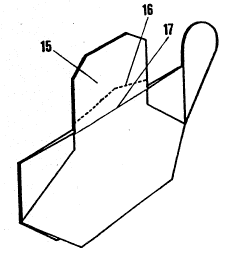
~`~ detachabIe edge or some flaps 15 as in Drawing No. 3, where
such a detachable edye str~p can also form a cleat, thus
preventing the distribution of loose parts to the cup. The
detacha~le edg~ or ~eal 15 is torn off along the perforated
lin~ 16. A8 lo~g a~s the seal lS has not been torn off, the user
-~ ha6 definiti~e visual proof that the cup is unu~ed. After the
seal has been detached, two flaps along the edge of the openin~
of the cup are retained, inasmuch as the formerly protected
insides of the flaps are folded along the folding line 17, by
which means the user can be sure that the contac~ surface for
the lips of the mouth is absolutely clean, even if the cup ha~
2130S~7 :-
WO93/16926 PCT/DK93/0~3
been stored in conditions that could entail that the outsidesof the cup are covered with dust or other particles.
A special embodiment of the cup as specified in accordance with
the invention is to furnish the cup with angled guides on each
side of the folding lines 4 and S as in Drawing No. 2. In the
open position of the cup these guides form brackets for the
introduction of a flat cleat over the end of the guides. This
~; locks the cup more stably in open position, while the shape of
the cleat at the surface;heips to shape the opening of the cup.
This gives greater rfgidLty and stability to the cylinder of
the cup, while the cleat helps to prevent accidents with the
cup where the cup could be made to collapse before the contents
were used and the contents would be pressed out over the rim of
the cup.
Claims 3-5 specify embodiments of the invention which give the
cup a smoother transition from the closed to the open position,
which counteracts leakage in carton pasted with plastic film,
which could otherwi~se be deformed such that the plastic coating
could be torn and the oup;would leak. It has emerged that if
~ ~ one adds three identical triangles 7 with folding lines within,~ ; as shown in Drawings no.~2 and~No. 5, the centre line 11 in the
erect state virtua~lly rolls~out through the perpendiculars of
25 ~ the said triangles~ while the points 12 are displaced in stages
until the straight centre line reaches the points 6, making the
centre line a straight~line. This effect takes place almost
automatically, as~a~result of the spring-like action of the
sides triggered by the folding of the cup. The undulating
folding lines specified in Claim 5 will in addition enhance the
~aid automatic effect, inasmuch as the undulating folding lines
will be forced more~;closely together by the opening and closing
of the cup and will thus have a spring-like, reinforcing effect
on the said action.
Claim 6 concerns a particularly important embodiment of the
invention, inasmuch as it has proved possible to cut out or
21~0~47
WO93/16926 . PCT/DK93/00043
punch out the cup in one piece without joints from a plane
sheet o~ length of cardboard, carton or plastic sheet which,
besides the folding lines specified in Claim 1, is also embod-
ied with the folding lines 18 as in Drawing No. 5. During the
S acsembly of the cup, certain tabs 21 and 22 as in Drawing No. 6
arise, where the insides of the tabs are folded around the said
: lines 18. The edges of the said tabs are flush with the rim of
the cup when the cup is assembled, rendering it waterproof if
the surface of the material, or at least the inside surface, is
proof against the contents which the cup is meant to contain.
The tabs are bent back around the outside of the cylinder and
may~form a handle consisting of the two tabs 21 at one end of
the cup, and at the other end of the cup the points of the tabs
22 o~erlap each other inside and under the bent-~ack flap 24,
lS which is bent down over the tabs and fixes these in position
without any gluing or welding of the material. The ~lap 23 has
~ a similar function, but :is further furnished with a slot which
:~ ~ is moved down over the parts of the tabs 21 which form the
handle, thus fixing the~said tabs in a stable assembly. When
~: 20 the cup is assembled as~described, it is folded as specified in
Claim l.: The assembled:~and:folded cup of this type appears in
:~ Draw ng No. 4. ~ ~ ~
Claim 7 specifies.~a method:of introducing a cleat which fixes
~; 25~: : the cup in its open~position as described in Claim 2, inasmuch
as the~cup, as in Claim~6, has a naturally-formed space for the
: introduction of the:~cle~at between the tabs 21 and 22 and the
outside of the cup at.the outer surface of the cylinder.
Claim B concerns an embodiment of the cup as in Claims 6 and 7,
where the cleat forms a permanent part of the sides of the cup,
: : inasmuch as the cleat consists of a part of the flaps 15, which
are detached when~:the seal of the cup is broken as described in
Claim 1, but where Claim 8 specifies that the cleat consists of
two congruent tabs which are permanent parts of the sheet or
length of material from which the cup is cut or punched out,
inasmuch as the two tabs are glued or welded together above the
21305~7
t
WO93/16926 PCT~DK93!0004
perforated tearing line when the cup is assembled as shown in
Drawing No. 3.
.
The cup as specified in Claim 9 is particularly suitable for
S informative purpos~s and for messages of a promotional nature,
inasmuch as patterns, sy~bols, texts and pictures may be
applied to the ~up by means of already-known printing methods
such as o~fset or screen printing. The print is applied to the
plane she~t or lengths before or after the cups are cut or
punched from it~ and before the cups are assembled, or one may
choose to apply the print after the assembly of the cups, when
the sides of the cups are completely flat in the collapsed
position of the cups a~d thus form a good surface for the
application of th~ print.
In use, the two curved sides of the open cup offer wide visual
exposure surfaces which can be viewed without turning the cup.
These exposure surfaces are particularly easy to view when the
user receives the cup in collapsed form.
The ~up is therefore in addition a new medium for advertise-
ments and other messages. Not least when the embodiment of the
:~ invention i8 a drinking cup, the cup can be used as a quick,
heap means of contact with many people, inaæmuch as the cup
: 25 can further be distributed:in ordinary postal envelopes.
.
The in~ention i8 explained in more detail in the following with
references to the ~rawings, where
,
Fig. 1 ~hows a preferred embodiment of a drinking
cup as fipe~ified in accordance with this invention,
manufactured in a transparent plastic material.
Fi~. 2 ~hows a ~imilar cup, but in an opaque mate-
rial, furni~hed with angled guides which allow for
the introduction of ~ariously-ormed cleats.
2130 j~7
WO93/16926 PCT/DK93/00043
11
Fig. 3 shows a similar cup which may be manufac~
tured by cutting or punching out from a sheet or
leng~h of cardboard, carton or plastic, ina~much as
the cl~at is in one piece with the cup on the
sheet.
Fig. 4 shows a cup corresponding to the cup in Fig.
3, but with the cleat detached along a perforated
liné, after which the cup can be opened.
1~
Fig. 6 shows the cup as shown in Figs. 3 and 4 as
it looks on ~he sheet or length of ma~erial after
cutting or punching out.
lS Fig. 6 ~hows the cup as in Figs. 3-5, during a~sem-
bly into an open cup.
Fi~. 1 sho~s the cup in open position after the discontinuous
~eal along the ri~ of the cup has been broken. The cup is
in~ection-moulded or vacuum-moulded in a transparent plastic
; matexial, and the fslding lines 4, 5, 8 and 11 are stamped in
~ the mat~rial a~ V-shaped grooves. The ~ides 2 and 3 of the cup
: ~may be thicker along the opening of the cup than the other
~: ~ur~aces o~ the ¢up, which will enhance the spring-like fea-
25 ture~:of the ~ides in ~he open position of the cup. The points
~: 6 and 12 are inter~ection poin~s of the said folding lines.
~: Fig. 2 ~ho~ a gimilar injection-moulded cup, but in an opaque
makerial ~haped with angled guides on each side of the folding
30 lines 4 and 5. These guides have longitudinal openings facin~
ea~h other, ~uch that a cleat may be introduced o~er the en~ o
the angled guide~ at the bottom of the cup. The upper cl~at
shown in the drawing has a straight surface, which gi~es the
cup a special curved opening. The lower cleat is slightly
angled around its axis of s~mmetry, inasmuch as the shape o
the cleat foll~ws th natural open shape of the cup oYer the
~nds at the folding lines 4 and 5. Th~ triangles 7 are formed
2130~7
t . , ' ':'.'`~
WO93/16926 PCT/DK93/0
12
with three isosceles trianglas within them along the folding
lines, facilitating a smoother transition from the open form of
the cup ~o its collapsed position, such that the form with the
triangle~ 7 is particularly applicable for manufacturing the
cup from a particularly stiff material.
Figs. 3 and 4 shQw a cup in collapsed position, the cup being
cut or punched from a sheet or length of cardboard, carton or
plasti~ sheet. The cup as in Fig. 3 is furnished with a cleat
which is in one piece wi~h the sides 2 and 3 of the cup,
inasmuch as the cleat can be detached along a perforated line
16, leaving cer~ain flaps 15, which ~an be seen in Fig. 4, and
which are bent back along the folding lines 17 on both sides 2
and 3, whereby the clean insides of t~e flaps are turned
outwards and thus form a point of contact for the lips of the
mouth when the use drinks from the cup. As can be seen in Fig.
4, the centre line 11 runs in the erect position between the
:~: aforementioned intersection points 6, inasmuch as the centre
line thu~ divides the aforemen*ioned triangles 7 and the bottom
of the cup a~ described above.
Fig. 5 shows the cut or punched cup in the unassembled s$ate,
with the aforementioned folding lines of the cup marked off on
the ~heet along with the folding lines 18 peculiar t9 the
: 25 invention as in Fig. 5, aro~lnd which the areas 19 and 20 shown
.
in the figure are bent into tabs which run along the outside
: ~ur~aces of the cup in the assembled state of the cup, inasmuch
as the edges of the tabs are flush with the rim sf the cup.
The two part~ of the flaps 15 of the cup which are above the
broken line, and which form a cleat, will be glued or welded
together into one cleat. The aforementioned triangles 7 are
furni~hed on the sheet with folding lines which run parallel
with the base lines of the triangles, which gives the cup a
smoother tran~ition from the closed to the open position. Also
indicated on the æheet are the two lugs which form the handle
of the cup, as are the flaps 23 and 24 as in ~ig. 6.
i
.
2130~7
W093/16926 PCT/DK93/~N~3
13
Fig. 6 shows the cup as in Fig~ S during assembly, but without
the flaps 15 shown in Fig. S. It can be seen that the tabs 21
and 22 are flush with the rim of the cup when open, which makes
the cup waterproof, inasmuch as the liquid in the cup will only
run out into the said tabs without running over the,edge of the
tabs, ~ince the liquid level in the cup will always lie below
tbe edges of the tabs. The flaps 23 and 24 are seen before they
are turned down around the outside of the cylinder of the cup,
thus fixing the tabs 21 and 22 in against the outer surface of
the cylinder of the cup. The flap 23 is embodied with a cut or
punched sl~t through which the two parts of the cup which form
the handle are inserted when the flap is turned down over the
tabs 21, locking the~handle of the cup in a stable position.
, ~ ~
~: ,
,
~: :
~:
'; .
:~: :~::
'::