Note: Descriptions are shown in the official language in which they were submitted.
1- 2130614
BACKGROUND OF THE INVENTION
Field of the Invention
The present invention relates to a vertical
milling machine comprising a first milling part and a
second milling part.
Description of Related Arts
Heretofore, there have been known milling
machines of the type that two or more milling rolls or
whitening rolls are mounted on one main shaft. For
example, U.S. Pat. No. 3,485,280 discloses a horizontal
milling machine 81 shown in Fig. 5. In this milling
machine 81, starting from the right and going to the
left in Fig. 5, a screw roll 83, an abrasive milling or
whitening roll 84, an intermediate screw roll 85 and a
friction type milling roll 86 are mounted on a
horizontal main shaft 82 in order. Around the abrasive
milling roll 84 is disposed an annular wire mesh bran
discharge member or bran-removing, perforated
cylindrical body 87 which cooperates with the abrasive
milling roll 84 to form an annular abrasive milling
chamber 88, while around the friction type milling roll
86 is disposed an annular wire mesh bran discharge
member or bran-removing, perforated cylindrical body 89
which cooperates with the friction type milling roll 86
to form an annular friction milling chamber 90. The
- 2 - 213061~
abrasive milling chamber 88 is communicated at one end
(right end in Fig. 53 thereof with a supply port 91 of
the milling machine 81, while the friction milling
chamber 90 is communicated at one end (left end in Fig.
5) thereof with a discharge port 92 of the milling
machine 81. A feed hopper 93 is provided at the supply
port 91, and a resistance board 94 is provided at the
discharge port 92. To the resistance board 94 is
attached a weight 95 for adjusting pressing force
exerted thereby.
According to the conventional milling machine
81 shown in Fig. 5, milling is performed in the
following manner.
As grains to be milled are supplied from the
feed hopper 93 to the vicinity of the screw roll 83
through the supply port 91, the grains are forwarded
generally horizontally by the screw roll 83 and, in the
abrasive milling chamber 88, milled under the milling or
whitening action by the abrasive milling roll 84 which
is being rotated. The grains having been milled in the
abrasive milling chamber 88 are forwarded to the
friction milling chamber 90 by the intermediate screw
roll 85 and, in the friction milling chamber 90, milled
still more under the milling action by the friction type
milling roll 86 which is being rotated. The grains
having been milled in the friction milling chamber 90
are discharged through the discharge port 92 to the
outside of the machine against the pressing force of the
- 3 ~ 213061~
resistance board 94.
In the conventional milling machine 81
described above, resistance board is provided only at
the discharge port 92 of the friction milling part
constituting the second milling part, while a discharge
part of the abrasive milling part constituting the first
milling part is substantially completely communicated
with a supply part of the friction milling part
constituting the second milling part, and therefore, it
is impossible to adjust the degrees of milling or
whitening in two milling parts independently.
Further, in the conventional horizontal
milling machine 81 described above, since the abrasive
milling roll 84 and the friction type milling roll 86
are mounted on one shaft 82, a diameter of the abrasive
milling roll 84 is made larger than that of the friction
type milling roll 86. This is for the purpose of making
peripheral speed of the abrasive milling roll 84 larger
than that of the friction type milling roll 86.
However, in the above horizontal milling machine, it is
structurally difficult to provide uniform contact of the
grains with the abrasive milling roll over the whole
circumference thereof when the diameter of the abrasive
milling roll is increased, and the limit of its diameter
is about 30 cm. Accordingly, there is a limit in
increase of the size of the machine 81, making it
difficult to enhance milling capacity drastically.
4 2l3061~
SUMMARY OF THE INVENTION
The present invention aims to solve at least a
part of the above-described disadvantages of the
conventional milling machine.
An object of the present invention is to
provide a milling machine in which degree of milling or
whitening of grain can be easily adjusted.
Another object of the present invention is to
provide a milling machine in which milling roll can be
increased in size and milling capacity can be enhanced.
According to the present invention, at least a
part of the above object can be achieved by a vertical
milling machine comprising: a first milling part; and a
second milling part situated under said first milling
part, the first and second milling parts having or
sharing a common main shaft extending vertically,
wherein the first milling part has a supply part of
grain on an upper end side thereof and a discharge part
of grain having been milled in said first milling part
on a lower end side thereof, the second milling part has
a supply part of grain to be milled in said second
milling part on a lower end side thereof and a discharge
part of grain having been milled in said second milling
part on an upper end side thereof, and the grain
discharge part of the first milling part is communicated
with the grain supply part of the second milling part
through a grain transfer passage extending therebetween.
- 5 213U614
Since the milling machine of the present
invention is a vertical milling machine, size of the
milling roll constituting the milling part can be
increased easily.
Further, in the milling machine of the
invention, since the grain supply part of the lower
second milling part is provided on the lower end side of
the second milling part, or since the grain transfer
passage communicates the grain discharge part of the
first milling part with the grain supply part of the
second milling part on the lower end side thereof,
resistance means for adjusting the degree of milling
(degree of whitening) in the first milling part can be
disposed in the grain transfer passage (including the
grain discharge part of the first milling part), and
accordingly, the degrees of milling (degrees of
whitening) in the first and second milling parts can be
individually adjusted without difficulty.
More specifically, grain supplied to the grain
supply part at the upper end of the first milling part
flows downward to the grain discharge part at the lower
end thereof as being milled in the first milling part,
and is then supplied from the grain discharge part of
the first milling part to the grain supply part of the
second milling part. Since the grain supply part of the
second milling part situated under the first milling
part is provided at the lower end of the second milling
part, it is possible to have a sufficient length of
- 6 - 213061~
. .
grain transfer passage between the grain discharge part
of the first milling part and the grain supply part of
the second milling part, and an enough space can be
provided at for example the upper end of the grain
transfer passage or at the grain discharge part of the
first milling part, and accordingly, by disposing in
this space resistance means for adjusting pressing force
applied to the grain in the first milling part, the
degree of milling in the first milling part can be
adjusted. Grain sent to the grain supply part of the
second milling part is sent upwards as being milled in
the second milling part and discharged from the grain
discharge part at the upper end of the second milling
part. The degree of milling of grain in the second
milling part can be adjusted by disposing resistance
means for adjusting pressing force applied to the grain
in the second milling part at the grain discharge part
at the upper end of the second milling part.
Further, according to the milling machine of
the present invention, since a plurality of milling
parts are disposed in or on one milling machine frame,
i.e. one frame, installation area of the whole milling
machine can be reduced and manufacturing cost of the
milling machine can be reduced.
In the milling machine of the present
invention, it is preferred that the first milling part
is provided at the grain discharge part thereof with a
first resistance means for adjusting degree of milling
_ 7 _ 2130614
of grain in the first milling part, and the second
milling part is provided at the grain discharge part
thereof with a second resistance means for adjusting
degree of milling of grain in the second milling part.
In this case, since the degrees of milling in
the first and second milling parts can be individually
adjusted without difficulty by the first and second
resistance means, respectively, milling of grain can be
performed in the condition that the milling machine is
optimized to make the first and second milling parts
fulfil their respective milling (whitening) functions at
the best.
According to a preferred embodiment of the
present invention, the first milling part comprises a
first milling roll mounted on an upper part of the main
shaft and a first bran-removing, perforated generally
cylindrical body cooperating with the first milling roll
to form a first milling chamber, and the second milling
part comprises a second milling roll mounted on a lower
part of the main shaft and a second bran-removing,
perforated generally cylindrical body cooperating with
the second milling roll to form a second milling
chamber.
Grain supplied from the grain supply part of
the first milling part to the first milling chamber is
milled by the milling (whitening) action of the rotating
first milling roll as it is sent downwards in the first
- 8 - 213061~
-
milling chamber. The grain thus milled is further sent
from the grain discharge part of the first milling part
to the grain supply part of the second milling part
through the grain transfer passage and, in the second
milling chamber, milled by the milling action of the
rotating second milling roll as it is sent upwards, and
thereafter, discharged from the grain discharge part at
the upper end of the second milling chamber to the
outside of the milling machine. Powdered substance such
as bran produced at the time of milling (whitening)
grain in the first and second milling chambers is
discharged through perforations of the first and second
bran-removing, perforated cylindrical bodies,
respectively, to the outside of the milling chambers so
as to be collected.
According to a preferred embodiment of the
present invention, the first milling roll is composed of
one of abrasive milling roll and friction milling roll,
and the second milling roll is composed of one of
abrasive milling roll and friction milling roll.
In case that the milling roll is composed of
abrasive milling roll, grain is milled by abrasive
milling (whitening) action of the rotating abrasive
milling roll with respect to the grain, while in case
that the milling roll is composed of friction type
milling roll, grain is milled by friction milling
(whitening) action of the rotating friction type milling
roll with respect to the grain. Combination of abrasive
9 2130614
milling roll and/or friction milling roll is selected in
accordance with various factors such as kind and surface
layer condition of grain to be milled, and condition of
grain to be obtained by milling.
According to a preferred embodiment of the
invention, the grain transfer passage extends generally
vertically downwards from the grain discharge part of
the first milling part to the grain supply part of the
second milling part
The foregoing and other objects, features and
advantages of the invention will be made more apparent
from description hereafter of preferred embodiments
referring to attached drawings.
BRIEF DESCRIPTION OF DRAWINGS
Fig. 1 is a vertical sectional view of a
vertical milling machine according to a preferred
embodiment of the invention;
Fig. 2 is an enlarged sectional view of a part
of Fig. 1, and corresponding to a section along a line
II-II of Fig. 3;
Fig. 3 is a cross-sectional view of Fig. 2
along a line III-III of Fig. 2;
Fig. 4 is a diagrammatic view of possible
alternatives of the first and second milling parts of
the vertical milling machine; and
Fig. 5 is a sectional view of a conventional
horizontal milling machine.
- 10- 213061~ -
DETAILED DESCRIPTION OF PREFERRED EMBODIMENTS
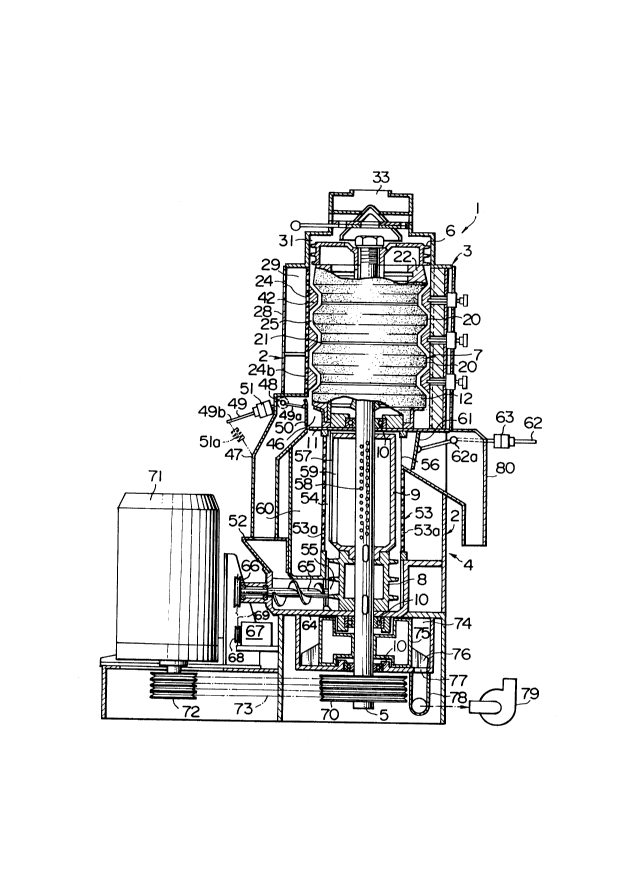
In Figs. 1 - 3, a vertical milling machine 1
comprises an abrasive milling part 3 as the first
milling part disposed in an upper part of a machine
frame 2 and a friction milling part 4 as the second
milling part disposed in a lower part of the machine
frame 2. A hollow main shaft 5 with an opening at its
lower end is rotatably attached to the machine frame 2
through bearing portions 10, 10, 10. The main shaft 5
extends vertically. A screw roll 6 and an abrasive
milling roll 7 as the first milling roll are mounted on
an upper part of the main shaft 5, while a screw roll 8
and a friction type milling roll 9 as the second milling
roll are mounted on a lower part of the main shaft 5.
In this milling machine 1, since a plurality
of milling parts 3, 4 are formed in one machine frame 2,
area for installation of the whole milling machine can
be reduced and manufacturing cost thereof can be reduced
significantlY-
First, description will be given of detailedconstruction of the abrasive milling part 3. In Fig. 1,
a rotary bottom member 11 is fixed to the main shaft 5,
and a lowermost abrasive milling or whitening roll
element 12 fitted on the main shaft 5 is set on and
fixed to the rotary bottom member 11 through a setting
ring 13. The lowermost abrasive milling roll element 12
comprises a large diameter portion 12a, a small diameter
- 11 , 2l3o6l~
-
portion 12b and an upper inclined portion 12c as shown
in Fig. 2. The lowermost abrasive milling roll element
12 is supported at a side step portion thereof by the
setting ring 13 with flange portion as shown in Figs. 1
and 2. An inner peripheral wall of the setting ring 13
is fitted on a small diameter portion of the lowermost
abrasive milling roll element 12.
The lowermost abrasive milling roll element 12
comprises an inner support part 12e made of metal and an
outer abrasive part 12f made of abrasive emery
particles. The inner support part 12e comprises a boss
portion 16 having therein round holes 17 and a ~lurality
of arms 14 between which openings 15 are formed. The
holes 17 of the boss portion 16 are communicated with
blast air holes 18 of the hollow main shaft 5 on which
the boss portion 16 is fitted.
A collar 19 fitted on the shaft 5 is set on
the lowermost abrasive milling roll element 12. On the
collar 19 is set on a boss portion 16 of an intermediate
abrasive milling roll element 20 having on the whole
almost the same structure as the lowermost abrasive
milling roll element 12. In the intermediate abrasive
milling roll element 20 as well, the boss portion 16 is
formed with round holes 17 communicating with the blast
air holes 18 of the hollow main shaft 5, and openings 15
are formed between arms 14 thereof (Figs. 2 and 3). The
intermediate abrasive milling roll element 20, more
specifically, an outer abrasive part 20f thereof
- 12 - 21306
..
comprises a large diameter portion 20a, a small diameter
portion 20b, a lower inclined portion 20d therebetween
and a downwardly divergent upper inclined portion 20c
formed above the large diameter portion 20a. Between
the lower end of the small diameter portion 20b of the
intermediate abrasive milling roll element 20 and the
upper end of the lowermost abrasive milling roll element
12 is formed a gap 21 for jet air.
On the boss portion 16 of the intermediate
abrasive milling roll element 20 is set another collar
19 fitted on the shaft 5. On this collar 19 is set a
boss portion 16 of another intermediate abrasive milling
roll element 20 fitted on the shaft 5. This
intermediate abrasive milling roll element 20 has the
same structure as the intermediate abrasive milling roll
element 20 on the lowermost abrasive milling roll
element 12. Namely, this intermediate abrasive milling
roll element 20, more specifically, an outer abrasive
part 20f thereof comprises a large diameter portion 20a,
a small diameter portion 20b, an upper inclined portion
20c and a lower inclined portion 20d, and a gap 21 for
jet air is formed between the lower end of this small
diameter portion 20b and the upper end of the lower
intermediate abrasive milling roll element 20 on the
lowermost abrasive milling roll element 12. On the boss
portion 16 of the upper intermediate abrasive milling
roll element 20 is set still another collar 19 fitted on
- 13 - 21 3~614
-
the shaft 5. On this collar 19 is set a boss portion 16
of an uppermost abrasive milling roll element 22 fitted
on the shaft 5.
In this embodiment, two intermediate abrasive
milling roll elements 20 are equipped, and however, the
number of the intermediate abrasive milling roll
elements 20 to be equipped through collar or spacer 19
may be one or not smaller than three. Further, under
certain circumstances, the intermediate abrasive milling
roll element 20 may be dispensed with.
The uppermost abrasive milling roll element 22
comprises an inner support part 22e made of metal and an
outer abrasive part 22f made of abrasive emery
particles. The inner support part 22e comprises the
boss portion 16 having round holes 17 and a plurality of
arms 14 between which openings 15 are formed. The holes
17 of the boss portion 16 are communicated with the
blast air holes 18 of the hollow main shaft 5 formed in
the vicinity of the upper end thereof, on which shaft 5
is fitted the boss portion 16. The outer abrasive part
22f of the uppermost abrasive milling roll element 22
comprises a downwardly slightly divergent or circular
truncated cone-shaped large diameter portion 22a, a
small diameter portion 22b and a lower inclined portion
22d between the large diameter portion 22a and the small
diameter portion 22b, and a gap 21 for jet air is formed
between the upper end of the small diameter portion 22b
~ - 14 ~ 21 30614
-
and the upper end of the another intermediate abrasive
milling roll element 20 situated just therebelow.
On the boss portion 16 of the uppermost
abrasive milling roll element 22 is set a boss portion
of the aforesaid bottomless hollow screw roll 6 fitted
on the shaft 5. The screw roll 6 is formed on the outer
periphery thereof with a feed screw 6a. The screw roll
6 is pressed on and fixed to the uppermost abrasive
milling roll element 22 by means of a bolt 23 screwed to
the upper end of the hollow main shaft 5.
Around the large diameter portions 12a, 2Oa,
22a of the lowermost abrasive milling roll element 12,
intermediate abrasive milling roll elements 20 and
uppermost abrasive milling roll element 22 is disposed a
bran-removing, generally cylindrical perforated body 24
leaving a small space between them, so that an abrasive
milling chamber 25 as the first milling chamber is
formed between the bran-removing cylindrical perforated
body 24 and the abrasive milling roll elements 12, 20,
22 (Figs. 2 and 3). More specifically, the bran-
removing, generally cylindrical perforated body 24
comprises four divided parts 24d each supported at both
side edges thereof by associated two of four stanchions
26 provided upright around the abrasive milling roll
elements 12, 20, 22. Each stanchion 26 is covered with
a stanchion cover 27 of a U-letter form cross-section.
A bran-removing chamber cover 28 of an arcuate cross-
~ - 15 - 213061~
.
section is disposed between each circumferentially
adjacent stanchion covers 27, 27, the cover(s) 28
cooperating with corresponding bran-removing cylindrical
perforated body 24 or divided parts 24d thereof to form
a bran-removing chamber 29.
A diameter of the large diameter portions 12a,
20a, 22a of the abrasive milling roll elements 12, 20,
22 which depends on amount of grains to be milled per
unit period of time is about 40-50 cm for about 8
tons/hr. Since the milling machine 1 of this embodiment
is of the vertical shaft type that the main shaft 5
extends vertically, it is possible to increase the outer
diameter of the abrasive milling roll 7 or the elements
thereof, as compared with the case of the horizontal
type machine.
On the stanchions 26 is set on and fixed to a
feed cylinder 30 surrounding the screw roll 6 and having
a supply port 31 at the upper end thereof. A hopper
cylinder 32 having a charging port 33 at the upper end
thereof is fixed to the upper end of the supply port 31.
In the hopper cylinder 32 is provided a grain feed
amount regulating mechanism 34 comprising a fixed plate
34a with a plurality of openings and a rotary plate 34b
with a plurality of openings and rotatable by a
regulating lever 35. An opening 36 is formed through
the central portion of the fixed plate 34a and rotary
plate 34b. A hollow bottomless conical upper guide
member 37 is disposed above the opening 36, while a
- 16 - 2130614
-
lower guide member 38 of a circular truncated cone shape
is disposed below the opening 36. Further, induction
pipes 40 are provided for taking atmospheric air into
the upper guide member 37 through a plurality of air
inlet ports 39 formed circumferentially equidistantly in
a peripheral wall of the hopper cylinder 32. The screw
roll 6 is formed in an upper wall surface thereof with
vent holes 41 in the positions below the lower guide
member 38.
In addition, the bran-removing cylindrical
perforated body 24 is provided on an inner peripheral
surface thereof with resistance rings 42a, 42b, 42c.
More specifically, the resistance ring 42a is so
provided as to protrude into a trough portion 43a formed
by the lower inclined portion 22d and small diameter
portion 22b of the uppermost abrasive milling roll
element 22 and the upper inclined portion 20c of the
intermediate abrasive milling roll element 20 situated
just below the element 22, the resistance ring 42b is so
provided as to protrude into a trough portion 43b formed
by the lower inclined portion 20d and small diameter
portion 20b of the intermediate abrasive milling roll
element 20 and the upper inclined portion 20c of the
other intermediate abrasive milling roll element 20 just
therebelow, and the resistance ring 42c is so provided
as to protrude into a trough portion 43c formed by the
lower inclined portion 20d and small diameter portion
- 17 _ 21 3061ll
-
20b of the lower intermediate abrasive milling roll
element 20 and the upper inclined portion 12c of the
lowermost abrasive milling roll element 12.
As is obvious from Fig. 2, the sectional shape
of the resistance rings 42a to c is nearly similar to
that of the trough portions 43a to c, and the milling
chamber 25 formed between the resistance rings 42a to c
and the trough portions 43a to c becomes a meandering
milling chamber 25a meandering from top to bottom.
Each of the resistance rings 42a to c is
pressed on and fixed to the inner peripheral surface of
the bran-removing cylindrical perforated body 24 by knob
bolts 45 inserted in through-holes 44 of the respective
stanchions 26. Since an inner diameter A of the hole 44
is considerably larger than the diameter of the knob
bolt 45, the knob bolt 45 is vertically displaceable
with respect to the stanchion 26 by an amount
corresponding to this difference in diameter, making it
possible to adjust vertical attaching positions of the
resistance rings 42a to c and adjust a resistance with
respect to the flow of grains in the meandering milling
chamber 25a.
A discharge port 46 is formed at the lower end
of the abrasive milling chamber 25, and a discharge
chute 47 is provided below the discharge port 46. A
horizontal shaft 48 is attached to the discharge chute
47, and a weighted lever 49 comprising arm portions 49a,
49b is attached to the horizontal shaft 48 so as to be
- 18 _ 21 3061~
..
rotatable about the horizontal shaft 48 with respect to
the discharge chute 47. A resistance board 50 capable
of closing the discharge port 46 is rotatably attached
to a distal end of the arm portion 49a of the weighted
lever 49, while a weight 51 is set on the arm portion
49b of the weighted lever 49 so as to be displaceable in
the longitudinal direction of the arm portion 49b. In
this embodiment, the resistance means capable of
adjusting the pressing force applied to the grains in
the milling chamber 25 and hence the degree of milling
of the grains in the abrasive milling chamber 25
comprises the shaft 48, weighted lever 49, resistance
board 50 and weight 51. Meanwhile, the grain discharge
part comprises the discharge port 46 and discharge chute
47 which also serves as the transfer passage. The
discharge chute 47 is communicated with a supply chute
52 of a friction milling part 4. Means for adjusting
the pressing force applied to the resistance board 50
may be any force adjusting means in place of a
~0 combination of the lever 49 and displaceable weight 51.
Further, as shown by imaginary lines in Fig.
1, an elastic means 51a such as tension or expansion
spring may be provided between the weighted lever 49 and
the discharge chute 47. Under certain circumstances,
elastic force of the elastic means 51a, such as modulus
of elasticity or elastic coefficient may be made
adjustable. For example, in the latter case, the weight
may be dispensed with.
213061~
-- 19 -
-
Next, description will be given of the
friction milling part as second milling part. The
friction milling part 4 comprises the screw roll 8
mounted on the hollow main shaft 5 in the vicinity of
the lower end thereof, the friction type milling roll 9
mounted on a lower part of the hollow main shaft 5 to be
situated above the screw roll 8, and a bran-removing
cylindrical perforated body 53 extending vertically
around the friction type milling roll 9 so as to form a
friction milling chamber 54. The friction milling
chamber 54 is communicated with a supply port 55 at a
lower end thereof and with a discharge port 56
approximately at an upper end thereof. The friction
type milling roll 9 stirs the grains in the friction
milling chamber 54 by means of a stirring projection 57
provided thereto, making the grains rub each other. The
hollow main shaft 5 is formed with a large number of
vent holes 58 which are communicated with the friction
milling chamber 54 and a bran-removing chamber 60
through blast air holes 59 of the friction type milling
roll 9. The friction milling machine itself has been
known as disclosed in for example U.S. Pat. No.
4,843,957, which is incorporated herein by this
reference thereto.
A resistance board 61 for adjusting the degree
of milling of grain is provided at the discharge port
56. By adjusting the position of a weight 63 set on a
213061~
-- _
weighted lever 62 rotatable about a horizontal shaft 62a
like the weighted lever 49, the degree of milling of the
grains in the friction milling chamber 54 can be
adjusted. A discharge chute 80 is communicated with the
discharge port 56, while a conveyor trough 64 is
communicated with the supply port 55. A horizontally
extending screw conveyor 65 is provided in the conveyor
trough 64, and a pulley 66 is attached to one end of the
conveyor 65. Between the pulley 66 and a pulley 68
attached to an electric motor 67 is stretched a belt 69,
while between a pulley 70 attached to the hollow main
shaft 5 and a pulley 72 attached to a main electric
motor 71 is stretched a belt 73.
Below the bran-removing chamber 60 is formed a
bran-collecting chamber 74 communicated with the bran-
removing chamber 60. A plurality of scraping blades 76
formed on an outer peripheral surface of a blade setting
cylinder 75 mounted on the main shaft 5 are positioned
in the bran-collecting chamber 74. A bran discharge
port 77 is formed in the bottom of the bran-collecting
chamber 74, and a bran-collecting fan 79 is connected to
a distal end of an exhaust pipe 78 extending from the
bran discharge port 77. The bran-removing chamber 60 of
the friction milling part 4 is communicated with the
bran-removing chamber 29 of the abrasive milling part 3,
and the bran-collecting chamber 74 is communicated with
the bran-removing chamber 29 through the bran-removing
chamber 60.
- 21 _ 21 3061 ~
-
In the milling machine 1 of this embodiment,
since the supply port 55 of the friction milling part 4
as the lower and second milling part is provided at the
lower end of the friction milling part 4 , it is easy to
provide at the discharge port 46 of the abrasive milling
part 3 as the upper and first milling part a space or
room large enough to attach the resistance means 46 to
51 for adjusting the degree of milling of the grains in
the abrasive milling part 3. Accordingly, the degree of
milling or whitening of the grains in the abrasive
milling part 3 can be adjusted by the resistance means
independently of the degree of milling or whitening of
the grains in the friction milling part 4, thereby
facilitating fine or delicate adjustment of the degree
of whitening of grain.
Now, operation of the vertical milling machine
1 according to a preferred embodiment of the present
invention, which is constructed as described above, will
be described taking a case of milling rice grain as an
example of cereal grain. The cereal grain to be milled
may be wheat grain or other cereal grain in place of
rice grain.
Prior to commencement of milling, vertical
positions of the resistance members 42a to c are
adjusted by making use of the knob bolts 45 to adjust
the resistance with respect to the flown-down of the
rice grains. Further, by adjusting the position of the
weight 51 on the arm portion 49b of the lever 49, the
213061~
- 22 -
force with which the resistance board 50 attached to the
distal end of the arm portion 49a of the lever 49 closes
the discharge port 46 or the pressing force which the
resistance board 50 should apply to the rice grains at
the discharge port 46, that is, the pressure applied to
the rice grains in the abrasive milling chamber 25 or
the condition of the rice grains filled in the abrasive
milling chamber 25 or, in other words, the degree of
milling or whitening is adjusted. In the same manner,
by adjusting the position of the weight 63 on the lever
62, the force with which the resistance board 61
attached to the distal end of the lever 62 closes the
discharge port 56 or the pressing force which the
resistance board 61 should apply to the rice grains at
the discharge port 56, that is, the pressure applied to
the rice grains in the friction milling chamber 54 or
the condition of the rice grains filled in the friction
milling chamber 54 or, in other words, the degree of
whitening is adjusted independently of the degree of
whitening in the abrasive milling chamber 25. If
desired, the respective pressing forces of the
resistance boards 50, 61 or the respective degrees of
whitening in the abrasive milling chamber 25 and the
friction milling chamber 54 may be adjusted by the
weights 51, 63 during the milling or whitening.
As the main motor 71 is started, the screw
roll 6, the abrasive milling roll 7, the screw roll 8
213061~
- 23 -
and the friction type milling roll 9 are rotated through
the hollow main shaft 5 and, as the motor 67 is started,
the screw conveyor 65 is rotated. Further, the bran-
collecting fan 79 is started.
Raw material rice grains supplied through a
chute (not shown) to the charging port 33 or the rice
grains to be milled by the milling machine 1 flow down
as being dispersed uniformly in the circumferential
direction by the upper guide member 37 and fall into the
supply port 31 at an appropriate flow rate adjusted by
the regulating lever 35.
The rice grains having fallen in the supply
port 31 are fed successively into the abrasive milling
chamber 25 by means of the screw roll 6. The rice
grains in the abrasive milling chamber 25 actively flow,
that is, revolve (rotate around the main shaft 5) and
roll or rotates under a relatively low pressure or under
the condition that they push to each other with a
relatively small pressing force, while being rubbed with
the peripheral surfaces of the uppermost, intermediate
and lowermost abrasive milling roll elements 22, 20, 20
and 12 of the abrasive milling roll 7, so that surface
layers thereof are abraded. More specifically, while
the rice grains flow down from the downwardly slightly
divergent upper inclined portion 22a of the uppermost
abrasive milling roll element 22 through the upper part
of the meandering milling chamber 25a formed by the
trough portion 43a and the resistance ring 42a, they
2130614
- 24 -
repeat rolling and revolving actively, resulting in that
the surface of each rice grain is abraded substantially
all over. When the rice grains pass through the
meandering milling chamber 25a, they move from around
the bran-removing cylindrical perforated body 24 toward
the abrasive milling roll 7 or, conversely, from around
the abrasive milling roll 7 toward the bran-removing
cylindrical perforated body 24, and accordingly, the
rice grains in the milling chamber 25 can have increased
chances of contact with the peripheral surface of the
milling roll 7.
In this way, the rice grains flow down through
the upper part of the meandering milling chamber 25a
defined by the trough portion 43a and the resistance
ring 42a while stagnating temperately. The extent of
stagnation, the average flowing-down speed and the like
depend on the magnitude of the pressing force applied by
the resistance board 50. In a part of the abrasive
milling chamber 25, defined between the large diameter
portion 20a of the upper intermediate abrasive milling
roll element 20 and the bran-removing cylindrical
perforated body 24, the rice grains are subjected to the
milling action by the large diameter portion 20a, while
bran having been removed from the surfaces of the rice
grains is discharged through perforations 24b of the
bran-removing cylindrical perforated body 24 to the
bran-removing chamber 29.
- 25 - 213061~
-
Meanwhile, owing to the suction by the bran-
collecting fan 79, atmospheric air coming in through the
air inlet ports 39 of the hopper cylinder 32 passes
through the induction pipes 40, the openings of the
upper guide chamber 37, the inside of the lower guide
member 38, the vent holes 41 of the screw roll 6 and the
openings 15 in the abrasive milling roll elements 22,
20, 20 and 12, and then jets into the abrasive milling
chamber 25 through the jet-air gaps 21 between the
adjacent abrasive milling roll elements, and
accordingly, removal of the bran from the milling
chamber 25 can be enhanced and stirring of the rice
grains in the milling chamber 25 can be promoted and,
moreover, an excessive rise of temperature of the rice
grains can be suppressed. Further, owing to the suction
by the bran-collecting fan 79, atmospheric air is also
sucked from the lower end of the hollow main shaft 5
and, after passing through the air holes 18 of the main
shaft 5 and the holes 17 of the boss portions 16, jetted
into the abrasive milling chamber 25 through the jet-air
gaps 21 between the adjacent abrasive milling roll
elements. The atmospheric air to be jetted into the
milling chamber 25 through the jet-air gaps 21 may be
taken in from merely one of the air inlet ports 39 of
the hopper cylinder 32 and the lower end of the hollow
main shaft 5.
In this way, the rice grains having been
milled uniformly spending a proper stagnation time in
- 26 _ 213061~
-
the milling chamber 25 pass through around the small
diameter portion 12b of the lowermost abrasive milling
roll element 12 and are then discharged through the
discharge port 46 against the resistance board 50 and,
further flow down through the discharge chute 47 to be
supplied or transferred to the supply chute 52 of the
friction milling part 4. On the other hand, the bran
having been discharged into the bran removing chamber 29
passes through the bran-removing chamber 60 of the
friction milling part 4 and is then discharged by the
suction of the bran-collecting fan 79 via the bran-
discharge port 77 of the bran-collecting chamber 74 and
the exhaust pipe 78.
The rice grains supplied to the supply chute
52 of the friction milling part 4 are sent to the screw
roll 8 by means of the screw conveyor 65 and further
sent upwards to the friction milling chamber 54 by means
of the screw roll 8. In the friction milling chamber
54, the rice grains rub each other under the action of
the rotating friction type milling roll 9 so as to be
further milled or whitened due to the friction milling
action. Namely, the rice grains are milled to a desired
degree of milling or whitening according to the friction
milling effect between the rice grains of a magnitude
depending on the pressing force applied at the discharge
port 56 by the resistance board 61. Since the surface
layers of the rice grains to be milled in the friction
milling chamber 54 have already been abraded by the
- 27 - 2130614
-
abrasive milling roll 7, the coefficient of friction is
increased, and accordingly, removal of the surface bran
layers of the rice grains by the friction type milling
roll can be performed effectively and sufficiently.
Further, owing to the air flow, due to the
suction by the bran-collecting fan 79, jetting through
the air holes 59 from the vent holes 58, bran is removed
from the friction milling chamber 54. Namely, fine
powder such as bran produced by the whitening action in
the friction milling chamber 54 is discharged through
the holes 53a of the bran-removing cylindrical
perforated body 53 to the bran removing chamber 60
together with bran-removing air and, further, discharged
through the bran discharge port 77 of the bran-
collecting chamber 74 and the exhaust pipe 78 owing tothe suction by the bran collecting fan 79.
The rice grains having been whitened reach the
discharge port 56 and flow out against the pressing
force of the resistance board 61. The rice grains thus
flown out flow further down through the discharge chute
80 so as to be discharged to the outside of the milling
machine 1.
In the above embodiment, description has been
made about the case that the first milling part is the
abrasive milling part 3 and the second milling part is
the friction milling part 4. However, as shown
diagrammatically in Fig. 4, provided that a vertical
- 28 - 213061~
-
milling machine la comprises a first milling part 3a
having a grain supply part 33a on the upper end side
thereof and a grain discharge part 46a on the lower end
side thereof and a second milling part 4a having a grain
supply part 55a which is communicated with the grain
discharge part 46a of the first milling part 3a through
a grain transfer passage 47a, on the lower end side
thereof and a grain discharge part 56a on the upper end
side thereof, and the first milling part 3a is situated
on the upper end side of a vertical main shaft 5 and the
second milling part 4a on the lower end side of the main
shaft 5, both of the first and second milling parts 3a,
4a may be abrasive milling parts or friction milling
parts and, further, the first milling part 3a may be a
friction milling part and the second milling part 4a may
be an abrasive milling part. It is noted that the
discharge parts 46a, 56a are provided with individual
resistance means for adjusting degree of whitening of
grain in the first and second milling parts 3a, 4a,
respectively.
Moreover, the abrasive milling part and/or the
friction milling part shown in Figs. 1 - 3 may be
individually replaced by corresponding parts of an
abrasive milling machine and/or a friction type milling
machine such as those disclosed in U.S. Pat. Nos.
3,734,752, 3,960,068, 4,426,922, 4,459,903 and
4,829,893. For instance, the abrasive milling chamber
may be composed of a simple cylindrical or annular
- 29 - 21 30614
-
milling chamber, in place of the meandering milling
chamber 25a. Further, moisture-adding air may be
induced into the friction milling chamber 54.
In addition, a plural vertical milling
machines la may be disposed to be connected in series to
pass the rice grains through the plural machines.