Note: Descriptions are shown in the official language in which they were submitted.
2~3~6~~
AN APPARATUS FOR FILLING PACKAGING CONTAINERS
TECHNICAL FIELD
The present invention relates to an apparatus for the simultaneous
filling of a plurality of packaging containers with liquid contents, the
apparatus comprising a holding tank provided with a level meter, filler pipes
connected to the tank and a filler valve associated with each filler pipe.
BACKGROUND ART
In filling machines used in the brewing and dairy industries, the
requirements on high filling capacity, precise filling accuracy, acceptable
washing and sterilization capability and overall economy are of decisive
importance. Filling machines for, for instance, bottles often fill a large
number of bottles simultaneously, in which event each bottle is advanced
by means of a conveyor to a filling station beneath a filler pipe through
which a metered quantity of the desired contents is fed. Each filler pipe is,
therefore, connected to a holding tank for the intended contents via a
metering or dispensing device, e.g. a piston pump which, in each working
stroke, measures and transfers the desired volume of contents from the
holding tank to the bottle. In the event of contents of low viscosity, e.g.
freely
running liquids such as milk and juice, it is possible, instead of the
relatively
expensive and complex piston pump, to provide each filler pipe with a
flowmeter and a valve controlled by the flowmeter, the valve opening when
the bottle has been placed in the correct filling position beneath the filler
pipe and closing when the flowmeter has measured the passage of the
desired volume of contents.
Both of the above-outlined design and construction principles are
generally employed and have proved to satisfy adequately the established
requirements on efficiency, accuracy and washing capability. However, the
costs involved (in particular in large scale filling plants) are relatively
high
since each filler pipe must be fitted with its own piston pump or flowmeter.
Since large-scale tilling plants featuring 8, 16 or 32 filler pipes are not
uncommon, the capital investment costs will be considerable. In addition,
the large number of piston pumps or flowmeters requires meticulous
individual adjustment and control, which also correspondingly increases
running costs.
CA 02130640 2003-03-07
7
OBJECTS OF THE INVENTION
One object of the present invention is to realise an apparatus for filling a
plurality of packaging containers, the apparatus not suffering from the above-
outlined drawbacks inherent in prior art apparatuses, but displaying a
s considerably more simplified design and construction.
A further object of the present invention is to realise an apparatus for
filling
packaging containers, the apparatus having a minimal number of component
parts and being of simple design and construction.
Yet a further object of the present invention is to realise an apparatus for
to filling packaging containers, the apparatus displaying low running costs,
and
being easy to adjust to an accurate, stable level of precision.
Still a further object of the present invention is to realise an apparatus for
filling packaging containers which is easy to wash and makes for a high level
of
hygiene.
Is
SOLUTION
The above and other objects have been attained according to the present
invention in that an apparatus of the type described by way of introduction
has
been given the characterizing feature that a flowmeter is located between the
Zo holding tank and the filler valve in one of the flow paths, the flowmeter
being
operative to control all filler valves.
More specifically, the present invention provides an apparatus for the
sirnultaneous filling of a plurality of packaging containers with liquid
contents, the
apparatus comprising a holding tank provided with a level meter, filler pipes
2s connected to the holding tank and a filler valve associated with each
filler pipe,
wherein a control device is associated with a prime mover, which is common to
all valves, wherein a flowmeter is located between the holding tank and the
filler
valve in a flow path, and wherein the flowmeter is connected to the control
device
in order to operatively control all the filler valves.
CA 02130640 2003-03-07
2a
The present invention also provides an apparatus for filling a plurality of
containers with a liquid, comprising a holding tank for holding a quantity of
liquid,
a plurality of filler pipes connected to the holding tank, a plurality of
filler valves,
each filler valve corresponding to one of the plurality of filler pipes,
signal
s generating means, located between the holding tank and one of the tiller
valves
in one of the plurality of filler pipes, for generating a signal after a
predetermined
amount of liquid has flowed through the filler pipe, and closing means,
responsive to the signal generated by the signal generating means, for closing
the plurality of filler valves, wherein the signal generating means includes a
to flowmeter and the closing means includes a control device and a prime
mover,
the prime mover including a piston and cylinder assembly, for the plurality of
filler
valves associated with the control device.
The present invention also provides an apparatus for filling a plurality of
containers with liquid, comprising a holding tank for holding a quantity of
liquid, a
~s plurality of filler pipes attached to the holding tank, each filler pipe
including a
filler valve, each filler valve allowing flow of liquid from the holding tank
through
the valve when open and stopping flow through the valve when closed, signal
generating means, associated with one of the filler pipes, for generating a
signal
when a predetermined amount of liquid has flowed through the one of the filler
2o pipes, and closing means, responsive to the signal generated by the signal
generating means, for closing the plurality of filler valves, wherein the
signal
generating means includes a flowmeter and the closing means includes a control
device and a prime mover, the prime mover including a piston and cylinder
assembly, for the filler valves associated with the control device.
2s The present invention also provides a method for filling a plurality of
containers with liquid, comprising the steps of simultaneously opening a
plurality
of filler valves in a corresponding plurality of filler pipes, generating a
signal when
a flowmeter detects that a predetermined amount of fluid has flowed through
one
of the filler pipes, and simultaneously closing the plurality of filler valves
with a
CA 02130640 2003-03-07
2b
closing means including a control device for receiving the signal and a prime
mover for the filler valves associated with the control device, the prime
mover
including a piston and cylinder assembly, in response to the signal that the
predetermined amount of fluid has been detected.
s In a preferred embodiment, the flowmeter (26) can be connected to a
control device (27) for the filler valves (18). The control device (27) can be
associated with a prime mover (25) for the valves (18). The prime mover (25)
can be common to all valves (18), and can be a piston and cylinder assembly.
Each flow path (17) can include a reducer (28). The through flow area of the
to reducer (28) can be less than 50% of the average area of the flow path
(17). The
rE~ducer can include a channel {29) of reduced area, and said channel (29) can
have portions (30,31) which flare in both directions. Preferably, the flared
portions (30,31) are conical.
The level meter (12) of the holding tank (1) can control a flow-regulating
is device (4) disposed in the inlet path of the tank.
ADVANTAGES
By employing but a single flowmeter and causing it to control the supply of
contents via all flow paths, the apparatus according to the invention wiU be
of
2o economical design and construction, which, despite its simplicity, has
proved to
completely satisfy the requirements placed on the desired volume precision,
particularly during lengthy running.
BRIEF DESCRIPTION OF THE ACCOMPANYING DRAWINGS
Zs One preferred embodiment of the apparatus according to the present
invention will now be described in greater detail hereinbelow, with particular
reference to the accompanying, schematic ~rawings which show
,._ 21~OG~U
3
only those details essential to an understanding of the present invention. In
the accompanying Drawings:
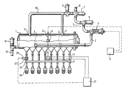
Fig. 1 schematically illustrates the apparatus according to the present
invention from the side and partly in section;
S Fig. 2 shows, on a larger scale, a part of the apparatus as shown in
Fig. 1, partly in section; and
Fig. 3 is a section taken through a reducer according to Fig. 2.
DESCRIPTION OF PREFERRED EMBODIMENT
That version of the apparatus according to the present invention
which is shown on the Drawings is intended for simultaneous filling of eight
packaging containers or bottles which, by means of conveyor devices (not
shown), are placed in filling position beneath the apparatus. The apparatus
may be integrated in a larger packing machine, but it is also possible to
employ the apparatus according to the present invention for filling
packaging containers which are advanced stepwise on a conveyor. The
practical design of the apparatus may, of course, be modified within broad
limits as long as the fundamental construction of the apparatus remains
unchanged and falls within the spirit and scope of the appended Claims.
The apparatus according to the present invention for simultaneous
filling of a plurality of packaging containers comprises an elongate holding
tank 1 which has convex end walls and is designed as a pressure tank so
as to withstand a certain inner excess pressure. The volume of the tank
should be at least twice the total volume of those packaging containers
which are filled simultaneously. A larger tank volume is to be preferred,
since the level on intermittent tapping of contents with then vary to a lesser
degree than would be the case if a small tank is employed. At one end wall
of the holding tank 1, there extends an inlet pipe 2 disposed axially along
the bottom of the tank and displaying two outlet holes 3 spaced along the
length of the tank. The opposing end of the inlet pipe 2 is in communication
with a flow 'regulator 4 in the form of a pump or a valve which, via a further
pipe 5, a washing valve 6 and an inlet valve 7, is cannected with an intake 8
for the Intended contents. The intake 8 may be connected to a main
reservoir (not shown) or to some other type of source for the intended
contents.
~~ 1~~~~
4
Using the inlet valve 7 the intake 8 can, when the system is washed,
be connected via a further washing valve 9, to a washing conduit which
discharges at two spaced-apart points in the upper region of the holding
tank 1 where the washing conduit 10 is connected to two so-called sprinkler
roses 11, i.e. ball-shaped outlet nozzles which are perforated on their
surface and are of the type which is normally employed for spreading
washing and cleaning liquid for the cleaning of tanks (C!P processes).
Centrally in the holding tank 1, there is also disposed a level meter
12 which, for example, can operate together with a float 13 whose position
is transmitted electrically to an exteriorly disposed level regulator 14 of
the
known type which is employed to control a valve or pump in response to a
signal, i.e. in the present case the flow regulator 4. Naturally, other types
of
level meters 12 may also be employed, for example level probes or different
types of signal transmitters and signal receivers.
The holding tank 1 also displays a drainage conduit 15 discharging
from the lower region of the tank and closable by means of a bottom valve
16.
At the lower region of the holding tank 1, there is provided a number
of aligned outlets to flow paths 17 which extend substantially vertically
downwards to filler valves 18 disposed at the lower ends of the flow paths.
The housing of each filler valve contains a vertically displaceable valve
body 19, a valve seat 20 disposed at the lower end of the valve body, and a
substantially vertically upwardly extending spindle 21 carrying the valve
body. The spindle 21 or its extension is, via sealing members 22 at the
upper end of the filler valve, in communication with a linkage 23 whose
upper end is in turn pivotally connected to a transfer beam 24. The transfer
beam extends horizontally over all valves 18 and is, via corresponding
linkages 23, connected to each one of the valves so as to make for
concerted operation by vertical displacement of the beam 24. The beam 24,
3J which is journalled in a known manner (not shown on the Drawings) for
permitting operation, is actuated by a prime mover 25 in the form of a piston
and cylinder unit which is connected to the beam 24 for displacing the
beam between a lower position in which all valve bodies 19 abut against
their valve seat 20 so that the filler valves 18 are closed, and an upper
position in which the valve bodies 19 are spaced from their respective valve
seat 20 so that contents may freely flow from the holding tank 1, via the flow
2~~~~~~
paths 17 and out through each respective filler valve 18 to packaging
containers (not shown) disposed beneath the valves.
In order to permit controlling of the filler valves 18 so that a suitable,
uniform metering of contents can be ensured, there is disposed, in one of
5 the flow paths 17', a flow meter 26 which is of conventional type and
electrically meters the volume of liquid passing in the flow path 1T. The flow
meter 26 is electrically connected to a control device 27 which may be of
the known type which is employed for operating, for instance, a piston and
cylinder unit of the type which constitutes the prime mover 25.
Each one of the flow paths 17 further includes a reducer 28 which is
mounted in the flow path between the holding tank 1 and the filler valve 18.
In the flow path 1 T fitted with the flow meter 26, the reducer 28 is mounted
downstream of the flow meter 26 seen in the direction of flow of the
contents.
The reducer 28, which is shown on a larger scale in Fig. 3, is in the
form of a washer or throttle with a channel 29 of an area which is reduced in
relation to the area of the flow path 17, with the result that the through
flow
area of the reducer 28 is less than 50% of the average area of the flow path
17. Upstream of the channel 29, seen in the direction of flow of the contents,
the reducer 28 presents an inlet cone 30 which forms a transition between
the larger flow area in the flow path 17 and the reduced area of the channel
29. The reducer 28 is also provided with an outlet cone 31 located
downstream of the channel 29 and forming a transition to the larger flow
area in the section of the flow path 17 located after the reducer 28. The
inlet
cone 30 displays an entry angle of between 5 and 20°, while the outlet
cone
31 has an angle of flare of between 60 and 180°. Naturally, these
values
are adapted to that type of contents which is to be filled, as well as the
quantity of contents to be batched every time the filler valves 18 are
opened. On filling of freely flowing contents, for example milk, into one
litre
packages, it has proved appropriate to employ an inlet cone 30 which has a
top or entry angle of approx. 10°, while the outlet cone 31 should,
given
similar conditions, display a flare angle of approx. 90°.
As a result of the presence of the reducer 28 - which is of decisive
importance to the flow resistance in the flow paths 17 - it will be possible
to
balance all flow paths so that a substantially completely uniform flow
resistance occurs, which ensures a uniform filling despite the fact that only
a
6
single flow path 1T is provided with a flowmeter 26 and is operative, via the
control device 27, simultaneously to control all filler valves 18 in a uniform
manner. Possible imbalances in the flow resistance depending upon the
differing placement of the flow paths in relation to the centre of the holding
tank, inaccuracies in the design of the flow paths and their inner surtaces,
the presence of a flowmeter 26 in but a single one of the flow paths, as well
as other conceivable factors of influence can be completely cancelled out
by individual design of the different reducers 28. When these have thus
been given such design that a uniform flow is obtained in all flow paths,
control of the content volume can be guaranteed with a satisfactory degree
of accuracy (approx. t 2% volume accuracy) for a very long period of
running time.
When the apparatus according to the present invention is reduced
into practice, contents are fed via the intake 8, the washing valve 9 being
closed so that the contents reach the flow regulator 4 via the pipe 5 and the
open washing valve 6. Depending upon the position of the regulator 4, the
contents are permitted to flow via both outlet holes 3 of the inlet pipe 2,
into
the holding tank, where the surface of the liquid lifts the float 13 until the
level meter 12 emits, via the level regulator 14, a signal to the flow
regulator
4 to discontinue or throttle the inflow of contents in the holding tank 1.
When the conveyor (not shown) has placed eight upwardly open,
preformed packaging containers beneath the filler valves 18, the control
device 27 receives a signal so that the prime mover 25 is actuated to raise
the beam 24 to its upper position, in which event the linkages 23 actuate the
valve bodies 19 to the upper, open position. Hereby, contents may flow via
the flow paths 17 and filler valves 18 so that filling of the packaging
containers is commenced. When the flowmeter 26 has registered that the
desired volume of contents has passed in the flow path 1T, a signal is once
again emitted to the control device 27 to close the filler valves 18, all
packaging containers having, thanks to the symmetric flow in the different
flow paths 17, received the predetermined volume of contents with a high
degree of precision. The outflow of contents via the flow paths 17 affects the
level in the holding tank 1 which is registered by the level meter 12 so that
the slow regulator 4 is ordered to permit intake of the volume shortfall of
contents into the holding tank. It will hereby be ensured that the liquid
pressure in the different flow paths 17 is always kept within certain limits,
at
~~c~l~~~~~
7
the same time as a sufficient quantity of contents for subsequent filling
cycles is always available in the holding tank. Of course, the holding tank 1
also includes an air bleeder aperture (not shown) so that its inner volume is
in contact with the ambient atmosphere via a suitable filter, but it is also
possible to pressurize, via the bleeder aperture, the holding tank so as to
permit an increase of the flow rate in the flow paths 17 when the filler
valves
18 open. Similarly, a slight excess pressure in the holding tank 1 may be
employed when contents of a higher viscosity are to be filled, e.g. juice or
cordial of a thicker consistency. Hereby, the apparatus according to the
present invention can be employed not only for freely flowing, water-like
contents, but also for a large number of the most commonly occurring
packed drinks.
In practice, the apparatus according to the present invention has
proved to function well and entail considerable cost savings, since a large
number of flow paths can be controlled from a single flowmeter, instead of
the necessity, as previously, of utilizing the same number of flowmeters as
the number of flow paths, or alternatively a corresponding number of active
dispensing devices such as piston pumps or the like. This simplification
implies not only a considerable cost saving in connection with design,
construction and manufacture of the apparatus, but also entails that after-
sales service and monitoring are simplified and made more economical,
since the apparatus contains very few moving or adjustable parts.
The present invention should not be considered as restricted to that
described above and shown on the Drawings, many modifications being
conceivable without departing from the spirit and scope of the appended
Claims.