Note: Descriptions are shown in the official language in which they were submitted.
213~7~3
Attorney Docket No.: IPM-114-CIP
IMPROVEMBNT8 IN VIBRATOR8
This invention relates generally to improvements in
vibrators used for all the purposes for which vibrators are
currently employed including compacting densifying, feeding,
conveying and homogenizing. More particularly, this invention
relates to an annularly configured vibrator that transmits
vibrations radially outward through an outer core and includes a
passageway through the axial center of the vibrator. The
configuration of the vibrator enables the vibrator to be disposed
within a large piece of equipment and further enables other
functional elements of the equipment such as drive shafts,
conduits or cables to be passed through the vibrator.
BACRGROUND OF TRE lNv~..lON
Industrial vibrators have a wide variety of uses. Vibrators
have been used in hoppers, bins and railcars to keep granular
materials flowing as they should. Vibrators have also been used
in connection with structural and architectural concrete because
vibration of wet concrete helps consolidate the concrete for a
stronger, more durable structure.
Although pneumatic vibrators came in a variety of
embodiments the general type of vibrators to which the present
invention is concerned supply air pressure through an inner,
substantially cylindrical and solid shaft. Air passes through
passageways in the shaft and engages a vane which directs the air
substantially in one circumferential direction. The air, now
proceeding in a substantially circular direction, engages an
213073 3
inner roller thereby causing the inner roller to rotate. The
inner roller rotates in an eccentric orbit due to the presence of
the vane which is disposed between the inner roller and the
vibrator shaft. The inner roller is disposed within an outer
roller and the rotating inner roller engages the outer roller
thereby causing the outer roller to rotate eccentrically about
the inner roller and shaft. The eccentric rotation of the inner
and outer rollers about the shaft and within the vibrator body
transmits vibrations radially outward through the outer roller
and any structure associated therewith.
The primary drawback to this otherwise efficient design is
the general configuration of the vibrator. The vibrator is
cylindrical disc shaped in configuration which limits use of the
vibrator in multi-component equipment. For example, during the
construction of concrete pipe or concrete cylinders, it is highly
desirable to apply vibration to the prepacked concrete. Further,
it is highly preferable to vibrate the concrete immediately after
it is packed with either a longbottom cylinder, a packerhead or a
combination of the two. To vibrate the concrete immediately
after it is packed, the vibrator should be disposed immediately
below the packerhead. However, this configuration is not
possible with many current disc shaped vibrator designs because
the drive shaft for the packerhead or longbottom must be disposed
2S below the packerhead or longbottom. Therefore, a cylindrical
vibrator must be disposed below the drive shaft and drive
mechanism of the packerhead or longbottom and, hence,
-- 2
213i)~33
substantially below the longbottom or packerhead. By contrast,
an annularly configured vibrator could be disposed immediately
below the packerhead because the drive shafting of a counter
rotating packerhead assembly could be passed through the center
of the vibrator thereby enabling the vibrator to be disposed in
close proximity to the packerhead. Further, the drive shafting
of a longbottom assembly could also be passed through the
vibrator enabling the longbottom assembly to be disposed
immediately above or below the vibrator, depending upon the
design of the pipe making machinery.
Other applications of an annularly configured vibrator will
be apparent to those skilled in the art. An annularly configured
vibrator will have applications in the design of multi-component
equipment or systems where the vibrator is but one component that
must be disposed between or adjacent to other functional
components. The primary benefit of such vibrators when used with
other functional elements or parts of machinery or equipment is
that the driving mechanism for the system can pass through the
vibrator thereby providing greater flexibility to the designer of
the equipment.
8UMMARY OF TH~ l~.v~N.lON
The present invention provides an annularly configured
vibrator which includes an annular or ring-like top plate, an
annular or ring-like bottom plate, and a hollow outer cylindrical
vibrator body connected to the outer periphery of both the top
2~3~733
plate and the bottom plate. A hollow, cylindrical vibrator shaft
connects the inner periphery of the top plate to the inner
periphery of the bottom plate. The vibrator shaft also provides
fluid communication between a pressurized fluid supply and the
annular space bound by the top and bottom plates and the body and
shaft.
The annular space includes three primary components: a
vane, an inner roller and an outer roller. Pressurized fluid
enters the annular space through slots or ports disposed in the
shaft and engages the vane which directs the pressurized fluid
primarily in one circumferential direction. The vane also
oscillates inward and outward and maintains contact with the
inner surface of the inner roller. In the case of pressurized
air, the air then engages the inner surface of the inner roller
thereby causing the inner roller to rotate. The inner roller
does not rotate in a circular orbit due to the engagement with
the vane and the inward/outward oscillation of the vane and
therefore the inner roller rotates eccentrically about the
outside surface of the vibrator shaft. The outer roller is also
cylindrical in configuration and begins to rotate upon engagement
with the inner roller. The eccentric rotation of both the inner
roller and the outer roller about the vibrator shaft imparts
vibration outward through the vibrator body.
213~733
Pressurized fluid or pressurized air exits the annular space
through slots disposed preferably in the bottom plate but the
slots may also be disposed in the top plate or vibrator body.
In the preferred embodiment, the vane is fabricated from
resilient yet pliable material whereby the vane maintains contact
with the inside surface of the inner roller. The vane is held in
place within a slot disposed in the vibrator shaft. Apertures
extending from an air channel in the shaft communicate with the
slot to provide fluid communication from the pressurized fluid
supply through the slot and against the vane. The vane then will
oscillate radially outward and direct the air flow in primarily
one circumferential direction which initiates rotation of the
inner roller. The engagement between the outer surface of the
inner roller and the inner surface of the outer roller initiates
rotation of the outer roller.
It is therefore an object of the present invention to
provide an annularly configured vibrator having a central passage
of a size sufficient to receive other operating and functional
elements of the system in which the vibrator is incorporated,
including central shafting.
Yet another object of the present invention is to provide an
improved pneumatic vibrator as above described.
2130733
DETAILED DESCRIPTION OF THE DRAWING8
This invention is illustrated more or less diagrammatically
in the accompanying drawings, wherein:
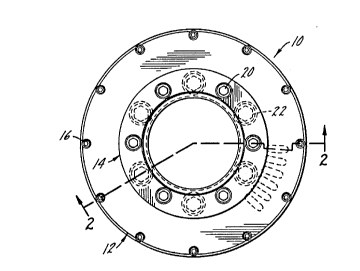
Figure 1 is a top plan view of a vibrator made in accordance
with the present invention, particularly illustrating a plan view
of the top plate;
Figure 2 is a section view taken substantially along line
2-2 of Figure l;
Figure 3 is a side plan view of the vane shown in Figure 2
but vertically rotated 180~ from its Figure 2 position;
Figure 4 is a end view of the vane shown in Figure 3;
Figure 5 is a bottom plan view of the vibrator shown in
Figure 2 particularly illustrating the bottom plate thereof;
Figure 6 is a partial section view taken substantially along
line 6-6 of Figure 5;
Figure 7 is an elevation view of the vibrator shaft shown in
Figure 2;
Figure 8 is an end view of the vibrator shaft shown in
Figure 7;
2l3a733
Figure 9 is a section view taken substantially along line
9-9 of Figure 8;
Figure 10 is a top plan view of the bearing used in
connecting the top plate to the vibrator shaft shown in Figure 2;
Figure 11 is a section view taken substantially along line
11-11 of Figure 10;
Figure 12 is a bottom plan view of the top plate shown in
Figure 1;
Figure 13 is a section view taken substantially along line
13-13 of Figure 12;
Figure 14 is a bottom plan view of the bottom plate shown in
Figure 2;
Figure 15 is a section view taken substantially along line
15-15 of Figure 14;
Figure 16 is a top plan view of the vibrator body shown in
Figure 2;
Figure 17 is a section view taken substantially along line
17-17 of Figure 16;
213~733
Figure 18 is a plan view of the inner roller shown in
Figure 2;
Figure 19 is a section view taken substantially along line
19-19 of Figure 18;
Figure 20 is a plan view of the outer roller shown in
Figure 2;
Figure 21 is a section view taken substantially along line
21-21 of Figure 20;
Figure 22 is a top plan view of a second embodiment of a
vibrator made in accordance with the present invention;
Figure 23 is a section view taken substantially along line
23-23 of Figure 22;
Figure 24 is a side view of the vane illustrated in
Figure 23 but vertically rotated 180~ from its Figure 23
posltlon;
Figure 25 is an end view of the vane shown in Figure 24;
Figure 26 is a bottom plan view of the vibrator shown in
Figure 23;
213û733
Figure 27 is an elevation view of the vibrator shaft shown
in Figure 23;
Figure 28 is an end view of the vibrator shaft shown in
Figure 27;
Figure 29 is a section view taken substantially along line
29-29 of Figure 28;
Figure 30 is a bottom plan view of the top plate shown in
Figure 22;
Figure 31 is a section view taken substantially along line
31-31 of Figure 30;
Figure 32 is a top plan view of the bottom plate shown in
Figure 23;
Figure 33 is a section view taken substantially along line
33-33 of Figure 32;
Figure 34 is a vertical section view of the vibrator body
shown in Figure 23;
Figure 35 is an end view of the inner roller shown in
Figure 23;
2130733
Figure 36 is a section view taken substantially along line
36-36 of Figure 35;
Figure 37 is an end view of the outer roller shown in
Figure 23;
Figure 38 is a section view taken substantially along line
38-38 of Figure 37;
Figures 39A through 39D illustrate the eccentrical orbit of
the inner and outer rollers of the vibrators illustrated in
Figures 2 and 23; and
Figures 40A through 40D illustrate the eccentrical orbit of
an inner and outer roller of an alternative embodiment of the
vibrator of the present invention.
It should be understood that the drawings are not
necessarily to scale and that the embodiments are sometimes
illustrated by graphic symbols, phantom lines, diagrammatic
representations and fragmentary views. In certain instances,
details which are necessary for an understanding of the present
invention or which render other details difficult to perceive may
have been omitted. It should be understood, of course, that the
invention is not necessarily limited to the particular
embodiments illustrated herein.
-- 10 --
~130733
DETAILED DESCRIPTION OF THE DRAWINGS
Like reference numerals will be used to refer to like or
similar parts from Figure to Figure in the following description
of the drawings.
~5
Two embodiments of the present invention are illustrated in
the drawings, specifically at Figures 1 through 21 and at
Figures 22 through 38.
Turning first to Figure 1, a top plan view of a vibrator 10
is illustrated, particularly illustrating the top plate,
indicated generally at 12, and the bearing, indicated generally
at 14. Referring collectively to Figures 1 and 2, the cap screws
indicated at 16 are used to affix the top plate 12 to the
vibrator body indicated generally at 18. The cap screws 20 are
used to attach the bearing 14 to the top plate 12 and then the
cap screws shown at 22 are used to attach the top plate 12 and
bearing 14 to the vibrator shaft indicated generally at 24.
Still referring to Figure 2, the bottom plate indicated
generally at 26 is attached to the vibrator shaft 24 with the cap
screws 28. The bottom plate 26 is then attached to the ring 30
with the cap screws indicated at 32. The ring 30 is attached to
the inside surface 34 of the vibrator body 18.
Still referring to Figure 2, the vibrator shaft 24 provides
fluid communication between the port 36 which is in communication
~13~733
with the pressurized fluid supply (or pressurized air supply) and
the annular space defined by the top plate 12, bottom plate 26,
shaft 24 and body 18. Air enters the port 36 and proceeds up
through the conduit or channel 38 in shaft 24. A plurality of
apertures 40 spaced along the channel 38 direct the air flow
against the vane indicated generally at 42 which reciprocates in
slot 54, see Figure 8. As will be discussed below, the vane 42
directs the air flow against the inner roller, indicated
generally at 44, thereby causing it to rotate and engage the
outer roller, indicated generally at 46, causing it to rotate.
The eccentric rotation of the inner roller 44 and outer roller 46
about the vane 42 and shaft 24 results in vibrational energy
being transmitted outward through the vibrator body 18.
Turning to Figure 3, the vane 42 features a plurality of
slots indicated generally at 48. Air proceeds through the
apertures 40 (see Figure 2) and engages the slots before it is
directed outward generally in the direction of the arrow 50 (see
Figure 4) where it engages the inside surface 52 (see also
Figure 19) of the inner roller 44. The placement of the slots 48
along the vane 42 as shown in Figure 3 reflects the variances in
the air pressure along the height of the conduit 38 (see
Figure 2). Specifically, as air enters through the port 36 and
proceeds up through the conduit 38, the air pressure along the
conduit 38 will vary. The spacing of the slots 48 along the vane
42 and the spacing of the apertures 40 along the conduit 38
reflect the variances in pressure along the height of the conduit
- 12 -
213~7~3
38 and are spaced to distribute the air pressure evenly against
the inside surface 52 of the roller 44 to efficiently begin the
rotation of the roller 44. The vane is received in the slot 54
disposed in the shaft 24 (see Figure 7). Air is released from
the annular space that contains the rolIers 44, 46 through the
slots in the bottom plate 26 indicated at 56 (see Figures 2, 5
and 14).
Turning to Figure 5, the bottom plate 26 is attached to the
ring 30 via the cap screws 32 and the ring 30 is welded or
otherwise attached to the inside surface 34 of the vibrator body
18. As noted above, the slots indicated generally at 56 release
the air or pressurized fluid from the vibrator 10. The bottom
plate 26 may also accommodate a proximity switch indicated
generally at 58 which may shut the vibrator off in the event an
object engages the undersurface 60 of the ring 30 or, as shown in
Figure 6, if an object engages the probe 62 which extends
downward from the proximity switch 58 through the ring 30.
Turning now to Figures 7 through 9 collectively, the
vibrator shaft 24 includes the beveled extensions 64, 66 that are
received in the top plate 12 and bottom plate 26 respectively.
The slot 54 receives the vane 42 and the apertures indicated at
40 direct pressurized fluid at the slots 48 of the vane 42 (see
Figure 3). The threaded holes 68 receive the cap screws 22 which
attach the top plate 12 to the shaft 24. The holes 70 receive
- 13 -
213~733
the cap screws 28 which attach the bottom plate 26 to the shaft
24.
The bearing 14 is illustrated in Figures 10 and 11. The
holes 71 receive the cap screws 20 (see Figures 1 and 2) which
attach the bearing 14 to the top plate 12. The slot 72 receives
the head and washer of the cap screws 22 (see also Figures 1 and
2) which attach the top plate 12 to the vibrator shaft 24.
lo Turning to Figures 12 and 13, the holes 74 of the top plate
12 receive the cap screws 16 that attach the top plate 12 to the
upper end of the vibrator body 18. The holes 76 receive the cap
screws 22 that attach the top plate 12 to the vibrator shaft 24.
The holes indicated at 78 receive the cap screws 20 that attach
the bearing 14 to the top plate 12. The top plate 12 also
includes plurality of slots or channels 80 that increase the
turbulence of the air or fluid flow in the annular space defined
by the shaft 24, top plate 12, bottom plate 26 and body 18. As
seen in Figure 13, the slots 80 do not pass through the top plate
12. In contrast, the slots 56 disposed in the bottom plate 26
(see Figure 14) pass through the bottom plate 26 and not only
increase the turbulence of the air flow in the annual space but
also act to release air or fluid pressure from the vibrator 10.
Returning to Figure 13, the beveled upper end 64 of the
shaft 24 is accommodated in the recess 81 of the top plate.
Similarly, the beveled lower end 66 of the shaft 24 is
- 14 -
2~3~733
-
accommodated in the recess 82 disposed in the bottom plate as
shown in Figure 15. Referring to Figures 14 and 15, the bottom
plate includes a plurality of holes 84 to accommodate the cap
screws 32 which attach the bottom plate to the ring 30 (see
Figure 2). The bottom plate also includes the plurality of holes
indicated generally at 86 that accommodate the cap screws 28
which attach the bottom plate 26 to the vibrator shaft 24.
The vibrator body is illustrated in Figures 16 and 17. The
ring 30 is welded or otherwise fixedly attached to the inside
surface 34 of the vibrator body 18. Accordingly, the vibrator
bottom plate is inserted down through the upper end 88 of the
vibrator body 18 before it is accommodated in the recess 90. The
holes indicated at 92 accommodate the cap screws 16 as shown in
Figure 2. The holes indicated at 94 accommodate the cap screws
32 which fixedly attach the bottom plate 26 to the ring 30. The
recess 96 disposed in the ring 30 is in alignment with the
air-release apertures or slots 56 disposed in the bottom plate
26. The hole 98 disposed in the ring 30 accommodates a
downwardly extending probe 62 of a proximity sensor 58 (see
Figure 6).
The inner roller 44 and outer roller 46 are illustrated in
Figures 18 through 21. As seen in Figures 18 and 20, the inner
roller 44 is thinner and less bulky than the outer roller 46.
Accordingly, in operation, air or pressurized fluid engages the
inside surface 52 of the inner roller 44 and the inner roller 44
213û733
starts to rotate. Then, the outside surface 102 of the inner
roller engages the inside surface 104 of the outer roller 46.
Because the movement of the inner roller 44 is initiated by
pressurized air or fluid, it is preferable to employ a relatively
light inner roller 44 which, in turn, initiates the movement of
the heavier outer roller 46.
Turning now to Figures 39A through 39D, the rotation of the
rollers 44, 46 is illustrated. Referring first to Figure 39A,
the outside edge 103 of the vane 42 engages the inside surface 52
of the inner roller 44. Air engages the slots 48 in the vane 42
and is thereafter directed in the counterclockwise direction as
shown in Figure 39A. Turning to Figure 39B, the air pressure
coming off of vane 42 causes the inner roller 44 to rotate in the
counterclockwise direction as shown by the gap between the inner
surface 52 of the inner roller 44 and the outside surface of the
vibrator shaft shown at 100. As seen in Figures 39C and 39D, the
inner roller 44 continues to rotate about the outside surface 100
of the shaft 24 and the vane 42 oscillates from the fully
extended position as shown in Figure 39A to a collapsed position
as shown in Figure 39C. The engagement between the outside
surface 102 of the inner roller 44 and the inside surface 104 of
the outer roller 46 causes the outer roller 46 to rotate in the
counterclockwise direction. The engagement between the outer
edge 103 of the vane 42 and the inner surface 52 of the inner
roller 44 causes the inner roller 44 to rotate in an eccentric
fashion. In other words, the inner roller 44 does not rotate
213~73~
.
about a single axis due to the engagement between the inner
roller 44 and the oscillating vane 42. Consequently, the outer
roller 46 also rotates in an eccentric fashion. The irregular or
eccentric rotations of the inner roller 44 and outer roller 46
5 cause intense vibrations which are transmitted outward through
the vibrator body 18. A similar oscillation is illustrated with
respect to smaller rollers and an alternative embodiment in
Figures 4OA through 4OD.
Turning now to Figures 22 through 38, an alternative
embodiment is illustrated. The vibrator shown in Figures 22
through 39 is somewhat functionally similar to the vibrator 10
shown in Figures 1 through 21 and similar parts are identified
with the same reference number with the prefix "2" (i.e., the top
plate "212" as opposed to the top plate 12). In the embodiment
of Figures 22 through 38, the vibrator 210 is consistently
larger, and the bottom plate 226 is attached directly to the
vibrator body 218 as opposed to the ring 30 as shown in Figure 2.
Further, the vibrator body 218 is equipped with an outer ring 219
as shown in Figure 22 which is used to mount the vibrator 210
inside a core 221. The core 221 includes a ring 223. The core
221, in the example shown in Figure 23, may be used in the
fabrication of concrete pipe. The remaining functional elements
of the vibrator 210 are similar or analogous to the functional
elements described above with respect to the vibrator 10 shown in
Figures 1 through 21.
2~3~733
One of the primary benefits provided by the annular
configuration of the vibrators 10 and 210 is that functional
parts such as drive shafts, cables or conduits can be passed
through the vibrator which makes the vibrators 10 and 210 more
useful as one component of a multi-component system. In other
words, the designer of a multi-component system has greater
flexibility in the design of the system because an entire section
of the system need not be reserved for the pneumatic vibrator.
The vibrator can be spaced closely between two other components
and the functional elements such as drive shafts, conduits,
cables, etc. of adjacent components can be passed directly
through t-he vibrator.
Although only two embodiments of the present invention have
been illustrated and described, it will at once be apparent to
those skilled in the art that variations may be made within the
spirit and scope of the invention. Accordingly, it is intended
that the scope of the invention be limited solely by the scope of
the hereafter appended claims and not by any specific wording in
the foregoing description.
- 18 -