Note: Descriptions are shown in the official language in which they were submitted.
WO 93/16931 ~ ~ t~ U ~ ~ PCr/VS93/02032
Description
A~Paratus and Method ;
For Makinq A Reclosable Baq
Technical Field
This invention generally relates to packaging and
more specifically to a storage bag that is easily reclosed
and to the methods and apparatus for making such a storage
bag.
Backaround Art
There is a long-running effort to make a storage bag
that is easily opened and then reclosed. This effort has
led to cri~eria ~for judging the potential success of such
s~orage bags. Consumers require that such ~ags must be
easily opened, reclosed, and then reopened. The method
15 of reclosure must be positive. From a manufacturer's
standpoint, the method and apparatus required for forming
the bag and reclosure structure must be easily added to a
production line~, operate without any appreciable reduction
in~production rates,~add minimal production costs, have
20 the capacity to be used with bags requiring a freshness
- seal and produce little or no waste material. Generally
this prior effort has produced bags that either
incorporate a separate reclosable tie or an integral
structure that forms a tie.
The following patents are examples of bags with
separate reclosure ties:
3,311,288 (19~7~ ~emelson
3,426,959 (1969) Lemelson
3,6?4,135 (1972) Simon
,- 30~ 3,779,139 (1973) White
Each Lemelson patent discloses packages-with a tear
strip of plastic or metallic foil. The tear strip may
~ include a thr-ad, string, wire or ~eld for added strength.
-- ~ The~bag is reclosèd~by~separating the tie from the bag and
35 ~then~wrapping~and twisting;the tie around the bag.
The~Simon pat-nt discloses a roll of separable bags.
A line of perforations along an edge or top of each bag
, , .
SUBSTlrUTE SHEET
WO93/16~31 ~ ~;20 PCT/US93/02032
1 -2- ~
enables a section of the material to be removed for use as
a reclosure tie or tear strip. The tear strip may be
reinforced by one or more heat seals or by the application
of separate strengthening materials such as string,
5 deformable metal or another ply of film.
The White patent discloses a bag with a transverse
tear strip that can be removed from the end of the bag.
This tear strip then can be tied in an overhand knot to
reclose the bag.
Each of the foregoing reclosure tie structures
achieve some of the previously discussed criteria. Most
are relatively easy to use in reclosing a bag. Twisted
tie wraps are also relatively easy to remove in order to
reopen the bag. Those tied with overhand knots may or may
15 not be eaæy to open depending upon the ease with which the
oYerhand knot releases. However, these approaches have
not found great acceptance because they all incorporate
special structures or require very specialized apparatus
that can reduce production rates or increase materials and
20 manu acturing costs unacceptably. For example, the W~ite
patent discloses the formation of a bag with a series of
steps that is not readily adapted to continuous form and
fill processes as conventionally used in the food industry
and other industries. It requires special apparatus~ The
25 following patents disclose packaging that uses integral
tie strips that remain attached to a bag:
3,2l7,97l (1965~ Shvetz
l,l50,037 (1969) Plusplan (GB)
3,480,198 t1969) Repko
The Shvetæ patent discloses a bag that opens along a
transverse tear line that terminates inwardly of the edges
of the bag to form a tie. A longitudinal tear line allows
a portion of a reclosable tie to be separated into two
halves 8Uch that the reclosure tie or strip forms two
WO93/16931 ;~ PCT/US93/n2032
-3-
individual tie strips attached to opposite edges of the
bag. The two ties can be k~otted together. In another
version a side strip formed along an edge of the bag can
be partially separated to form a single tie strip.
The Plusplan patent discloses a similar structure in
which a marginal section of a ~ag separates from the main
portion of the bag along a tear line. However, the
reclosure tie does not completely separate from the bag.
The Repko patent discloses a similar structure in
lO which a~marginal portion, with a weld or heat seal for
strenqth, partly separates from a bag along a tear line
defined by a series of apertures. The tear termina~es at
an end point, so the marginal portion remains physically
attached to the bag.
Each of these structures either requires additional
materials or prevents the bag from opening fully when the
contents~are to be dispensed. Noreover, the ~epko patent
requires a sophisticated structure for forming the
plurality of apertures with seals intermediate and about
20 each aperture to maintain any freshness seal.
The following patents disclose the bags in which a
reclosure tie has an integral loop and tail section:
3,664,575 ~l972) Lake
4,549,657 (1985) Martin
25 4,609,107 (1~86) Martin et al
4,682,976 (~987) Martin et al
4,787,517 ~l988) Martin
In accordance with the Lake patent a p~rtion of a bag
, adjacent the top is formed with an intermediate seal that
30 extends partially across the bag to form a tail of a
- reclosure tie. Another transverse seal spaced from the
first seal ioins the layers of film to form a loop
- sectlon. This réolosure tie~can be separated from the bag
nd then cinches~the bag when the tail is wrapped around
:
-,
WO93/16931 PCT/US93/02032
,~t~ 4_
the bag and thread through the loop. However this
reclosure tie is disclosed in connection with storage bags
without freshness seals. That adaptation of this
structure to a bag with a freshness seal could increase
5 material costs unaccept~bly.
The Martin patents, U. S. Letters Patent Nos.
4,549,657 and 4,787,517, disclose a number of embodiments
of easily opened and reclosable bags. Oppositely disposed
sealing jaws form a closure seal with a reclosure tie and
l0 a freshness seal. The reclosure tie can be removed from
the bag without disturbing the freshness seal. The bag is
reclosed by wrapping the reclosure tie around the bag and
extending one end through a loop formed at the
intermediate section by the unsealed plies. In one
15 embodiment it is suggested that the reclosure tie be
formed as sealed plies of material except at an
intermediate section offset to one end of the tie, thereby
to form a tail.
In each of the Lake and Martin patents the loop
20 section incorporates a seal. ln many applications,
particularly those involving polyethylene-based film bags,
this seal is subject to failure. More particularly, as a
cinching force is applied by the tail portion, a large
portion of that force concentrates at an edge of the seal
25 in the loop section. The seal then can begin to fail due
to delamination of the plies and tearing of the material.
When this occurs, the integrity of the loop section is
lost and the reclosure tie no longer is functional. The
! Martin et al patents, U. S. Letters Patent Nos. 4,609,107
30 and 4,682,976, disclose a reclosure tie formed as a tear
strip across a top of a polypropylene bag in a margin
portion beyond a freshness seal. The tear strip has a
mold formed transversely in the bag for strength; ît tears
along a series of specially formed slots or perforations
WO93/16~31 ~ U PCT/US93/02032
through the material in the margin portion beyond th~
freshness seal. In one embodiment a portion of the bag
omits the mold proximate an edge thereby to provide a
reclosure tie with a short mold channel and a loop spaced
5 from one end. It is suggested that the other end of the
reclosure tie pass through the loop as a tail to cinch the
bag. Cinching, in this case, is also dependent upon an
interaction of nubs formed on the edges of the reclosure
tie. This approach is disclosed in connection with heat
lO sealable, treated ceIlophane or other thin organic polymer
materials. In fact, the bag has been used with
polypropylene bags, but is not readily adapted for
- polyethylene-based~bags. First, it is difficult to form a
mold and channel in such material. Second-, the cinching
15 forces still act against a s~al thereby incorporating a
potential failure point.
.
Disclosure of Invention
T~erefore it is an object of this invention to
provide a method and apparatus for manufacturing a
20 reclosable bag that is easy to open and contains a
reclosure tie that facilitates the subsequent closure and
reopening of the bag.
It is another object of this invention to provide a
method and apparatus for manufacturing a reclosable bag
25 with an integral reclosure tie that does not require the
addition of discrete elements or special components.
Another object of this invention is to provide a
method and apparatus for manufacturing a reclosable bag
with an integral reclosure tie that can be manufactured
30 without the generation of waste materials.
Still another object of this invention is to provide
~;~ a metbod and~apparatus for manufaaturing a reclosable bag
and~reclosing tie structure in which additional
, , ~
WO93/16931 PCT/US93/02032
~ 6-
manufacturing costs are limited primarily to the cost of ;~
additional material.
Still another object of this invention is to provide
a method and apparatus for manufacturing a reclosure tie
for a reclosable bag in the form of an integral reclosure
~ie with a strong integral loop portion and a tail
portion.
In summary and in accordance with one aspect of this
invention a storage bag with a reclosure tie is produced
10 by forming a sealable, elastic, polymeric film into an
open-ended, hollow structure formed by walls of the film
~nd extending along a first axis. A portion of the hollow
structure is clamped along a second axis that is
transverse to the first axis to form a margin portion in
15 coextensive film wall portions. The margin portion has
first and seeond sections disposed along the second axis
to provide a boundary between successive storage bags. A
line of perforations is formed in the margin portion that
is parallel to the second axis. The film walls are also
20 severed in the margin portion along a severance line that
is parallel to in space from the second axis. The
perforation and severanc line define a removable closure
- tie between the perforation and severance lines and an
àdjacent first sealing area. A first seal is formed in
25 the film walls along a line in the first sealing area that
is parallel to khe second axis and is coextensive with
both the f irst and second sections. A second seal is
formed in the removable closure that is para1lel to the
second axis and extends only across the first section
30 whereby the film walls in the second section remain
unsealed. The unsealed film walls are free of any film
structure that fails by delamination.
In accordance with another aspect of this in~ention,
apparatus for~s storage bags from a continuous cylinder
WO93/16s31 i ~ PCT/US93/02032
-7-
lying along a first axis and formed of a sealable elastic
polymeric film. Each bag includes a contents pouch and an
integrally formed reclosure tie for reclosing the bag.
This apparatus includes a clamping structure for clamping
5 a portion of the continuous cylinder along a second axis
that is transverse to the first axis to form a margin
portion in coextensive film wall portions of the
continuous cylinder. The margin portion has first and
second sections disposed along the second axis for
10 providing a boundary between successive storage bags. A
perforating structure perforates the film walls in the
~argin portion along a perforation line that is parallel
to the second axis. A severing structure severs the film
walls in the margin portion along a severance line that is
15 parallel to and spaced from the second axis there~by to
form a removable closure tie in between the perforation
ana~severance lines and an adjacent first sealing area. A
first sealing structure forms a first seal between the
film walls along a line in the first sealing area that is
20 parallel to the second axis and that is coextensiYe with
the first and second sections. A second sealing structure
forms a second seal along a line in the removable closure
tie that is parallel to the second axis and that extends
only across the first end to form a tail in the remo~able
25 reclosure tie. The film walls in the second section
remain unsealed to form a loop that remotely to the tail
is free of any film structure that fails by delamination.
Brief Descri~tion of Drawi~s
,. , i
The appended claims particularly point out and
30 distinctly claim the subject matter of this invention.
The various objects, advantages and novel features of this
invention will be more fully apparent from a reading of
the ~following detailed description in conjunction with the
~'
, ~ .
W O 93/16931 PC~rtUS~3/02032
accompanying drawings in which like reference numerals
refer to like parts, and in which: ~
Fig. 1 is a perspective view of one embodiment of a
storage bag constructed in accordance with this invention;
Fig. 2 is a perspective view of the storage bag shown
in Fig. 1 with a reclosure tie removed;
Fig. 3 is a view of the storage bag shown in Fig. 1
with the reclosure tie used for resealing the bag;
Fig. 4 is a perspective, in schematic form, of
10 assembly equipment used for filing bags such as the
storage bag in Fig. 1;
- Fig. 5 is an side view of front and rear sealing jaws ;
of Fig. 4 in a separated position; ~:
Fig. ~ depicts the sealing jaws in Fig. 5 moved to an
15 operating position;
Fig. 7 is a perspective of a portion of a rear
sealing jaw;
Fig. 8 is a top view of a portion of a front sealing
jaw useful in accordance with the equipment shown in Fig.
20 4;
Fig. 9 is a side Yiew of the front sealing jaw shown
in Fig. 8;
Fig. 10 is a view of a cutting blade used in the
front sealing jaw of Fig. 7;
Fig. 11 is a view of a perforation blade used in the
front sealing jaw of Fig. 7;
Fig. 12 is a perspective view partially in exploded
foxm that discloses an end portion of the rear sealing jaw
shown in Fig. 5;
Fig. 13 is a perspective view of an alternative
embodim~nt o~ a storage bag shown in Figs. 1 through 3;
Fig~ 14 is another embodiment of a storage bag that
utilize~ this invent.ion;
WO93/16931 ~ V PCT/US93/02032
_g_
Fig. 15 is a perspective view of still another
embodiment of a storage bag that utilizes this invention;
Fig. 16 is a perspective, in schematic form of a
sealing jaw that utilizes resistance heating;
Fig. 17 is an exploded view of a portion of the
sealing jaw shown in Fig. 16;
Fig.18 is a cross-sectional view of front and rear
sealing jaws in an open state and taken along lines 18-18
in Fig. 16.
Fig. l9 is a cross-sectional view of the sealing jaws
- as shown in Fig. 18 in a closed position and taken
along lines 18-18 in~Fig. 16; and
Fig. 20 is a cross-sectional view of the sealing ~s
shown in Fig. 19/ but taken aIong lines 20-20 in Fig. ~.
15 Best Mode for CarrYina Out the Invention
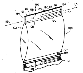
Fig. 1 o~ the drawings depicts a storage bag
indicated generally at 100. Typically the bag 100 wiIl be
- formed of an elastic coextruded polymer such as high
-~ density polyéthylene and ethyl vinyl acetate or a
20 c~polymer including polyethylene. When heat is applied to
adjacent film layers, the~ material seals, typically by
~fusing. These films are also characterized by reasonably
high~ resistance to puncture and to the initiation of a
tear. It is intended that the phrase "sealable elastic
25 polymeric material" include al~ such polyethylene-based
materials ~s well as ~ther~materials that e~hibit similar
characteristic~. Such materials may al50 be co-extruded
, with other films for particular applications and still use
the foregoing characteristics.
~; 30 Fig. 1 also depicts an adjacent, or lower, bag 101
;~ ~ after as being severed from the bag 100 as occurs in a
normal production o~ successive storage bags. Each bag
has~the same basic construction. Using the storage bag
;"~
WO93/16931 PCT/US93/02032
--10-- , :
100 as an example, the film forms a generally cylindrical
open-ended pouch 102 comprising a sheet of a sealable
elastic polymeric film wrapped around a cylinder. The
edges overlap and produce a longitudinally extending back
5 seam 103. A "bottom" seal 104 and a "top" seal 105 close
the ends of the pouch 102 so the bag can store food or
other articles. A perforation line 106 defines a boundary
between the storaqe bag 100 and an attached, integral
réclosable tie 110.
Specifically the reclosable tie 110 constitutes a
margin portion and includes film layers on extensions 111 `
and 112~ beyond the~seal 105. The~extensions 111 and 112
ter inate at margin~end portions 113 and 114 and the
reclosure tie 110 lies along an axis 115 that parallels
15 the~top seal 105. Two fused seals 116 and 117 parallel
the~axis 1~15 and~-xtend from the margin end 113 to a
position~inter ediate~the back seam 103 and the margin end
114~and~spaced from the margin end 114. A top edge 118 of
the-extensions lll and 112 constitutes a parting line for
20~ adjàcent bag. ~Reference numeral 118 also designates the
parting line for the bags 100 and 101.
- The portion of the extensions 111 and 112 that are
; coextensive with the fused lines 116 and 117 along the
axis 115 produce a tail portion 120 in which the layers
25 111 and 112 are fused together. The remaining portions of
the extensions 111 and 112 including the end 114 form a
loop portion 121. As shown in Fig. 1, therefore, each of
a series of storage bags such as storage bags 100 and 101
~! i has an integral extension of the film forming two layers
30 beyond a top seal line. The extensions form a tail and
loop structure that ¢an be readily torn from the bag along
the perforation line 106.
To open the bag, a consumer tears the reclosable tie
;~fr#~the bag 100 along t~e perforation 106 as shown in
~" , ,~
,,,
WO 93/16931 ~ O PCr/US93/02032
Fig. 2. Then the consumer separates the film layers along
the top freshness seal 105 to open the bag fully. After
some of the contents are removed, the individual gathers
the bag 100 above the remaining contents to form a closed
5 neck 122 as shown in Fig. 3, wraps the reclosure tie 110
around the neck 122 and passes the tail portion 120
through the loop portion 121. When the consumer pulls the
tail portion 120, reclosure tie 110 slides longitudinally
such that the loop 121 adjacent the margin end 114 slides
10 along and tightens the noose formed around the gathered
neck 122.
All pressure on loop 121 is applied against the end
114 that is free of any material that might otherwise
delaminate, such as the back seam 103. When the loop 121
lS is~fiDly cinched in place and the tail portion 120 is
released,~ the material, that stretched in tension,
relàxes.~ The end margin 114 of the loop 121 cinches
against the tail portion 120 thereby preventing its
inadvertent loosening.~ However, as is characteristic in
20 such }oops, intentional release of the reclosure tie 110
is readily accompl`ished by sliding the end of the loop 121
toward the margin end 113 of the tail portion 120 thereby
releasing the cinching action and enabling a consumer to
readily remo~e the closure tie.
The bag 100 achieves all the above objects of this
invention. The reclosure tie 110 is formed integrally
with the bag during the bag forming and filling processing
and only with a nominal amount of additional material.
Thus, the cost of the bag 100 should not be significantly
30 greater than that of a conventional bag without the
-~ reclosure tie 110.
Moreover, comentional form, fill and æeal pouch
- ~ ~ - appar~tus~can produce ~ags,~ such as the bag 100 of Figs.
through ~3~, ~successi~ely w~ithout significant modification.
,, ,, ~ ~,
. ,. , . :
WO93/16931 ,J ~. ~ U ij ~J i] PCT/US93/02032
-12-
As shown in Fig. 4, such apparatus passes fusible, elastic
polymeric film 149 from a roll 150 past a guide roller 151
to a panning shoulder 152. The panning shoulder 152 forms
the film 149 into a folded, double thickness, vertically
5 moving web 153 about a cylindrical mandrel 154~ Heat
sealing apparatus 155 coacts with rollers 156 to insure
formation of the back seam 103. Thus the panning shoulder
152 and the mandrel 154 transform film in sheet form into
a continuously advancing open-ended cylindrical structure
10 153 that receives a measured amount of contents from a
hopper 157 dispensed through a cylindrical passage 160 in
the mandrel 15A. The contents then fall into a pouch that
has been formed above:the bottom seal 104 by front and
rear sealing jaws 161 and 162 that are shown only,in
15 diagrammatic form in Fig. 4.
More specifically, sealing jaws 161 and 162 initially
are brought together (in a horizontal plane in Fig. 4) to
grab the web material 153 from either side and then moved
along the axis of the mandrel (vertically in Fig. 4) to
20 pull the material 153 to a lower position. During thi,s
travel the.bags initially are perforated and cut along
lines 106 and 118. Then the sealing jaws form the upper
seal 105 in the bag 100 and the lower seal 104 in the next
~ag lOOA and the seals 116 and 117. The apparatus
25 simultaneously dispenses contents from the hopper 157 to
fill the bag lOOA.
When the jaws 161 and 162 reach the bottom of travel
along the mandrel axis they retract. At this point ths
lower bag, bag 100 in Fig. 4, drops away with its
30 contents. The jaws 161 and 162 then move baak along the
mandrel axis to a positi'on corresponding to the top of the
- filled bag. This is vertical motion shQwn by arrows 118
in Fig. 4. At the top of this motion the jaws again close
and grab the web 153 above the fill contents and begin a
WO93/16931 PCT/US93/02032
t3~
-13-
next cycle to pull another section of film intoappropriate position to form another ~ag.
With the exception of the sealing jaws 1~1 and 162,
Fig. 4 depicts conventional form and fill processing
5 equipment. In accordance with this invention, it is
merely necessary to substitute new sealing jaws 161 and
162 in this conventional apparatus to provide bags as
shown in Figs. 1 through 3. The controls and actuating
mechanisms that are involved with conventional heat
10 sealing jaws remain substantially unchanged.
SEALING JAWS
, One function for the front and rear sealing jaws 161
and 162 is gripping the material of the web 153 to pull
material down the mandrel for forming and filling a next
15 bag. Referring to Figs. 5 through 9, the front jaw 161
inc-ludes an upper gripper bar 163 that has a position
corresponding to an oppositely facing upper gripper bar
164 in the rear jaw 162. The front and rear sealing jaws
161 and 162 additionally have lower oppositely facing
20 gripper bars 165 and 166. When the sealing jaws 161 and
162 move from the retracted position shown in Fig. 5 to
the closed position shown in Fig. 6, they engage and grip,
- or clamp, the web material 153. As previously described,
web material between the upper and lower gripping bars
25 constitutes a margin portion between the bottom of the
upper bag and the ~op of the lower bag.
As the jaws 161 and 162 in the closed position shown
in Fig. 6 pull along the mandrel axis, that is downward in
! Fig. 6, two operations occur. First, a cutting blade 167
30 in the front sealing jaw 161 ad~ances through the web 153
into a recess 168 in the rear sealing jaw 162. This
produces the parting line 118 shown in Fig. 1.
Simultaneously a~perforation blade 169 moves from a
~; retracted position in the front sealing ~aw 161 through
,~
:: ,
', '
-
~ .. , ...... " . , .. .. .. ~,
WO93/16931 PCT~US93/02032
-14-
the web material and into a recess 170 in the rear sealing
jaw 162 thereby to form the perforation line 106 shown in
Fig. 1. A front sealing jaw body portion 171 carries the
blades 167 and 169 and recesses 168 and 170 in a
5 stationary water jacket 172 receive the blades 167 and
169.
The second operation occurs when an electrical
impulse passes through a set of parallel wires. More
specifically the body portion 171 carries an upper
10 pressure pad 173 tha~ presses the web material 153 against
a heating filament 174. A similar resilient pad 175
~resses a portion of the web material around a lower
heating filament 176. A single central pad 177 on the
body portion 171 presses the web material 153 against
15 parallel filaments 178 and 179. When these wires receive
an electrical impulse:, they produce sufficient heat to
fuse the film at the wires. The filament 174 produces the
bo~ttom seal 104 in Fig. 1. The filament 176 produces the
top seal 105 in Fig. 1. The filaments 178 and 179 produce
20 the sea}s 116 and 117 shown in Fig. 1 that extend
partially across the bag as described later~
SEAI,ING JAWS-GRIPPING STRUCTURE
-The structure of the rear jaw gripper bars can be
seen by referring to Fig. 7. Both the upper and lower
2S gripper bars 164 and 166 have tha same basic structure
therefore only the gripper bar 164 is described in detail.
A frame member 180 supports the sealing jaw 162 and a
mounting plate 181 attaches by bolting or other
i conventional means to the frame memb~r 180. The mounting
30 plate 181 extends across the width of the frame. An upper
gripper plate 182 bolts or otherwise attaches across the
face of the mounting plate 18~ to form a secure L-shaped
mounting bracket for the upper gripper 164. The resulting
rigid structure provides a front surface for the gripper
; .
',~:'
:, ~
WO93/16931 } ~ PCT/US93/02032
-15-
bar 164 that stays in a vertical plane across the width of
the rear sealing jaw 162.
Now referring to Figs. 5, 6, 8 and 9, the front
sealing jaw 161 mounts the upper and lower gripper plates
5 163 and 1~5 in a resilient fashion. More specifically,
the front sealing jaw 161 includes a frame structure
generally designated by reference numeral 183 that slides
along rails 184 thereby to move from the position shown in
Fig. 5 to the position shown in Fig. 6. The frame
10 structure 183 includes a frame bracket 185 at each end of
the front sealing jaw 161. A face plate 186 spans these
two spaced brackets 185 and supports the various elements
of the front heat sealing jaw including the gripper bars
163 and 165 and the pads 173, 175 and 177.
15As the upper and lower gripper bars 163 and 165 have
a symmetrical construction, these are described with
- distinction and the same reference numerals identify like
elements. Mounting bars 190 extend from and are bolted to
the face plate 186 ~nd to the brackets 185 to provide
20 rigid supporting structures. Machine screws 191 thread
into the upper gripper plates 190. Each of the upper and
lower gripper bars 163 and 165 has at least two apertures
192 that are elongat d along axes perpendicular to the
face plate 186. These apertures 192 receive shoulder
25 extensions 193 on each machine screw 191.
Thus, the mounting ~ars 19 0 and the body 171 capture
the upper and lower gripper bars 163 and 165 vertically,
but permit horizontal motion over a limited range
j determined by the elongated apertures 192. Spring
30 structures 194 mount to the bracket 185 and through the
face plate 186 to urge the upper and lower gripper bars
163 and 165 to the right as shown in F`ig~. 5, 6 and 9 when
the sealing jaws 161 and 162 are retracted.
WO93/16931 i~ U PCT/US93/02032
-16-
When a drive unit, not shown, moves the sealing jaw
161 toward the sealing jaws 162 along the rails 184, the
ends of the upper and lower gripper bars 163 and 165
initially displace the web material 153 against the
5 gripper bars 164. As the sealing jaw 161 moves to a final
position, the upper gripper bars 163 and 164 and the lower
gripper bars 165 and 166 begin to produce a clamping
force. When the sealing jaws 161 and 162 come together,
the contents in the web material 153 tension the web
10 material lS3 80 the web material remains in essentially a
vertical plane when gripping occurs.
More specifically, the upper gripper bars 163 and 164 ~-
and the lower gripper bars 165 and 166 make initial
contact with the intermediate web 153. Thereafter the
15 front ~eal bar 161 continues to move to~ard the rear seal
bar~l62 through~an incremental distance until it reaches a
mechanical stop (not shown). During this incremental
motion,~the gripper bars 163 and 165 displace horizontally
on~the shoulder extensions 193 and compress the spring
20 mechanisms 194. Adjusting the spring mechanisms
establishes the final gripping force that the gripper bars
163 through 166 exert on the web 153. This provides a
firm grip on the web material 153 and enables vertical
- motion of the jaws, in the context of Figs. 5 and 6, to
25 pull additional web material from the mandrel 154.
SEALING JAWS-SEA~ING FUNCTION
The pads 173, 175 and 177 simultaneously press the
web material 153 against the wires 174, 176, 178 and 179
- i I respectively. With particular referen~e to Fig. 7, the
30 rear water jacket 172 includes fingers 200, 201 and 202
that rOr ~the 810ts 168 and 170. A thermally-conducting
insulating film 203 overlies tbe surface of the water
a¢kQt~172. This~il~ extends between the upper gripper
bar~164 and the~watèr jacket~172, overlies all the
,-" . ~ ,:
~,
:: :
WO 93tl6931 i~ V PCr/US93/02032
surfaces facing the front sealing jaw 161 including the
ends of the fingers 200, Z01 and 202 and the surfaces
forming the receiving slots 168 and 170 and then extends
between the water jacket 172 and the lower griPper bar
5 166.
The finger 200 backs the heating wire 174; the film
203 electrically insulates the heating wire from the water
jacket 172. Similarly, the finger 201 backs the wires 178
and 179 while the finger 202 backs the wire 176. A
10 conductor support structure 204 at each end of rear
sealing jaw 162 supports the wires across the face of the
water jacket 172..
Referring now to Figs. 5, 6 and g, a slot formed at
the end of each of fingers 210, 211 and 212 on the sealing
15 pad body 171 carries the resilient pads 173, 177 and 175,
-- respe~tively. The pads may be attached by adhesive or
:~ other means. Pins 213 support the body 172 for
displacement with respect to the face plate 186. Other
spring structures 214 bias the body 172 to the rear
20 seal~ing jaw }62. When the jaws come together as shown in
Fig. 6, the resilient pads 173, 177 and 175 initially
- press the web material against the hea~ing wires 174, 178
and 179, and 176 respectively. The spring structures 214
limit the force that the pads exert against the material
: 25 153 and the wires by compressing as the body 171 shifts to
the left with respect to the face plate 186 in Fig. 9.
Still referring to Figs, 5, 6) 8 and 9, the seal pad
body 171 also supports standoffs 215 that pass through
apertures in the plate 186 and move with the body 172.
30 The standoffs 215 shown in Figs. 8 and g support a
mounting bar 216 for pneumatically or electrically
operated solenoids 220 with armatures 221. The armatures
reciprocate along axes perpendicular to the face plate
~: 186~. Each ar~ature 221 connects to a block 222 that
,~; .
WO93~16931 ~ PCT/US93~02032
-18-
attaches to tabs 223 on the cutting blade 167 and
perforation blade 169.
When the solenoids 220 are not energized, the blades
167 and 169 are positioned as shown in Figs. 5 and 9.
5 Energizing the solenoids 220 advances the blades to a
position shown in Fig. 6. Internal solenoid stops limit
the displacement of the blades 167 and 169.
SEALING JAWS-CUTTING AND PERFORATIQN BLADES
The cutting blade shown in Figs. 9 and lO comprises a -
10 plurality of vee-shaped teeth 230 ground into the surface
of the blade 167. Each tooth has a vee-shape running from
front apex point 2~1 to a root 232., One sur~ace, the
lower surface 233 of the blade Y67, is beveled. In one
specific embodiment, the teeth have a pitch of about 1/8"
15 and a depth of about 3/8" with a tooth angle of about 30
inclusive. When the blade 167 extends, it severs the
material 153.
~ The perforation blade 169 shown in Figs. 9 and 11
comprises a plurality of vee-shaped teeth that extend from
20 a front apex 236 to a root 2'37. Notches 238 in alternate
tooth sections extend toward the roots 237. When the
blade 169 extends it initially produces a series of small
apertures and each of the apertures begins to expand
transversely as,the blade 169 extends. However, when the
25 blad~ 169 fully extends, it does not sever the web
material 153 at po itions corresponding to the notches.
This'produces a solid intermediate portion and the
perforated line 105 in Fig. 1.
SEALING JAWS - HEATING WIRE SUPPORT
Fig~. 7 and 12 illustrate a portion of the rear
sealing jaw a62, particularly the conductor support
structure 204 for the various heating wires. Each
conductor support structure 204 includes an insulating
block 240 with a mounting hole fox a machine screw 241 or
WO93/16931 . ~ 2 ~ PCT/US93/02032
--19-- ~
other device that affixes a block 240 to each end of the
gripper mounting plates 182. Parallel slots 242, 243, 244
and 245 extend through the block 240 in alignment with the
wires 174, 176, 178 or 179, respectively. A pivot pin 246
5 extends vertically through a pivot hole 247 in the block
240.
A pair of wells 248 in the bottom wall of each of the
slots 242 through 245 seat springs 249 for pivoting toggle
arms 250 in each of the slots 242 through 245 away from
10 the water jacket 172. Each toggle arm 250 has a body
portion 251 and an arm extension 252. An edge 253 common
to the body portion 251 and the arm extension 252 contains
two wells 254 that receive the other ends of the springs
249. An aperture 255 in the body portion 251 receives an
15 annular spacer 256 with an aperture 257 that rotates about
the pivot pin 246. When a toggle arm 2S0 and its springs
249 are properly mounted in one of the slots, such as slot
. 242, the springs 249 urge the arm 252 away from the center
of the rear sealing jaw 162.
Each arm extension 252 contains a transverse slot 260
and a longitudinal recess ~61 in a surface 262 that is
spaced from the surface 253. The slots 260 and 261
receive the terminal structure of a heating filament.
Thus, when the system is loaded, the springs 249 act on
25 the toggle arms 250 at opposite ends of each filament to
tensions the filament acros~ the width of the sealing jaw
162.
. The toggle 250 is conductive. A terminal screw 263
and aperture 264 provide a convenient means for connecting
30 an electrical conductor to the toggle arm 251 thereby to
complete a conductive path with an attached filament.
Referring to Fig. 7, the four filaments 174, 176, 178
~ and 179 extend completely across the rear heat sealing jaw
- ~ ~ 162 at the face of the fingers 200, 202 and 201
WO93/16931 , PCT/~S93/02032
--~o--
respectively. When power is supplied simultaneously to
the four filaments, they heat instantaneously to a
temperature that is sufficient tv fuse the film pressed
against those wires. A plurality of apertures 265 extend
5 through each of the fingers 200, 201 and 202 proximate the
ends thereof. Cooling water circulates through these
passages to remove heat from the fingers and the
filaments. As a result, the water-cooled jacket 172
localizes the heating and sealing to an area at the
10 filament. Thus the filaments 174 and 716 fuse the
materials essentially along a line and praduce the linear
seals 104 and 105 as shown in Fig. 1.
The filaments 178 and 179, however, are coated with a
highly heat conducting material, such as silver solder,
15 over a portion of each of the filaments 178 and 179 that
is coextensive with the loop 121. The silver solder or
equivalent coating dissipates heat from the filaments 178
and 179 to the water jacket 172. This limits the
temperature to a level below that required for fusing the
20 web material. The web material therefore remains unsealed
along a line coextensive with the coated portion and forms
the loop 121.
Still refexring to Fig. 7, a plurality of apertures
265 extend through each of the fingers 200, 201 and 202
25 proximate the ends thereof. Cooling water circulating
through these passages removes heat ~rom the structure and
allows the rear jaw and wires to cool between successive
operations.
Sealing jaws as shown in Figs 5 through 11 produce
30 bags having a structure as shown in Fig. 1 without
significant modification to the form, fill and seal pouch
apparatus. These sealing jaws operate with ancîllary
actuators and power sources that are in use in
con~entional apparatus. In acoordance with the ob~ects of
WO93/16931 1 ~ U PCT/US93/02032
-21- ~ ~
this invention, the apparatus includes a cutting blade -
intermediate two sealing wires to close the ends of
successive bags and sever successive bags. A perforation
blade produces a tear line for facilitating the removal of
5 a margin portion from an adjacent bag. A pair of sealing
filaments between the cutting and perforation blades seal
the margin portion only partially across the sealing jaws.
So long as this partial seal crosses any back seal, a
resulting loop structure is not subject to delamination.
lO This margin portion is thereby readily detached from a bag
to form a reclosure tie with a loop and tail structure.
- ALTERNATI~VE BAG EMBODIMENTS
Fig. 13 discloses an~alternative bag structure that a
consumer could buy in a folded or rolled configuration or
15 in a package of individual bags. Fig. 13 shows two such
~storage~bags;300`~and 301 as they miqht be taken from a
roll. The bag 300 has a film formed as a pouch 302 with a
back;seam 303 and a bottom seal 304. A perforation line
- -306 across the bag defines a margin portion or reclosable
20 tie~section 310 beyond the pouch 302. This embodiment has
no freshness seal across the bag proximate the perforation
line 306 such as the seal 105 in Fig. l.
As in Figs. l through 3, extensions 311 and 312
beyond the perforation line 306 form the reclosure tie.
2S Margin ends 313 and 314 lie at opposite edges of a bag on
a traverse axis 315. Seals 316 ~nd 317 extend from the
end 313 to a point beyond back seam 303 to produce a tail
portion 320. The unsealed portion of the reclosure tie
310 forms a loop 321.
In this embodiment the bags are shown after
separation from a continuous roll. A top edge 322 extends
;~ across the lower bag 301; a bottom edge 323 across the bag
300. ~ If~the~bags are to be supplied on a continuous roll,
th~sealing~aws can form a~perforated parting line
,~, ,
, .
" .
~,,
WO93/16931 PCT/US93/02032
~J ~ 22
coextensive with the top edge 322 and the bottom edge 323
that tears with less force than required to separate the
reclosure tie 310 along the perforation line 306.
In use a consumer would separate the bag 300 from the
S roll or remove a bag 300 from a package. Then the
consumer would tear the reclosure tie 310 off the bag
along the perforation line 306. This would open the bag
for full access. When the bag was filled, the consumer
would twist the top of the bag to form a neck portion and
10 use the reclosure tie 310 to cinch the bag closed at the
neck.
Fig. 14 discloses~a similar bag in which the
reclosure tie and bag separate at the bottom, rather than
at the top opening. With this approach it is possible to
15 fill the bag without removing the reclosure tie. More
specifically, Fig. 14 discloses two bags 400 and 401. A
~ ~ back~ seam 403 extends along the length of each bag. A
- bottom seal 404 forms a bottom of the bag. A perforation
line 406 is formed across the bag proximate the seal 404
20 in the material that~forms the reclosure tie 410. More
;~ specifically, film extensions 411 and 412 extend from the
~ seal 404 thereby to form a reclosure tie with ends 413 and
, ~ :
414 centered on a transverse axis 415. Seals 416 and 417
are formed in the extensions from the edge 413 to a
25 portion beyond the back seal 403. This forms a tail
portion 420 and a loop portion 421. In this configuration
- each bag is open at the top 422. A bottom edge 423 and
the;top edge 422 form a parting line- that may comprise a
cut line for bags stored individually or a perforation
30 line for bags stored on a roll.
- Bags formed in accordance with this invention can
- also be formed~by folding the film. As shown in Fig. lS,
~ a bag~SQO~include~a~pouah 502 formed of two layers of
;~ ~ fil~. ::~Parallel, spaced side seals 504 and 505 form the
,,, ~ :
WO 93/16931 PCI`/US93/02032
2 il~
--23--
pouch 502. The seal 505, however, is disposed inwardly of
an edge 507 of the bag to define a reclosure tie 510
formed by the film layers 511 and 512 between the seal 505
and the edge 507. The reclosure tie 510 has a structure
5 that is similar to that shown in Fig. 1, namely ends 513
and 514 lie transverse to an axis 515 parallel to the seal
S05. Seals 516 and 517 formed intermediate the
perforation line 506 on the edge 507 form a tail portion
520 and leave loop portion 521. In this bag the top
10 opening 522 is formed merely by the edges of the
overlapped portion and a bottom closed portion of the bag
~23 is formed~ by the bight when the two layers of film are
folded over one anoth-r.
RESISTANCE HEATING APPARATUS
Apparatus in Figs. 5 through 12 depict apparatus for
producing storage bags~ with integral removable closure
t$es such as shown in Figs. 1 through using impuIse
heating techniques. It is also possible to form storage
bags using resistance heating to form the seals. To
20 distinguish impulse heating and resistance heating jaws,
the following description uses reference numerals 161' and
162' to denote resistance heating jaws, even though Fig. 4
contains only reference numerals 161 and 162. As applied
to the general structure shown in Fig. 4, resi tance
25 heating jaws, such as the jaws 161' and 162', initially
close to grip the material as previously described with
Fi~. 4. Thereafter, a sealing jaw body portion including
resistance heating elements extends to form seals, and a
knife extends~to sever adjacent bags. Then the knife and
30 sealing jaws body retract prior to retraction of the~
sealing jaws 161' and 162' with the consequent release of
the bag 100. The apparatus as shown in Figs. 16 through
20, depicts on- specif~ic emb~odiment of sealing jaws
161~a~nd 162' that incorporate resistance heating
~: :
WO93/16931 ~ PCT/US93/02032
-24-
techniques for the manufacture of bags with integral
removable closure ties. This apparatus includes an upper
gripper bar 601 on the front sealing jaw 161', an upper
gripper bar 602 on the rear sealing jaw 162' and a
5 com~ressible insert 603 that lies along one face of the
upper gripper bar 601. The sealing jaws 161' and 162'
have a symmetrical structure and include a lower gripper
bar 604 on the front sealing jaw 161' and a lower gripper
bar 605 on the rear sealing jaw 162'. A compressible
10 insert 606 lies in the face of the lower gripper bar 604.
The front~seal mg ~aw 161' has a frame 607 that
interconnects the upper gripper bar 601 and lower gripper
bar 604. A similar frame 608 interconnects the upper
gripper bar 602 and the lower gripper bar 605 for the rear
15 sealing jaw 162'. ~ Various~mechanisms, not shown in these
particular figures, independently reciprocate the sealing
jaws~161~' and 162' along an axis 610 between a retracted
~position~such as shown in Fig. 18 and a closed position
such~;as shown in Figs. 19 and 20. Normally the axis is
20 horizontal.
-In the retracted position of Fig. 18, the upper
gripper bars 601 and 602 and lower gripper bars 604 and
- 60S~are disposed on opposite sides of two layers of film
that form walls 611 and 612 of an open-ended hollow
25 structure that extends along an axis 613. Normally the
axis 613 is vertical. The gripper bars deflect the wall
611 and 612 from a cylindrical form leaving a mandrel,
such as the mandxel 154 shown in Fig. 4, to a flattened
form. In a closed position as shown in Figs. 19 and 20,
30 the inserts 603 and 606 engage the wall 611 and force it
against the wall 612 and the faces of the upper and lower
gripper bars 602 and 605 respectively.
As botter understood by reference to Figs. 16 and 17,
thi~ol~ ping~ action of the gripper bars 601 and 602 and
,, ,
W~93/1693l PCT/US93/02~32
-25-
the gripper bars 604 and 605 extends across the width of
the bag and parallel to an axis 614 that is orthogonal to
the axes 610 and 613. Normally the axis 614 is
horizontal. Moreover, the portion of the walls 611 and
5 612 intermediate the insert 603 and 606 constitutes a
margin portion 615 in co-extensive portions of the film
walls 611 and 612 as shown in Figs. 18 through 20. The
margin portion, as previously indicated, provides a
boundary between successive storage bags, such as storage
10 bags 100 and 100A in Fig. 4.
The front sealing jaw, 161' also carries a sealing
jaw body 616 that is reciprocal wi~h respect to and
movable with the frame 607. The sealing jaw body 616
includes a main body portion 617 that includes two
15 cylindrical receptacles 620 and 621 that extend parallel
to the axis 614. The receptacles 620 and 621 carry
resiætive heating elements 622 and 6~3 respectively, as
shown in Fig. 18 through -20. When energized, the
resistance heating elements 622 and 623 elevate the
20 temperature of the sealing jaw body 616 to some controlled
level in accordance with techniques and apparatus that are
well known in the art. Details of the heating controls
and energizing apparatus are omitted from this description
for purposes of clarity.
The main body portion 617 also supports an upper
sealing arm 624 that further divides~into an upper sealing
finger 625 and an upper intermediate sealing finger 626.
These sealing fingers extend generally parallel to the
axis 614. A recese 627 intermediate the sealing fingers
30 625 and 626 receives a severing knife 630 of the type
shown in Fig. 10. Other structures, again not shown but
generally described with respect with Figs. 5 through 12
are adapted to move the`severing knife 630 with and
reI~ti~e to the sealing body portion 616. This is
W O 93/16931 , ~ ~ PC~r/US93/02032
-26-
particularly shown in the sequence of operations shown in
Fig. 18 and where initially the sealing jaw 616 moves to
the position shown in Fig. 19 before other apparatus
extends the knife 630 relative to the body 616.
The sealing body portion 617 also supports a lower
arm sealing structure 631 that includes a lower sealing
finger 632 and a lower intermediate sealing finger 633
that are also parallel to the axis 614. The sealing
fingers 632 and 633 are also spaced and defined a recess
10 634 that receives and supports a perforating knife 635 of
the type shown in Fig. ll. Like the severing knife 630,
the perforating knife 635 can move with and relative to
the sealing jaw body portion 617.
A rear sealing jaw body 636 shown in Figs. 18 through
15 20, has a similar structure to the front sealing jaw body
616~ More -specifîcally, the rear sealing jaw body 636
includes a body portion 637 that has an upper arm 640 with
- an upper sealing fingers 641 and a spaced parallel upper
intermediate sealing finger 642 extending in a plane,
20 normally a horizontal plane, that is parallel to the plane
defined by the axes 610 and 614 as shown in Fig. 16. The
sealing fingers 641 and 642 are spaced by a recess 643. A
- lower arm 644 carri~s a lower sealing finger 645 and a
lower intermediate sealing finger 646 that are also spaced
25 apart by a recess 647 that lies in another plane parallel
to the plane defined by the axis 610 and 614. Like the
front sealing jaw body 616, the rear sealing jaw body 636
can move with and relative to the frame 608.
Each of the fingers 641, 642, 645, and 646
30 terminates in a flat end surface such as end surface 650
for finger 641 that lies in a plane, normally a vertical
plane, that i5 parallel a plane defined by axes 613 and
614. Similarly, each of the sealing fingers 625, 626,
632 and 633 terminates in a vertical plane. Referring
W093/1~931 ~ J~ PCT/US93~02032
-27-
specifically to the sealing finger 625, an end surface 651
is formed as the apex of the finger 625 and is defined by
an upper chamfer 652 and a lower chamfer 653. Like the
structure shown in Fig. 7 where a thermally conductive
5 insulating film 203 overlies the surface of the water
jacket 172, the specific embodiment of Figs. 16 through 20 -
can include a surface treatment for the end surfaces, such
as the end surfaces 650 and 651. A coating or layer of a
material, such as Teflon~ will facilitate the release of
10 the surfaces 650 and 651 from the walls 611 and 612 after
the corresponding seals are formed~
- When the front and rear sealing jaw bodies 616 and
636 are in a closed position as shown in Fig. 19 and the
severing knife 630 and the perforating knife 635 have
~5 extended into the recesses 643 and 647 respectively,
perforation, cutting and sealing operations occur. More
specifically, the severing knife 630 severs the film wall
611 and 612 in the margin portion 615 along a severance
line that is parallel to and spaced to the axis 614 shown
20 in Fig. 16. It is analogous to the top edge 118 in Fig.
1. ~he perforating knife 635 perforates the film walls
611 and 612 in the margin portion 615 along a perforation
line that is analogous to the perforation line 106 in Fig.
I that is also parallel to the axis 614. The area of the
25 margin portion between the severing knife 6~0 and the
per~orating Xnife 635 constitutes the removable closure
tie 654 that corresponds to the reclosable tie 110 shown
in Fig 1. The sealing jaws 161' and 162' further define
I the adjacent areaæ that can be used for other sealing
30 purposes. One such area 655 lies between the clamping
point defined by the compressible insert 603 and the
severing blade 630. Another sealing area 656 lies between
the~perforating knife 635 and the contact point defined by
the compress~ble insert 606.
,~
WO 93~16931 PCr/US93/02032
2 8 - i
When the sealing jaws 161~ and 162~ close, and the
front and rear sealing jaw body 616 and 636 also close as
shown in Figs. 19 and 20 to form a seal in each of the
sealing areas 655 and 656 adjacent in the reclosable tie
5 654. As contact exists between the surface 651 and the
edge 650 of the finger 641 across the entire width of the
bag i.e., parallel to the axis 614, the heat transferred
through the plastic film 611 and 612 fuses the walls 611
and 612 together to form a seal that corresponds to the
lo seal 104 in Fig. 1. Likewise, the end surface of the
finger 632 engages the end surface of the finger 645
thereby to produce a seal across the bag that corresponds
to the seal 105 shown in Fig. 1. Both these seals are
coextensive with 'the first section 660 and the second
15 section 661 disclosed in Figs. 16 and 17 and lie on the
sealing areas 655 and 656 respectively.
The structure for forming seals, such as seals 116
and lI7 in Fig. 1 incorporates the fingers in 626 and 633
on the front rear sea~ing jaw 161' and the fingers 642 and
20 646 on the rear sealing jaw 1'62'. As shown more
specifically with respect to Figs. 16 and 17 and for
- purposes of definition, the sealing ~aws 161~ and 162' can
be considered to include a first section 660 and a second
section 661 that are disposed along the axis 614. Any
2S back seal such as the back seal 103 in Fig. 1, traverses
the sealing jaws 1~1' and 162' parallel to the axis and in
the first section 660. Thus where finger 625 and its
corresponding'sealing finger 641, and sealing finger 632
and its corresponding sealing finger 645 are coextensive
30 with both the first section 660 and the second section
661, corresponding seals formed in the bag produce a seal
that completely traverse the bag including any back seal,
represented by a back seal 662 formed in the back wall 612
Or a baq. How ver, the active heating area defined by
.: .
s~ u ~
WO93/16931 ~ PCT/US93/02032
-25
sealing fingers 626 and 642 and sealing fingers 633 and
646 are coextensive with only the first section 660 shown
in Figs. 1~ and 17. Essentially the length of these
active heating areas along the axis 614 is such as to
5 include the bag from one edge to a point beyond any back
seal 662 such that the remaining portion of the reclosable
tie 651 as shown in Figs. 18 through does not contain the
back seal 662 or any similar seam or seal. The transverse
seals formed thereby correspond to the seals 116 and 117
10 shown in Fig. 1.
In order to obtain the loop 121 shown in Fig. 1, the
portion of the sealing jaws in the second section 661 are
modified as shown in Figs. 16 and 17. Any extension of
the sealing fingers 626 and 633 into the second section
15 661 is eliminated. The arms 624 and 631 are modified to
receive an insulating insert 663 that is secured to a back
surface 664 formed by removing material that otherwise
would constitute an extension of fingers 626 and 633 into
an area coextensive with the second section 661. The back
20 surface 664 can be tapped such that machine screws, such
as machine screw 666, can pass through apertures, such as
aperture 667, in the inserts 663 to be secured in a tapped
hole, such as tapped hole 668. A plurality of such
securing structures typically are included.
Still referring to Figs. 16 and 17, the insert 663 is
formed of a heat insulating material. It includes a
central air passage 670 that passes along through the
insert 663 parallel to the axis 614. This passage serves
as a header for a plurality of air passages 671 that
30 extend to an upper edge 672 and a plurality of air
passages 673 that extend to a lower edge 674 of the insert
663. An outer edge 675 includes a`means for connection to
an air supply 676. At an opposite end 677, a threaded
aperture 680~exte~nds parallel to the axis 610 and
,~ ~
WO93/16931 PCT/US93/0~032
~ 30-
intersects the central air passage 670. A machine screw
or valve screw 681 can be added to the structure to
control the relative air flows between the apertures 671
and 673 and an exit aperture 678. Air leaving the exit
5 aperture 678 flows toward the first section 660 and can be
useful in the cooling the structure coextensive with the
first section 660 immediately adjacent the second section
661. Air leaving the air passages 671 cools the severing
knife 630 in the ~econd section 661. Air leaving the air
10 passages 673 cools the perforating knife blade 635 in the
second section 661. This cooling prevents the temperature
of the blades 630 and 635 from reaching a value at which
their contact with the walls 611 and 612 could produce any
sealing in the second section 661.
Referring to Fig. 20, the rear sealing jaw 162 has a
similar modification. Sealing fingers 642 and 646 are
relieved to receive a heat insulating block 6~2 that is
coextensive with the second section 661. Consequently
when the jaws 161' and 162' reach the position shown in
20 Figs. 19 and 20, the temperature of the inserts 663 an~
682 at the sur~aces that contact the walls 611 and 612
remains below the fusing temperature for the film.
When the sealing jaws 161' and 162' separate, the
area of the bag that falls from the jaws 161' and 162'
25 contains a reclosable tie with a structure that is similar
to the structure shown in Figs. 1 and 20
The heat sealing fingers 626 and 642 and the heat
sealing fingers 632 and 646 have formed second seals,
between the film wall 611 and 612. These seals are formed
30 in the removable closure tie section 654 that is parallel
to the axis 614. They are coextensive with only the first
section 660. The insulating inserts 663 and 682 assure
that the second section 661 remains unsealed. `Moreover,
a8 the unsealed portion does not include any back seal or
.
WO93/16931 j, ?~ PCT/US93/02032
-31-
similar structure, t~e resulting loop formed in the second
section 661, such as the loop 121 shown in Fig. 1, is
formed as a monolithic polymer film layer from the tail
and produces a structure remote from the tail that is free
S of any film structure that can fail by delamination. :~
In operation, mechanisms actuate the various
components of the sealing jaws 161' and 162' in any of a
number of sequences. Typically the sequence for closing
the jaws 161' and 162', drawing the clamped bag material
10 downwardly over the mandrel 154 as shown in Fig. 4,
producing the heat sealing, cutting and perforating
dperations, releasing t~e bag by retracting the heat
sealing jaws 161' and 16~' and returning them to an upper -;
position constitutes a cycle that is divided into 360-. -
15 Assuming 0- corresponds ~o the initiation of the closure
of the heat sealing jaws 161' and 162', the following
represent two possible operating sequences:
.
~ . . - ~
OPERATION ~
_ _ _ . __
S;aling jaws 161' and 162 95~ - 330O 95 - 300
Sealing jaw bodies 616 and 120 - 290 90 - 305
636 closed to form seals l
. _._ . _ I
Severing knife 630 and
perforation knife 635 230 - 290 50 - 316
25 extended
~ ~ l
Procedure 1 is based upon prior art operations.
Initially, the sealing jaws 161' and 162' close to the
position shown in Figs. 19 ana 20 to grip the wall 611 and
612 thereby defining the margin portion 615. Subsequently
30 the front and r;ear sealing jaw bodies 616 and 636 close to
WO93/16931 PCT/U~93/02032
-32-
the position shown in Fig. 19 by moving relative to the
frames 607 and 608 respectively thereby to begin a sealing
operation. Other apparatus corresponding to the solenoids
220 in Fig. 8 next drives the severing blade 630 and
5 perforating blade 635 from the recesses 624 and 627 as
shown in Fig. 18 to the position shown in Figs. 19 and 20
where the blades 630 and 635 pass through the walls 611
and 612 and enter the recesses 643 and 647. Typically the
severing and perforating blades 630 and 635 extend
10 simultaneously. After a short dwell intèrval the
solenoids 220 (Fig. 8) and similar apparatus retract the
severing and perforating knives 630 and 63~ into the
recesses 627 and 634 and separate the heat sealing jaw
bodies 616 and 636. Thereafter other apparatus retracts
15 the sealing jaws 161' and 162' along the axis 610 to
complete the operation and release a lower bag, such as
the bag 101 in Fig. 1.
In accordance with Procedure 2, the severing knife
630 and perforation knife 635 extend in advance of any
20 clamping operation. Then the sealing jaws ~ody 613 and
636 close to initiate heat sealing foliowed immediately by
the closure of the jaws 161' and 1~2' to prsduce the
clamping operation. At the end of this operation the
sealing jaws 161' and 162 retract. Then the sealing jaws
25 body 161 and 636 retract followed by the severing and
pèrforation knives 620 and 635. Consequently, during the
initial and ending sequences of Procedure 2, the
perforation knife 635 holds the lower bag, such as the bag
I101 in Fig. l, in place vertically and subsequently
3~ releases the bag rather than the gripper bars 601 and 602
and the gripper bars 604 and 605.
Procedure 1 and Procedure 2 represent specific
examples of various operating sequences. Other sequences
can b- utilized. A particular æelection will depend upon
WO93/16931 ~ PCT/US93/02032
-33-
bag size, the thickness of the walls 611 and 612,
operating speed and other considerations.
In summary there have been disclosed diverse
embodiments of storage bags with integral reclosure ties
5 and apparatus for effecting methods of manufacturing
certain of these embodiments. Each embodiment provides a
bag that is easy to open. Each bag contains a reclosure
tie that facilitates subsequent closure and reopening of
the bag. The bag, with its integral reclosure tie, does
10 not require the addition of any discrete elements or
special components. Manufacturing does not produce waste
materials and any additional manufacturing costs are
limited primarily to the cost of additional material in a
small margin portion. In each bag the reclosure tie is
15 readily detached and used and, with its strong integral
loop portion and tail portion, provides a secure and an
easy to use reclosure structure.
~ It will be apparent that many modifications can be
made to the disclosed apparatus without departing from the
20 invention. The location and orientation o~ reclosure ties
can vary among different bags. Bags may or may not have
back seals or seams. If bags do not have back seals or
seams, the extension of the partial seals can be varied
- for optimizing different relationships between the lengths
25 of the loop and tail portions. Bags may or may not
contain freshness seals at either opening. Alternate
methods, operating sequences and apparatus may also be
substituted for the specifically disclosed methods and
apparatus with the attainment of some or all of the
30 specific advantages of the disclosed embodiments.
Therefore, it is the intent vf the appended claims to
cover ail such variations and modifications as come within
- the true spirit and~scope of this invention.
: