Note: Descriptions are shown in the official language in which they were submitted.
WO 93/16631 P~/US93/01787
~ w13~99~
,.,., 1
. ;.
"~":",~
f~ IN[)usT~lALlNTERvENTlQ~
. .
,
S P E C I F I C A T 1 C) N
,, ~,
.,., ,1 ,
Reference to Rel~ Aepli~tinns
~,,.~., ,
:: This application is a continuation-in-part of capending patent appli-
cation S~rial No. 307,315, filed February 6, 1989, IlC~I/J
. ~ and copending application Serial No. 475,657, filed February 6, 1990,
BackgrolJnd of thQn~L~ntl~Q
s,,~
. ..,,
: Th~ invention relates~ to methods and ~apparatus for performing pre-
cise: laser interventi~ns, and in particular thos2 interventions relevant to
impfoved methods: and ~apparatus for precision laser surgery. In one pre-
: ferred embodiment,: the system: o~ the invention is used for effecting pre-
'5 : cise :laser~ ~ye:~surgery. In other embodiments the im~ention is applicabie to
. ~ ~
non-sur~ical diagnostic procedures or non-medica~ procedures involving
precision laser operations, such as industriai processes~
When: ~ performing laser interventions, whether in medical surgery,
30 ~ industrial processes, or otherwise, sevaral~ fundamental considerations
are common to most applications and will influence the viability and ef-
., . ~
WO 93/1~31 PCI/US93/01787
, . .
4l 4~;3~g~ 2
fectiveness of the intervention. To influence the outcome of the interven-
, ,,
tion, the present invention addresses both the technical innovations in-
volved in an apparatus to facilitate precision laser interventions, and the
methods by which ~ user of such apparatus can achieve a precise result.
The present invention addresses the following c~nsiderations: (1)
how does the user identify a target for the laser intervention, (2) how
~, does the user obtain information as to the location and other pertinent
i~ features of the target and its important surroundings, ~3) how do~s the
O user lock onto that target so that the user has the assurance he is affect-
:~ !
ing the intended target, (4) how does the user localize the effect to the
target site, (5) how does th~ user treat a large number of individual tar-
gets, whether continuously connected, piecewise connected, or discon-
nected, (6) how does the :user assess the effect of the int~rvention, (7)
how does the user correctlerrors committed either during the course of
the intervention or as a result o~ pr~vious interventions, (8) how does the
user~ react to :changing :conditions during the course of the interYention to
ensufe: the desir~d result, and (9) how is safety ensured consistent wi~h
,.", . :
U.S. Food and Drug A~ency regulatiùns ~or medical instruments and good
~'0~ commercial practice guidelines for industrial applications.
Of particular interest are m~dical int~rventions such as surgical
I
,
;i procedures d~scrib~d by Sklar et. al. (lJ.S. patent applications Serial Nos.
~ ~ 307,315 and 475,657, which:are incorporated herein by reference). Al-
J5 though many dlfferent kinds: of surgery fall within the seop3e of the pres-
0,.,
~?~}
;~fr~
.~3 ~:
~`:
"~3
.' 3
.,1
WO 93/16631 PCI/US93/01787
~13D9~vl
ent invention, atten$ion is drawn to corneal refractive surgery in oph-
thalmology for the treatment of myopia, hyperopia, and astigmatism.
, . . .
For corneal refrac~ive surgery, the above nine considerations reduce
.~,
5 to the following objectives (in accordance with the present invention
described below): ~1) identify the location on or in the cornea to be
~'1
i;~ trea~ed, (2) asslJre that the target is at the desired distance from the
`~,! apparatus, determine the topography of the cornea, and determine the
~, location of sensitive: tissues to be avoided, (3) identify, quantify, and
O pursue the motion of suitable part of the cornea which can provide a ref-
erence landmark that will not be al~ered as a result of the surgical inter-
i j~ vention and, likewise, the depth variations (for example, distance from
;j~, t~e corneal surface to the front objective lens changing due to blood
pressure pulses) of- the corneal surface with respeot to the apparatus such
that said motions become transparsnt to the user of the apparatus1 (4)
provide a:laser beam which ~can be focused onto the precise locations
designated by ths user sueh that peripheral damage is limited to within
tolerable levels both surrounding the ~arget site and along the laser beam
~ path anterior~and posterior~to the target sits,~(5) provide a user interface
i~ '0 wherein the user can:~either draw1 adjust1 or designate particular t~mplate
patiterns o~erlaid~on ~a ~iive video image of the cornea and provide the
~;~ m~ans ~r converting :the: template pattern into a sequenc~ of automatic
motion instructions which will traverse the laser beam to focus seq~en-
tially on a number of: poin~s in three dimensional space which will in turn
'5 repl~cate the designated ~emplate pattem into the corresponding surgical
: intervention, 56) assure that items (1)-(3) above can be performed contin-
,.( j
.... ~ .
r .
. ~ ~
.','.1 : .
WO 93/16631 PCI`~US93/01787
;~ uously during the course of and subsequent to the surgery to monitor the
~, evolution of the pertinent corneal surface and provide a means of accurate
, .,
comparison between pre-operative and post-operative conditions, (7)
ensure that the structural and physiological damage caused by the surgery
5 to the patient is sufficiently small to permit continued int0rventions on
the same eye, (8) automate the interaction betNeen the various compo-
nents so that their use is transparent to the user and 50 that sufficiently
fast electronics accelerate completion of the surgical intervention within
i~ pr~selected error tolerances, and ~9) provide dependable, fail-safe safety
O features of sufficiently short reaction timss to prevent any ehanoe of
",
injury to sensitve corneal tissues. With these objectives fulfilled, the
speed of surgery will no longer be limited by human perception delay and
.~ response times but by the capability of the apparatus to recogni2e chang-
ing pattarns and adjust to the new conditions. Equally important, the
5 ~ccuracy of the surgery~ will not be constrained by the bounds of human
~: dexterity, but by the mechanical resolution, pr~cision, and response of
~: advanced electro-optical and eleotromechanical systems.
There are a substantial number of different funcffons which the
30 apparatus of ~he present invention addresses. Fach of the complem~ntary,
and at times competing, :functions requires its own teohnolo~ies and cor-
responding subassemblies. The present invention describes how the e
; various ~ te~hnologi~s integrate into a unified workstation to perform spe-
.,.
cific int~rventions most efficaciouseiy. For example, ~or corneal refrae-
'5 tive s~lrge~y, as per (1)~ and (2) above, to identify the location to be
~: treate~ on or in the cornea, the~surgeon/user would use a combination of
~:
J
~ J~
., .
.' ~
:'
WO 93/16631 PCl'/US93/01787
". ~ .
~130Y~9
video imaging and automated diagnostic devices as described by Sklar et.
al. (U.S. patent applications Serial Nos. 307,315 and 475,657), depth
.,
~, ranging techniques as described by Fountain (U.S. patent application Serial
~ ~br~r~ I q I l9CI I
;, No. 655,91~), surface topographical techniques, as described by Sklar (U.S.
~/~, 5 patent No. 5,û54,907) together with signal enhancement techniques for
'l
obtaining curvatures and charting the contours of the corneal surface as
- describe~ ~y McMillan and Sklar (U.S. patent application Serial No. 656,72-
rofilimetry me~ho~s as disclosed by McMillan et. al. (cop~nding U.S.
patent application Serial No. _, referred to heretoafter as 266P, and
0 entitled "Illumination of the Cornea for Profilometry,"
,,,~
~! which was filed on the same date and assigned to the same party as the
present application), image stabilization techniques as described by
Fountain (U.S. Patent App!ication Serial No. 655,919), which rnay all be
, ~ combined using techniques as~ described by Sklar et. al. (U.S. Patent Appli-
cations Serial Nos. 307,315 and ~475,657). ~AII of the above listed patent
applications and the patent of Fountain (U.S. patent application Serial No. 8~3,~4
~;le~ Zl~lhZ ). are herein~incorporated by reference.
Aspects of the above re~erenced disclosures are further used to
'0 provide means of satisfylng~the key~aspects ~3) throu~h (9) noted above,
such as verification of target distance ~rom the apparatus, tracking the
motion of the cornea ln three~ dimensions, providing a laser whose parame-
~; ters ~can be tuned to selectively generate photodisruption of tissues or
photocoag~uiation as~desired,~ automatically targeting and aiming the laser
:1
5 ~ beam to precise locations, and supplying a surgeon/user with a relatively
simple means of using ~the apparatus through a computer interface.
v~ :
:`, j .
, 1,
..,. ~:
' ''.:~1
~ i i!
,~'~ , .
WO 93/16631 PCI~/V!~;93tO1~87
: ~ f^~. - ~3~ `ff~ 6
It is well known that visible light, which is passed without signifi-
cant attenuation through most ophthalmic tissues, can be made to cause a
.~, plasma breakdown anywhere within eye.tissue whenever the laser pulse
;f 5 can be focused to sufficiently hi~h irradiance and fluence ievels to sup-
r~ port an avalanche process. The ensuing localized photodisruption is ac-
f complished by using a strongly focussed laser beam such that only in the
immediate focal zone is the electric field sufficiently strong to cause
ionization and nowhere else By using short pulses of controllably small
' 0 iaser energy, the damage regiorl can be limited in a predictable manner
,
while still guaranteeir-g the peak power necessary for localized ioniza-
~;~f tion
-,
~f
Furthermore, with lasers of increasingiy higher repetition rate be-
~: 5 coming available, the sometimes intricate fpattemfs desired for a given
surg:ical procedure can be accomplished much faster than the capabilities
of a surgeon manually to:aim and fire r~cursively. In prior systems and
~ . "
procedures, the surgeon ~would aim at a target, verify his alignment, and if
-I'!``i
he target had not move~, then fire the laser. He would then move on to
i :~ 'O the nex~ target,~ and repeat the process. Thus, the limiting factor to the
:~ ~uratiQn of: the operation under these prior procedures was the surgeon's
rea~tion time ~while he focussed on a target and the pati~nt's movement
! ~.i
while the surgeon found his target and reacted to the target recognition by
,':"! ~ firlng the laser~ In practice, a surgeon/user can manually observe, identi-
5 fy~ move the laser focus to aim, and fire a laser at not more tharl two
sho~s p~r second.
.~
~ .
i~'f!i.l,
`,.;.~
`"'"'
. . , ~
WO 93/16631 PCI'/US93/01787
7 ~ 9 :~
, .
:.
By contrast, a key object of the instrument and system of the pres-
ent invention is to stabilize th~ motion of the patient by use of an auto-
mated target acquisition and tracking system which allows the surgeon to
:1 5 predetermine his firing pattern based on an image which is automatically
stabilized over time. The only limitations in time with the system of the
present invention relate to the repetition rate of the laser itself, and the
. ability of the tracking system to successfully stabilize the image to
~.j
within the requisite error tolerances for safaty and efficacy, while pro-
O viding a means to automatically interrupt laser firing if the target is not
, .s
found when a pulse is to be fired. Thus, where it would take several hours
~ii for a surgeon/user to execute a given number of shots manually (ignoring
fatigue factors), only a few minutes would b~ required to perform the
~, same procedure when authomatic verifieation of focal point position and
`;l target tracking are prcvided within tha device.
. .,
,
It is an objsct of the present invention to accommodate the most
~emanding toleranes in laser surgery, particularly eye surgery but also
....
:~ for other medicai specialties, through a method, apparatus and system for
high-preci~ion 3aser surgery which provides the surgeon "live" video imag-
, . `!
~, es containing suppoiting diagnostic information about dspth and position
.,
ii at which a surgical laser will be fired. In a computer, the full information
content of a given signal is int~rpreted so as to provide this supporting
diagnostic information, and the resulting accuracy aehievable is within a
1~ '5 few human cells or better.
.
' ~ 1
~" .
.,.~ . .
~' '!
,.. , ., . , .. ., .. ~ . .. . .. .
w o 93/16631 P(~r/~Sg3/01787
3~9~`~
The system, apparatus, and method of the present invention for pre-
cision laser surgery, particularly ophthalmic surgery, take a fully inte-
grated approaeh based on a number of different instru m ental functions
combined within ~ single, fully automated unit. For example, previous
5 conventional diagnostic instruments available to the ophthalmic 5urgeon
have included several different apparatus designed to provide the surgeon/
~, user limited measurement information regarding the cornea of the eye,
ii such as the corneoscope, the keratometer, and the pachymeter. The eorne-
~1 oscope provides contour levels on the outer surface of the cornea, or cor-
J!
'.J 0 neal epithelial surfaee, derived, typically, from projected concentric
~1 illumination rings. The keratometer gives cross seetional curvatures of
the epithelial surface layer resulting in an estimation of the dioptar
power of the front surface lens of the eye -- the oorneal epithelium sur-
face. Only one group of points is examined, g~ving very limited informa-
S tion. Pachymeters are used to measure the central axial thicknesses of the
corn0a and anterior chamber.
The diagnostic flJnctions fulfilled by thess devices are instrumental
to characterizing the subject tissue in sufficient detail to allow the sur-
.. . ..
'O geon to perform high p~ecision ophthalmic surgery. Unfortunately, these~n~d other similar instruments require considerable time to operate. Fur-
ther, their use requirsd near-total immobilization of the eye or, alt rna-
~ ,,
tively, the surgeon/user~ had to be~satisfied with inherent inaceuracies;
the immobilization methods thus determined the lirnitations on the accu-
'5 racy and efficacy of eye surgery. Nor did the different apparatus lend
`-~ themselves to being combined into one smoothly operating instrument.
.,
, ,'!
~,,
, `i
',~
: WO 93/16631 PCI/US93/01787
~13~9~i
,., . g
For all of the above reasons, operation at time scales matched to the ac-
tual motions of the tissues targeted for tharapy and/or lirnited by the
fast~st human response times to these motions ~"real time") has not been
j. possible with any of the conventional instruments used to date.
.~ By eontrast, the methods and apparatus disclosed herein, aim to
incorporate a mapping and topography means for reconstructing the ~or-
neal sur~ace shape and thickness across the entire cornea. It is further-
more within the scope of the present invention to provide such global
.;.
(i O measurements of the corneal refractive powsr without sacrificing local
.,
`: I
`` accuracies and while maintaining suf.ficient working distance between the
eye and the the front optical element of the instrument (objectiv lens),
.` said measurements to be executed on-line within time scales not limited
s to human response times. Most standard profilometry techniques were
judged inadequate per the above requirements, requiring compromises in
;1 either aeuuracies of the computed curvatures ~such as, e.g., starldard '1~'
readings of keratometers), speed and ease of operation (soanning confocal
`~ microscopes) or left no working distarlce for the ophthalmoiogist (corne-
oscopes and keratoscopes based on "placido disk" illumination patterns).
'O It is therefore a key obj~ctive of the present inYention to incîude a new
., :
topogr~phy assembly that: ~can overcome the limitations of existing in-
st~uments whil0 combinin~, on-line, and in a cost sff~ctive manner, many
;~ of the~ functions of conventional: diagnostic instruments presently avail-
able ~o the: sur~eon, as an integral part o~ a complete sur~ical laser unit.
~J
~J ~ ~
;~
:l i
WO 93/16631 pcr/us93/o1787
1 0
~.
~, In one embodiment o~ the present invention, the corneal refractive
. power is measured using a unique projection and profilometry teohnique
~,l coupled with signal enhancement methods for surface reconstruction as
, disclosed by McMillan and Sklar in U.S. patent application Serial No.
~'';it 5 656t722 and further extended to lar~er corneal cross-sections via tech-
niques described by McMlllan et. al. in copending U.S. patent application
, Serial No. , ~per ref. 2B6P as cited above). In another embodiment, digi-
"i
-j~ tized slit lamp video images are used to measure the local radii of ourva-
ture across the entire corneal surface as well as the thickness of the
"i .
~j 0 cornea, with no built-in a-priori assumptibns about the corneal shape.
si Both embodiments of the topography~system benefit greatly from the
, "
availability o~ a 3D tracking capability contained within the apparatus.
i Thi~ feature allows eliminatio~n of many of the errors and ambiguities
that tend to compromise the~ accuracy of even the best currently available
instruments utiiizing fine point~edge extraction and advanced surface
fitting techniques. ~With` the compute~rized topographic methods of the
present invention, surfaces can be reconstruoted (and viewed in three
dimensions) with accuracies that go well beyond the approximate photo-
keratometric and pachometry~readings as advocated by L'Esperance (U.S.
'Q patent No. 4,669,466), ~or ~even the~ more sophisticated (but complex) cor-
neal ~mapping methods as~disclosed by Bille (U.S. patent application Serial
No. 494,683~and~ Baron (U.S. patent No. 4,761,071).
~ ,. . . .
Whiie tissue topography is a necessary diagnostio tool for measuring
'5~ parameters~ instrumé~ntal to defining templates for th~ surgery (e.g., re-
fractive ~power), such~ instrumentation is not condusive to use during sur-
:",i, :
. ~ :
,
.
¢I WO 93/16631 PCr/US93/01787
:"'
,.. ` 11
",
gery, but rather before and after surgery. Also, the information thus ob-.
tained is limited to those parameters characteristic of surface topogra-
phy (such as radii of curvature of the ant~rior and/or posterior layers of
the cornea or lens) Yet, in many cases, it is desirable to simultaneously
5 image the target area and deposit laser energy at a specific location
~, within the tissue i~self. To allow raliable, on-line monitoring of a ~iven
surgical procedure, additional mappîng and imaging rneans rnust therefore
be incorporated. The imaging rneans is intended to record, in three dimen-
tions, the location of significant features of the tissue to be operated
O upon, including features located well within the subject tissu~. It is
therefore another object of the present invention to provide continuously
- updated video images to be presented to the surgeon/user as the surgery
...
progresses, said images to~be produced in a cost effeclive manner yet
compatible with high resolution and high magnification across a large
5 fi21d of view and at sufficiently low illumination levels to prevent any
discomfort to the :patient.
~ 3~ ~
.`: The imaging system, or the surgical mioroscope, requires viewing
~:: the reflected light:~from the cornea, which has two components: (a~ specu-
lar (or mirror) reflection from a smooth surFace, which returns the light
~; ~ at an angle opposite the ~angle of incidence about the normal from the
stJrface and aiso preserves the polarization of the incident beam, and (b)
~i diff~se refleGtion, in ~ which light returned from a rough surface or i~ho^
mogeneous snaterial is scatter~d in all directions and loses the polariza-
'5 tion of the incident beam. No surface or~material is perfectly smooth or
rough: thus all reflec~ed light has a specular and a scattered component. ~n
,~
wo 93/16631 ~9~ Pcr/uss3/01787
- . 12
the case of the cornea there is a strong specular re~lection from the front
surface/tear layer and weak soattereb light from the cellular membranes
below. Various standard `specular rnicroscopes' have been used to sup-
press the front surface reflection. We have chosen a connbination of
,!'
5 techniques: some aim at observin~ the combined reflecti~ns without dif-
ferentiating between specular or diffuse signals (for operations at or in
imrnediate proximity to the surface of the cornea); in others the surfaoe
is illuminated wi~h polarized light, with the reflected images then micro-
.
.~ scopically viewed through a crossed polarizer for operatiDn within d~eper
9 layers, after sel~ctively filtering the more a~terior reflections. A rejec-
tion of the polari~ed component can thus be achieved, greatly enhancing
resolution at low enough light levels to prevent any discomfort to the
;. ~
-i patient. In ei~her embodiment, the imaging system contained within the
apparatus of the invention represents a ~igni~ican~ improvement over
S standard "slit lamp" microscopes such as are in use with most ophthalmic
.,
laser systems.
,.. ~
. ~
Other efforts at imaging the eye, such as performed with a Heide!-
b~rg Instruments Confo~oal Microscope, or as desribsd by Bille (lJ.S. patent
~3~ ~0 No. 4.579,430?, either do not lend themselves to inclusion as part of an on-
'$
~ line, cost effeotive, integrated su~rgical system (for the former), or rely
..1. upon scanning techniques which do not oapture an image of the eye at a
~ .
given instant in time (for thç latter). The me~hod of the present invention
~.
ben~fits ~rom having an instantaneous full image rather than a scanned
'5 image; for flJII efficacy, ~he method does, however, requîre that the tar-
geted area be stabilized with respect to both the imaging and the laser
i
,,
,.-
.,
:!
, i
-
... .
Wl~ 93/16631 PCI/US93/01787
~ ~ 3 ~
1 3 .
fo~al region, so as to enhance the accuracy of laser deposition in tandem
with the viewing sharpness.
, . .
Tracking is therefore considered a critical element of a system
5 designed not oniy to diagnose, but to also select trsatment, position ~he
trsatment beam and image the tissue simultaneouseiy with the treatment,
. while assuring safety at all times. In the case of corneal surg~ry, move-
msnts of the eye must be followed by a tracking system and, using dedi-
.1
cated microprocessors, at closed-loop refresh speeds surpassing those
O achievable by unaided human inspection, by at least an order of magnitude.
Tracking by following the subject eye. tissue, i.e., recogn;zing new loca-
;~ ~ tions of the same tissu~ and readjusting the imaging system and the sur-
gical laser ai.n to the new~ location, assures that the laser, when firing
through a prescribed paffern, will no~ deviate from the pattern an unac-
5 oeptable distance. ln preferred embodiments of the invention, this dis-
tance is held within 5 ~microns in all situations during ophthalmio sur~ery,
which sets a margin ~of error for the procedure. lt is possible that with
future us~ and experimentation, it may be found that either more stringent
or alternatively mor~ la~ displac~ment error tol~rancBs are d~sirable to
~ : : :
'O improve overall system performance.
Stabilization of a moving target requires definin~ the target, char-
act0rizing the motion of the target, and readjusting the aim of the appara-
tus~ of the present invention repeatedly in a closed-loop system. To meet
'5 accuracy goals also requires that the moving parts within the apparatus
ot contribute internal vibrat~ons, overshoots, or other sources of posi-
., ~
" ~:
,~!
WO 93J16631 PCl~/US93/01787
99 1 4
, .,
tioning error which c~uld cumulate to an error in excess of the proscribedmispositioning tolerances. Ther~ have been several previous attempts at
achieving this result. Cran0 and Steel~ (Applied Optics, 24, p. 527, 1985)
.~ , . . .
and Cran~ (U.S. patent No. 4,443,~J5) dcscribe a dual Purkinje projection
,i 5 technique to csmpare the displacement of two different-orde- Purkinje
projections over time, and a rapositioning apparatus to adjust the isomet-
ric transformation corresponding to the motion. The tracking methods
disclosed therein are based on a fundus illumination and monitoring device
that aspires to distinguish translationai from rotational eye movements,
0 thus stabilizing an illuminating spot on the retina. However, localization
of the Purkinje points can be influenced by transient relative rnotions
between the various optical elements of the eye and may provide signifi-
cantly fic~itious position information for identifying the surface of th~
corn~a. Motiiity studies as described by Katz et al. ~American Jour~al of
Ophthalm~lo~y, vol. 107, p 3~6-360, 'Slow Saccaddes in the Acquired
Immunodeficiency Syndr4me", April 1989) analyze thc translations of an
image on the retina from which the resulting coordinate transformation
'''f ' can b~ computed and galvanometric driven mirrors can be repositioned. In
addition tc ~he fictitious information discussed above due to relative
0 motions between different layers Qf the ~ye, the galvanometer drives
described by~Katz usually are as-~ociatsd with considerable overshool
problems. Sincs saccad~es can be described as highly accelerated motions
1I with constantly changing directions, overshoot errors can easily lead to
!~' unaccep~able errors.
~ '
' ' ti
,:~'.''
,,,:, .
,:,.j
-;~
.:;`;?:
~ .
'~,J~:
: ,,-,.,~ ~
WO 93/16631 Pcr/us93/ol787
3 ~ ~ J ~
. ., 1~
Bille ~t. ai. (U.S. Pat~nt 4,848,340) describes a method of following
a mark on the epithelial surface of the cornea, supposedly in proximity of
the targeted surface material. However, in one of the uses of the present
invention, a mark made on th~ epithelial surface would change its absolute
5 location due to changes in the structure and shape of the material, caused
by use of the instrurnent itself rather than by eye motions. Therefore, a
tar~et tracking and laser positioning mechanism that reliss on a mark on
~"~
the surface of the cornea in order to perform comeal surgery such as
described by E3ille's tracking method would be expect~d to lead ~o misdi-
0 rected positioning of laser lesions below ths surface when combined with
. .
any suitable focussed laser, as intended in one of the uses of th~ present
invention. Moreovar, one of the features of the present invention is to be
~ "
able to perform surgery inside the cornea without having ~o incise the
,.l.j
;j cornea. The main advantage~s of such a procedure are in avoiding exposure
~: 5 of the eye to infection and in minimizing patient discomfort. it would
~: hence be counterproductive to mark the surface of the cornea for the pur-
pose of followin~ the motion of said mark. In another embodiment taught
by ~3ill~ et. al., the tracking is based on a reference provided by either on
the eye's symmetry axis, or the eye's visual axis, with an empirically
`i~3 'O d~termined ~ffset between the two. Tracking is then accomplished by
monit~rislg the re~le~tion ~rom the apex of the cornsa, thus avoiding the
``Jl~ need to ma~k the eye, andlor rely solely on patient fixation. However, with
.,
this technique, as in the preferred embodim~nt taught by Bille et. al.T the
acking does not follow tlssue features generally at ~he same location as
~;; '5 the targeted surgical ~ite on or inside the eye. Instead, Bille et. al.'s-:;
~echniques t~ack referenc~ points that are, in all cas~s, separate, r~mote
. .,
~,..
. .,
.:
,
Wo 93/16631 ~ pcrlus93/o1r787
16 ~
.,
from and may be unrelated to the targe~ed surgical site. Such methods
,
compromise accuracy of tracking in direct proportion to the degree of
,, ~
their remoteness relative to the surgical site. Therefore, they do not ade-
quateiy provide for the fact that the.eye is a living tissue, moving and
5 changing shape to some cxtent constantly. Tracking a single point on the
cornea, when thP cornea itself aotually shifts con~iderably on the cye,
thus cannot be expected to reflect positional change of the targeted surgi-
,, cal site.
!
0 By contrast, in the preferred embodiment of the present invention
. ,,
the tracking in~ormation is obtained through means contiguous to the
target region, which is mechanically and structur~lly considered as part
of the comea, but is unlik~ly: to be affected by the course of the surgery
.
and ean thus provide a significant representation of non-surgically in-
duced displacements. This is a critical feature of the tracking method
~'l disclosed herein, in that~involuntary motions of the eye (such as are
caused~ by blood vesse:l pulsing) can now be accurately accomodated, unlike
~, ~ techniques that rely on remote reference points .
f~
,`;~ :
'0~ The accuracy of the apparatus and system of the invention prefera-
bly is within 5 microns, as determined by a closed-loop system which
: incorporates actual~ measurement of the target position within the loop.
!., (l~or example, a microstepper motor based assembly may have a sing!e
step ~esolution of 0.1 mi~ron verified against a motor encoder, but ther-
3~ ~ '5 mal gradients in the slides may yield greater variations. Moreover, posi-
tion of the slide can be verified via an independent optical eneoder, but
. ,~
i:5`~ ~
'` :)
'j~.`'~
l 3
`
.~
"`~
. WO 93/16631 PCI/US93/01787
~7 ~l~~t~
the random vibrations of the target can invalidate the relative accuracy of
the motor.) Thus, the surgeon has knowledge of the shape of tissues
within the field of view and the precise location of where he is aiming the
:~ instrurnent within those structures, to an accuracy of 5 microns. Such
,~j
~ 5 precision was not attainable in a systematic, prediGtable manner with any
. I .
~,~ ~ of the prior instruments or practices used. Ths present invention thus
seeks to obviate the need for binocular vision used to obtain stereoptic
images in some prior methods ~see, e.g., Crane, U.S. Patent 4,443,075).
..
,.
O In a preferred embodiment of the invention, the instrument also
ensures that a laser pulse is fired only upon command of the computerized
controller and after the system has verified that the tracking assembly is
still locked onto the desired location, that the energy bsing emitted by the
laser falls within prescribed error tolerances, and that the aiming and
;5 focussing mechanisms have reached their requested settings. There is no
~; ~ need for a separate aimlng beam. In one embodiment of the present sys-
tem, the method of parallax~ ranging is implemented to map out surfaces
;,~ posterior to the cornea, but preceding actual treatment.
0~ Safety is a very important consideration with laser surgery. In prior
surgical~ systems and~ procedures, some safety shut off procedures for
,, ,rJ1 ~
laser firing have depended upon human reaction time, such as the use of a
surgeon's foot pedai for disabllng the instrument when a situation arises
which~ would make firing; unsafe. In ophthalmology, some instruments have
'5; relied as a safety feature;on a pressure sensor located where the patient's
.~;
wo 93/16631 ,~q~ PCr/US93/0~7g7
- 18
forehead normally rests during surgery. If insufficient pressure were
detect~d by the sensor, the instrurnent would be disabled from firing.
... . .
Such prior saf0ty systems haue inhsrently had slow reaction times,
;'' 5 and have not been able to react quickly enough to all of the various prob-lems which can arise during a firing sequence. This is a critical concern
in ophthalmic surgery, especially where specific surgical procedures are
to be perform~d near sensitive non-regenerative tissues such as the cor-
n~al endothelium layer and the optic nerve. In contrast, the target capture
O and tracking system of the present invention makes available a new a,nd
highly d~pendable safety system. If for any reason, either prior to Of dur-
ing a given surgicai procedure, the tracking system loses its target, the
laser is disabled from firing. Various options are available for blocking
. . .
emission from the apparatus once the tracking assembly has verified the
loss of a tracking signal.
, ~1
. . .
No previous surgical laser system has ~mployed the efficacious
combination of features as disclosed herein. For example, in previous art,
E3ille et. al. (U.S. Patent No. 4,848,340) and Crane (U.S. Patent No. 4,4-
'0 43,075~ taught tracking techniques to follow tissue movements whichmight o~ur during surgery, but did not teach simultaneous 3D imaging
1~ wi~hin the tissue to monitor the effects of surgery on the tissue and pro-
vide re~uiste safety margins; L'Esperance ~U.S. Patent Nos. 4,669,466! and
4,6~,9133 also did not suggest any aspects of 3D imaging, teaching only
'5 laser surgery on the anterior surface of the cornea; Biile (U.S. Patent No.
4,~3,430j shows a retina scanner but does not teach simultaneous
~,
f~
j ~ WO 93/16631 PCI-/US93/01787
J 9t-~
1 9
~l
tracking. Bille et. al. ~U.S. Patent No. 4,881,808) teach an imaging system
~1 and incorporate a tracker and a beam guidance, system by reference (per
U.S. patents Nos. 4,848,340 and 4,901,718, respectively) but fail to ad-
~ n -
dress the very difficult challenges involved in achieving a smooth combi-
, 5 nation of all these aspects into ~ single surgical laser unit with built-in
,.~
high reliability features. By contrast, it is the unique integration of sev-
"~,
eral such diverse aspects (including mapping, imaging, tracking, precision
laser cutting and user interface), precisely yet inexpensively, into a fully
~3 automated workstation, the uses of which are transparent to the user,
:
, 0 that is the main subject of the present invention. The methods and appara-
`- tus disclosed herein are thus expecte~ to enhance the capabilities of a
. . ~
, surgeon/user in accomplishing inoreasingly more precise surgical inter~
ventions in a faster and more precJictable manner. Enhanced safsty is ex-
pected to be a natural~outcome of the methods and apparatus taught herein
,. 1i ~ ; :
5 in that the surgery wiil be performed without many of the risks associat-
ed wlth competing rnethods ~and apparatus suoh as described by
L 'Esperance (U.S. Patent~ Nos.~ 4,669,466 and 4,66~,913), Srinivasian (U.S.
Patent No. 4,784,135~,~ Bille et. al. ~U.S. Patent No. 4,848,340, 4,881,808
and 4,907,586), Frankhauser~;(U.S. ~Patent No. 4,391,275), Aron-Rosa (U.S.
'0 Patent No. 4,309,998), ~Crane (U.S. Patent 4,443,075) or others.
~,," ~
'."' i: ~ ,
',;,ij; ~ ~ :
~i
~: :
~."! i `
~:, "~
~`/093/1~ 9~ PCI/US93/~ 87
ary~f ~he Inv~ntion
, .
~; An embodiment of the prssent invention is her~in disclosed, com-
prising a method, apparatus, and system for precision laser based micro-
5 surgery or o~her laser bassd micromachining, and including the following
elements, each of which is described below.
:.,
(1~ A ~inal objective (lens), the axial position of which relative to
the tear lay~r of the corneal vertex (Of to a more general target~, is held
;. O con~tant by an axial tracking means, and through which pass all optical
radiations ernitt~d or acc~pted by the system. (2) An axial tracking means
(including associated optics) for maintaining constant separation between
the final obj~ctiYe and i~s target (which is to be distinguished from the
;;~ (comrnon) target for the ~reatment means and the parallax ranging means,
~ ~ 5 and also from the tar~et for the viewing means) as that targPt moYes
:~ axiaily along the final objective's c nterline. The axial traekin~ means
~`'`J inclu~es a compensation means ~o preclude it from being adversely af-
fected by thg transverse~tracking means. (3) A transverse tracking means
~,
(including optics) for maintaining constant aiming b~h~e0n the treatment
~0 and parallax ranging~means and their (comrnon) taryet, and between the
viewi~g means and i$s target, as those targets move (to~ther) trans-
~: versely to the final: ob~ective's centerline. (4) A treatment means for
eK~cting th~ actual laser microsurgery/micromachining, including a la-
ser, las~r-beam dlrecting op~ics, a treatment aiming means (with optics),
~5 and a tr~atment focussing means (also including optics), all of which are
actuated by a computerized control means. (5) A parallax ranging means,
. ...
~ 1 4
.~
' ' 1,
i: ~
WO ~3/16631 PCr/US93/01787
~ t 3 ~ 9 J ~
2r
~l whi~h shares optics for ~he treatment aiming and focussing means, for
;~ positioning th~ common focus of the treatment and parallax ranging means
,.1
at a desired location (independen~ ~f the targets identified above) by use
of the viewing means and without requiring the actual operation to be
perform~d. (6) A viewing means, comprising optics and a low-light-level
TV camera~ for presenting to the surgeon/user, on the display me~ns, an
adjustably magnified image of the volume adjaeent to the viewing targe~,
which target may be chosen by the user indeperldently of the other targets
identified above. ~7) A computerized control means, including a user inter-
face presented on ~he display means, which performs calculations and
Y accepts and issues signals in order to execute the various functions of the
,,,
overall system. (8) A display means for presenting to the surgeon/user the
image from the viewing means plus computer-generatfld overlays from the
~i
;~ user interface; such overlays include not only menus but also textuai and
.~
;~I 5 graphic representations of aspects such as the topo~raphy of the cornea
~or mGre general SUrfaCBS associa~ed with the Yarious targets) and ths
~: microsurgery/micromachining temp3ate to be used (9) A profiling means,
.,
including op~ics, one or more (patterned)- profilometry illuminators, and a
TV camera, t~ generaté the data from which the comput~rized control
means can calcu3at~ the topograhy of $he comea (or, in other embodi-
..~
rnents, a more general surface). ~10) An output measurement means to
measure parameters of the laser radiation d~livered to the eye of the
. ~
patient or the workpiecs. ~11) Various illumination m~ans, such as theprofilometry il3uminators,: the cQaxial illlJminator, and the -~lit illumina-
~5 tor, to provide the ~ight source(s) for the profilometry means, the trans-
verse tracking means and the viewing means.
,,,
,
. .,
.
:
, .,
,.
~,
,.i,
.,,
WO 93/16631 PCTtUS93/~.1787
2 2
The present invention is expec~ed to be useful in a variety of medi-
, ;,
cal specialties, especially wherever the positioning accuracy of !aser
lesions is critical and where accurate containment of the spatial extent
. .
:~ 5 of a taser lesion is d~sirabl~. Much of the following discussion will be
dir~cted at ophthalmic applications and specifically corneal refractive
sur~ery. This should not be viewed as a limitation on the applicability of
the apparatus and method of the present invention. Alternate embodi-
m~nts of the inven~ion ~re expscted to play a role in several other medical
O applications.
... .
,.
The system is also useful for non-medical operations, such as indus-
: trial operations, especially micromachining ana short repair of microchi-
~ i ps, wherein a focused laser beam is used to pefform high precision opera-
",~ .
tions on an object subject to movement, or in the automated inspection
. ~ and correction of errors in the manufacture of microprocessors and high
'',''A'~ ~ density integrated :circuits.` 1
In a specific application to :corneal procedur~s, the pr~ssnt invention
'O is intended to provide~a means by which an ophthalmologist can (a) ob-
serve the patienrs eye at~ both low~ magnification to orient the procedure
and at progressively higher magnification to provide greater resolution
for finer and more accurate.procedures, (b) access on-line diagnostic
~ (
bl~onnatior) :as to: the shape of one or more relevant surfaces or of tissue
~5 iayers~to be treated, (cj describe a pa~tcrn of shots to effeet a par~icular
esion shape without`r~4uiring manual aiming of ~each shot by the surgeon,
...~
.,. ~
~'~ ';1
- ~WO 93/16631 P~lUS93/01787
- 2 3 ~ l 3 ~
~d) provide a therapeu~ic laser beam propagating through a beam steerin~
and focussing delivery system which can localize the laser lesions at a
par~icular depth in the immediate neighborhood of the laser foca! point
without appreciable damage els0where and with minimal peripheral ne-
~ '
5 crosis or thermal damage surrounding the affected volume, and (e) providea target tracking system that can minimize the error in positioning the
pattern of the laser Icsion in a moving target.
. "
In the user interface, a video monitor screen is provided in front of
''I
;~ O the sur~eon, and the screen provides a variety of choices for imaging and
, diagnostic information. Among the s~lections available to the ophthalmol-
~;~ ogist, for example, is a live video image of the eye superimposed over
,1
;";~! sectional perspectives:of the shape o~ the corneal anterior surface and
~1 displayed along with the location where the proposed surgical lesion is
`,~ 5 situated. Another choice is to display a wire-mesh contour eievation map
of said cornea! surface: together with an imbedded display of the proposed
lesion. These selections can all be enlarged by using the zoom option
.~ which auguments the:live video image, and proportionally also the wire-
.
~, ; : mesh surface contours, the perspective views of the surface, and all other
' 0 r~levant diagnostics. ~
~: Additionally, a library of patterns is available so that the Gomputer
can generate templates based on the opticalicorrection prescribed (geller-
ated off-line by the PhYsician's "refraction" of the patient) and the mea-
sured topography (which: t~mplates will automa$ically correct for edge
~,,i
~ ~: effects, based on built-in expert-system computational ~apability) The
i,
' ~5.!
WO 93/16631 ~3~ PCI/US93/0'~`~7
C ~,,'~ .
s ~ 24
. ~
surgeon/user can move the templates on the screen by means of a
trackball, mouse, or other standard pointing device for manipulating
points on a video screen and thus de~ine the shape of the desired lesion
and situate it at the optimal treatment location. These tempiates sorve
the additional function, once finally approved by the surgeon/user, of
automatically controiling the path of the firing of the laser as well as the
size and location of the laser-generated lesions to be formed in the course
7 of the microsurgery. Since particular templates can be stored in cornputer
memory, the surgeon may, as experience with the apparatus develops,
O draw on a bank of prior knowledge relating to a particular form of micro-
;~ surgery, such as ophthalmi~ surgery directed to a specific type of correc-
tion. A physician may therefore choose to select from a set of pre-
existing templates containing his preferred prescriptions, lay the tem-
plate, in effect, on the comp~uter-generated image of the region, and re-
size andlor re-scale the template to match the particular patienVeye
~ : :
characteristics. The surgery can then be executed automatically in a pre-
cisely controlled manner, based on the computer programming sense.
~; Such a pre-existing~ library of tempiates is also useful in the execu-
~'0 tion of controlled animal~studies. It should be noted, however, that with-
out the accompanying; ~three-dimensional targetin~ capability and the au-
tomatic image stabilization ~means contained within the hardware of the
~i~ present invention, the utility of template-generated surgery alone would
;i~. ~ be ~severely limited either to non-sensitive tissues (where high three
~ ~ '5 dimensional precision is not usuaily ~a consideration~ or to relatively sta-
.~
i7 ~ ~ ~
.:,
".
~ :~
,~, ; ~
` -l -
,`i,~
~.
WO 93/16631 P~/US93/01787
2 5
tionary or immobilize~ targets (not usually available at high magnifica-
tion in a biological systsm which is "alive").
..!,
"'
. .
In other embodiments of the methods and hardware of the present
~.,
:i S invention, templates can also be generated and stored in similar manner
for procedures other than corne~irefractive surgery, including iridotomy,
posterior capsulotomy, trabeculoplasty, keratotomy, and others.
:~,
Among the advantages of the present invention is the modular design
O of the multiple assemblies. The multiple ass~mblies are each individ~ally
supported on kinematic mounts. Th~e moun~s allow for th~ separate
,'ti constr~ction of the multiple assemblies, their alignmenî to tvolin~ jigs
':,3
individually, and the precise "hard-aligning" of the multi~le assemblies
i~ in~o a complex optical system. Aithough such kinematic mounts can add,
.1 5 somewhat, to manufacturing cost, they save considerable alignment tima
during the assembly of the apparatus and provide a greater rneasure of
reliability that ~he apparatus shall remain in operational alignment during
continued use by non-technical surgeon/users.
,.llji .
;,~'1
j,
,...
'û Usin~ the instrlJment of the present invention, the surgeon can gen-
~`sl erate a proposed ~attern of therapeutic treatment, can compare the pat-
~; tern to the actual tissues targeted, can compare his proposed surgery with
.. '
wha~ other surgeons have done in similar situations, and can still hav~
the assurallce that when he is finally satisfied with the propos~d proce-
dure~ he can push a button to cause the desired surgery to be carried out at
. ,~
I~j
,~
, i, :
:.
`.,J ~
. . !
','i,
~.,
. ~ ~
,i
. '. 1
wo 93/16631 ~ Pcr/uss3/o~ls7
~ 2 6
a high rate of independently targeted shots per second This spesd rnini-
rnizes the risk during surgery of catastrophic patient motion.
, .. . . .
tn addition, the surgeon has at his disposal a fast reliable safety
5 means, whereby the laser firing is interrupted automatically, should any
,~ conditions arise to warrant such interruption of the procedure. The sur-
geon can also temporarily disable the laser from firing at any point during
~!~ the course of the surgery via suitable manual controls.
~i
O The traoking subsystem of the inv~ntion serves two important pur-poses: it tracks and follows the movements of the patient's tissue -- not
only the voluntary movements which can be damped with specialized
treatm~nt, but also the involuntary movements which are more difficult
to contro~ on a living specimen -- and continuously re-presents an image
of the same section of tissue. Thus the surgeon/user is provided a contin-
UOIJS, ~su~stantially immobilizsd view of that tissue regardless of patient
movements; :and i~: further provides a fail-safe means for immediately
stopping ~he action o~ the ~surgical laser beam in the event the tracking is
lost, i.e., the tissue is~ not recognized by the tracking algorithm following
~: 'O: the motlon, per the discussion on~safsty features above.
In accordance: :with the invention, fast imaging and tracking are
achieved:using the combined effects of a piYotin9 tracking mirror which
,`,~
~ ~ . may be under ~the directional control of a piezoelectric or electrQmagnetic
,~ '5 tran~ducer, or other~ rapid servo device to pursue eye motions in a plane
~: ,oerpendicular to the optical axis of the final ~ocusing lens (also referred
....
,~
.,
i;
,
~,
,.
.
WO 93/16631 ,~ ~ 3 PCl/US93/01787
2 7
~;to herein as the X-Y plane), coupled with a motor drive which translates
~;ithe otherwise fixed final focussing lens assembly along the axial direc-
tion of the final focussing lens, herein denoted as the Z axis. Thus, three
dimensional motions which fall within the domain of capture of the
tracking system can be observed, pursued and captured.
",~
,.~;
~,Fast response times are possible with the described embodiment of
;;`lthe invention, limited by the ultimate speed of the tracking detector, the
,`i
computational capabilities of the apparatus microprocessors and data
0 transfer ratesj and the moment of inertia of the tracking servo mirror. It
~i.
has been determined that such closed loop target recognition and tracking
should occur at least at a rate of approximately 20-to-40 Hz in order to
compensate for involuntary eye motion and thus provide a significant
improvement over human reaction times. Tracking rates on the order of
5 100 Hz for full ampiitudes on ~the order of ~ ~ 21 mm (about SQ) in the trans-verse direction and in~ excess of 40Hz over a range of ~2mm axially, would
ultimately be~achievable with some Improvemsnts based on the methods
~, ~ and system of the~ present system.
,-
'0~ ln a preferred~embodiment of the present invention, the tracking
sensors, or dete~ctors,~ n~combination with their circuitry, should bs capa-
ble af high spatial resolution. Examples are linear position sensing detec-
, ~ tors and quadrant detectors. For~ cdrne~l refractive surgery, the limbus of
the eye provides a landmark ideally suited for such detectors. In the reti-
.,~,
'5~ na, landmarks such as the optic disk, or vessel configurations can similar-
Iy provide landmarks~ upon; which a ma~nified view can serve as the track-
;,;
i3 ~
.~
, ~
', ` ~ 1
.`,",~ ~
; ..,
~'WO 93/16631 ;~ P~/US93/,OJfl,87
~3 i ~,
ing landmark. in the present invention, any natural eye feature located in
proximity of and structurally contiguous to thfsf target site will serve as
the tracking landmark. The import~nt observation is that the location of
the tracking landmark must respond to forces and prefssures in a manner
5 similar to the targeted tissues, yet it cannot be coincident with the pre-
cise target site itself, since this site will change during the course of the
, . .
surgery.
Since the limbus is the outer edge of the cornea, it is expected that
O the limbus will respond to changes in position in a similar manner to
other corneal tissues. The limbus further has the advantage of being con-
tiguous to the sclera. Correspondingly, it is expected that the transient
displacements occasioned by the impact of the laser pulse on the target
site~ will be damped sufficiently at the limbus so as to not induce ficti-
~- 5~ tious tracking signals.~ Such fictitious tracking signals would normally be
~; a frequent observation if the present invention werfe to use, for example, a
mark on the surface of the;cornea in the vicinity of the operative site or a
remote symmetry axis. Similar considerations apply when selecting a
.;,, ~
~j~ tracking landmark in ~other eye segments.
f~ ~
y incorporating intensified cameras, the present instrument and
. ~ , .
system is of high sensitivity, requirin~ only low levels of illumination,
.. ..
. . ~
~;~ and produces video images of high'contrast ahd high resolution. Illumina-
. ~
tion levels are kept well~within established safety levels for the human
'5 ~ eye. With the optics of the present system the patient's tissue is ob-
. ":i ~
:;.. ,f~ served from an appreciable distance, sufficient for comfofrt to the patient
. " ~ .
.~ ~
''~,,~
.,...~
Z f
.
: - f
, ~wo 93/16631 Pr/uss3/01787
~} ~ 9sil
.,, 2g
even during eye surgery, and sufficient to permit the surgeon/user ready
access to ths patient in case of ernergency, to insure safety at all tim~s,
to re~ssure the patient, or for any other reason which the sur~ea~/user
may feel justifiable.
, ..
.
Zoom optics are included so that the physician can select a range of
magnification for the video image, which may be from about, say, 15X to
., .
~, 200X. Different zooming ranges may be appropriate for different types of
-ll surgical procedures while maintaining an overall zooming capabiiity of
Q approximately 15-fold. The viewing system may be refocused in depth as
j well as transversely, independent of the treatment beam, as desired.
'!
:~i
:fi
;~ In one embodiment of the present invention, a system for use in
ophthalmic laser surgery~ Includes a laser source with suffici2nt output
5 power to effect a desired type o~ surgery in the ocular tissues, along with
an opticai path means ;for delivering the laser beam, including beam di-
recting and focussing means for controlling the aim and depth of focus of
the laser beam. In a preferred~ f~mbodiment of the present invsntion, a
laser firin~? up to~250: shots per second: is employed. Such a laser device
;'0 ~ can generate an~ intricate~ pattern consisting of 50tO00 shots aimed sepa-`',~'?~ rately ~t different locations in:under 4 minutes For most typ~s of oph-
sil ~ th~lmic surgsry pr~cedur~s falling in the domain of application for the
.,
system ~disclosed herein, the me~hod of deposition of the las~r pulse iener-
gy onto ~he target:site::calls for achieving irradiances at the ~rget site
a~ove the thresho!d for ionization of molecules within the target sit~ and
siving nse to an avalanche process cuimin?atiny in plasma formation.
.,,, :
~ ~ `
.,. ~
, ,;
WO 93/16631 ~i3~9 Pcr/usg3/o1~87
:.................................................. ..
;; 3û ~
,,
Since the maximal diameter of the lesion will conssquently not be d~ter-
mined by the thsor~tical spot size of the laser beam but by the maximal
outward expansion of the cavitation induced during plasma coll~pse, and
since the rnaximal lesion capaci~ of the plasma is related to the amount
5 of energy transfered into the plasma volume (and subsequently into a
.~r,'; shock wave) by the laser pulse, considerable attention is needed t~ main-.., ,;.
;. tain the laser pulse energy within narrow variation tolerances. In one
preferr~d ernbsdiment of the present invention this is achieved by a closed
,..~
fe~dback loop, wherein each laser pulse emitted by the system is sampled
O to determine the actual energy being emitted. Any trends in emission
.i energy can thus b~ identified allowing subsequent emitted pulse energies
~ to be adjusted accordingly.
.,
. ;,
U.S. Food and Drug Agency regulations for medical laser devices
. "
'~ 5 currently require manufacturers of said devices to provid~ a means for
measuring the output delivered to the human body to within an accuracy of
. plus or minus 2Q%. Ther~ is no sp~cification on emission tolerances for
. "
',~',-`'! the lasers beyond the constraints of safety and efficacy. However, verifi-
cation of average pulse emission does not preclude 50% va~iations be-
,: ~0 ~we~n ~onseeutive pul-~es in a firing sequence. Such variation range is one
:~ of the reasons why "missfiras" occur in many ophthalmic devices. It is
not that the laser failed to fire, but that insufficient ener~y was emitted
to ac~ieve the desired or ~xpected result becuase of unf~reseen and ~nde-
"~
- tect~d en~r~y variations. For an automated system such as the present
`~ ~5 inYention~ ~he emission from the laser needs to be monitored and adjusted
o achieve far narrower pulse-to-pulse error tolerances.
, . . .
,
;
, ~ J
;`~
,,~i
''1;
f ,,~WO 93/~6631 P~/US93/01787
31
',
~n summary, it is among the objects of the present invention to
greatly improve the accuracy, speed, range, reliability, versatility, safety,
and efficacy of laser surgery, particularly ophthalmic surgery, by a sys-
:~ 5 tem and instrum~nt which oontinuously presents in~ormation to the sur-
geon/user during surgery as to the precise location, airn, and depth of the
.~ surgical laser and also as to surrounding features of the subject tissue, in
three dimensions. It is also an object of the invention to track movements
of the subject tissue during surgery, particularly critical in eye surgery
. ~
.~ O where eye movements can be very rapid and involuntary. It is further anobject of the invention to provide a safe means o~ first establishing a
;1 ~ reproducible firing sequence positioned in a thr~e dimensional space, and
then firing the sequence at high repetition rates, thus obviating the time-
consuming need to repetitively inspect, aim, and ~ire each shot befQre
~$ ~ ~i proceeding ~o the next target. S~ill another object is to provide a system
applicabls to non-medicai fields wherein a laser beam is used to effect a
pr~cise operation on a target or series of targets subje~ to rnovement
~-7
during the pro~edure. These and other objects, advanta0es, and featur~s ~f
ths invention will be apparent ~ from the ~ollowing description of pre~erred
0: embodiments, considered:along with the accompanying drawings.
, . .
.
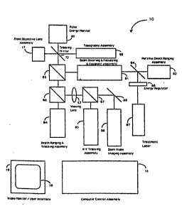
Figure 1 is a block diagram of an instrument or workstation for
performing preeision laser~ surgsry in accordance with the principles of
.:
~ 1
;, :
~.
'`'1~
,'.S1
"''1
. , ~
WO 93/16631 PCTlUS~3/0,1~7~87
3 2
.1 ths invention. In Figure 1 the workstation is config~r~d ~or ophthalmic
, surgery.
... . . . .
Figure 2 is a block diagram of the instrument or workstation indi-
5 cating the path of th~ laser ener~y pulse as it propag~tes through ~he
,. system along with the functions of control and information flow among
various optical components, detectors, and oontrollers for monitoring the
energy of the laser pulse and maintaining ths emission within prescribed
narrow crror toierances.
. , .
., .
Figure 3 is a block diagrarn of the path ~or light traveling from and
back to the depth ranging or Z-plane tracking means, together with the
i~ loop for information flow to ths computer coontrol means and back to the
~ position means.
i:
~,
..,j , .
Figure 4 is the blook diagram showing the light path from the paral-
iax ran~ing assembly to the eye and the control path from the imaging
video camera to the video: monitor display means. The light path ~rom the
~,: eye back to the imaging cam~ra is also indicat~d in this Fi~ure.
;~: Fi~ur~5 is a~block diagram of the workstation in which the light
paths and contS~o~ io7ps for the 3(-Y place tracking means are shown.
,
, ~,
. . J
Fi~ure 5A shows the image of the iris incident on the two quadrant
~5: detecto~ used in a preferred~embodiment of the sensor for X-Y tracking.
~::
, . .
~ . :.
`5'i:
f~ wo 93/16631 pc~/lJss3/ol787
Y ~ ~
33
Figure 6 is a block diagram indicating the interplay of the imaging
.,
means with the video monitor display.
;~ ~
,, ~ .
~ Figure 7 is another block diagram indicating the iight path between
.
S the topo$graphy assembly and the eye togeth~r with the control loop and
.j
:. interface with the video monitor display. The displays generated by the
topography loop depicted in this Figure are overlayed over the live im age
shown in Figure 7 by the computer control assemlbly.
. .
O Figure 8 is a scale drawing of one embodiment of the instru m ent of
, .~ .
present invention.
`. Figur~s 9a through 9c represent three perspectives of an artistic
i ., s
~i~ rendition o~ an ergonomic configuration of the workstation. The system
. .
5 was designed to accomodate the engineering subassemblies in a maximally
compact manner while providing a larg~ amount of clear space for the
~, .,
patient.
.,.~
, 2
Figure 10 is a detailed block diagrarn illustrating the functional
; 'Q: interdep~ndence among the various optical subsystems.
.,.
Figure 11 is a block diagr~m showing the se~usnce of control and
information flow from the user interface elements to the firing of the
~s
~ ~ laser.
.,
-..~
., .
.~i
;.~
-.~
.~
; -
~,
WO g3/16631 P~/US93/0~ 7
'3 ~ 4
Figure 12 is a photograph of a user interface screen showing a se-
iection of computer generated patterns which can further be modified
using "CAD/CAM-like" editing functions, such as are contained in a "utili-
. ties" module.
. .
Figure 13 is an illus~ration of a user interfacs screen showing awindow of a sample "treatment" menu used to select treatment ey~ seg-
ments1 set lesion shapes, choose operating parameters corresponding to
the template designated procedure and other functions.
'. '
Figure 14 is a photograph showing the same sample template as
Figure 12, and highlighting an example of a pull-down "set parameters"
menu.
',
Figure 15 is a topographical representation of a three dirT~nsional
ey~ surface as seen from thP user/int~rface scre~n, highlighting a sample
"diagnosticsn module.
.j
~ ,
In ~he drawings, Figure 1 shows a biock diagram for the fundamental
jl .
assemblies of a GOmplete precision laser surgery and/or diagnostic/ana-
~j Iytlc~l instrument 10 in accordance with the principles 91F the present
3 i~nt~on, }n` the form o f a workstation~ Not shown are the support station
'5 housing the video monitor~ means, the power supplies, the fir~-
on~roUsafe~ switch and other accessories for the workstation.
;
WO 93/16631 PCI/US93/01787
~, .
d 3
''i.
~:, Althou~h the system, apparatus and method of the invention are
illustrated and disc~ssed with refercnce to ophthalmic surgsry and diag-
nosis, it should be understood that the invention encompasses other typ~s
.~ 5 of medical dia~nostic and surgical procedures, as wsll as non~msdical
., operations (e.g. semiconductor processing, such as precision wafer fabri-
'~' cation, short repair using lasers and other microm~chîning techniques).
. . ~
The ins~rument and system 10 of the invention include controls 16
O for a vision system and laser firing, enabling the surgeon/user to survey
the topography and internal features of the tissue ~o be operated upon (the
eye in the illustrated workstation) via a video ~eans 19j and, via the
computerized control means, to precisely control the timing as well as
the direction, depth and spatial pattern of ~iring of a laser b~am in three
dimensions. As wili be~explained below, the surgeon may control the fir-
ing of the laser with 'ttemplates- which can be superimpos~d over an im-
age of the tissue being operated upon,: and which enable an autornatic
;~ tracing of a desired faser :firing patt~rn based upon prior experience or a
sLlr~eon's insights with similar surgical proceduJes. The templates may be
pre-pro~rammed or generated anew for each patient, as the case requires.
... ~: ~
The system al~o includes a ~inal objective lens or focussin~ l~ns or
fr~nt Jens 17 (an element of th~ microscope assembly, as explain~d be-
ow3, tt~raugh which images are taken and through which the laser beam is
'5 directed at the subj@ct tissue. In a preferred embodiment of the system,
an axial iiluminating; light beam~ may be projected at the tissue through
~, ~
,~
.:;
, ..
~ ~,
:
~,...
,.,,~j .
~,. .
WO 93/16631 Pcr/uss3/(l~787
,9~
~, 3 6
;
the topography assembly 98 and the final objective lens 17. In other em-
bodiments of the present invention, an off-axis slit illuminator, providing
'' a ribbon-shaped illuminating light beam, may be used to augument and/or
replace the axial illumination technique, (see Howland et al., Noninvasive
5 Assessment of the Visual System Topical Meeting, Santa Fe, Feb 4-7,
,s
i;~ 1991) depending on the particular kind of surgical procedure and error
tolerances required thereof. The instrument 10 may contain, in addition,
,,; ,, .
'~; the therapeutic laser, 87, the surgical microscope, 86, an X-Y tracking
'. assembly, 85, a depth ranging microscope, 84, a parallax depth' ranging
.... .
0 assembly, 82, various illuminators, and the beam stsering and focussing
assembly~ 81. Ali of these assemblies share an optical path defined by the
final tracking mirror 72 and the iens 17.
The tracking~mirror 72~represents a key element in the system, in
S that It is in the path of light (whether transrnitted or reflected), ~enerat-
d and/or acquired by~all; the various subassemblies of the workstaticn,
excepting only the slit illuminator (of the alternate embodiment, not
~: shown in Figure 1).~1n aiternate embodiments of the invention, the track-
ing~ mirror may be ~driven~e~ither ~piezoelectr~cally or electromagnetically.
'0~ A piezoelectric driver~uses the change in shape of a quartz crystal in
response to a electric~;current to move the mirror. An electromagnetic
driver uses a coil of~ wire in a magnetic field which is made to move by
pas~ing an electric current thrcugh''the coil. The electromagnetic driver is
simiiar in function to~a voice coil of an audio speaker. In either embodi-
)5 ment the speed (or, more~accurately, the acceleraUon) of the entire
:
i, ~
.;~
,~WO 93/16631 PCI/US93/01787
3 ?3
37
:
tracking system is limitsd by the response of the drivers and the mirror's
moment of insrtia.
.
Most of the major components and subassemblies, shown in the block
. 5 diagram of Figure 1, are disclosed scparately and have been incorporated
herein by refercnce. However, the combination of these separate inven-
,
~i tions into system 10, the methods by which they can be made to work in
concert as an integrated us it, and the snhanced capabilities this entails in
a surgical environment are the subject of the pres~nt invention.
For example~ the topography technique requires establishing precise-
.'~ Iy ths distance from the surface to be rneasured to the appropriat~ princi-
pal plane of the front focussing l~ns. Whereas there are several metho~s
for establishing said distanoe, the modified confocal technique described
by Fountain (copending U.S. Patent Application Serial No. 655,919) repre-
sent~ a pref~rred em~odiment of such a measuring technique, incorporated
., ~
by reference into ~he present invention. Since in surgery the targets are
live tissue and are continuously in moti~n, to achieve high levels of accu-
racy requi~s that :the surface to bs measursd by way of the topo~raphy
;1 0 assembly also remain stable with respect to ~he measuring sensors locat-
ed witt~in ~he topography assembly 98, the zoom video assernbiy 86, and
the known ~ocal point cf the laser 87. This is achieved by continuously
adjustin~ the position of the final focussing l~ns 17 along the axial~direc-
,
~1 ~on as further described by Fountain (per above~.
`~3
~` :
Wo 93/16631 ,~ Pcr/uss3/olJt~7
,~ ~ ~ 38 i
Figure 2 shows the light path 71 as it emerges from the laser 87,
" i
passes through the external energy regulator 83, is expanded and directed
in the beam steering and focussing assembly 81 as further described by
~, Fountain et. al. in copending U.S. patant application Serial No. ~ 4 and
5 is aimed via the tracking mirror 72 and through the front focussing lens
s, 17 onto the prescribed target site. In a preferred embodiment of the in-
''5'~l vention, the tracking mirror 72 will have an optical coating which will
. "
permit a small portion of the laser energy to continue through the tracking
mirror along the path 73 to be detected in the energy monitoring assembly
0 80, as depicted in Figure 2.
The pulse energy sensed in the energy monitoring assembly 80 is
e!ectroni~ally relayed ~to~ the computer control assembly 16 which in turn
~ ~ analyzes the output~ energy from the iaser 87 and adjusts the proportion of
,~; ~ 5 the iaser energy of subsequent laser pulses to pass through the energy
regulator 83. ~ln an embodiment of the present~ invention, the energy regu-
iator 83 is a polarizer;~adjusted ~to be 'crossed" with the polarized laser
pulse, preceded by~ a~ rotatable~half-wave retardation plate. The enérgy
''`'i~! monitor 80,~consists~of an~integrating sphere and detector which can
;)0 record energy on a pulse-by-pulse basis. The energy detector calculates
weighted ~ exponential ~movin g averages, modified with a weighting factor,
as well as the rate~of change of the running average. The accuracy of
measurem~nt of the pulse energy is ~within 5%, based on calibration
against~standard energy meters (e.g., Molectron, Scient~ch).
.~.. ~ :
l.i
~: ~
. wo ~3/l663~ ) v~ "~ v. pcr/lJss3/o1787
39
In a preferred embodiment of the system 10, the steering, focussing
` and aiming subassembly 81 may consist of a beam expander 22 that pro-
vides depth of focus variations through change of collimation, and a dual
set of Risley prisms (also known as Herschel prisms) 21 to steer and aim
l~ 5 the beam, as described in detail in U.S. patent applica~ion Serial No. ~33,~4
.j The beam expander may comprise a set of lenses 23, a s~epper motor
41 and a slide 43, with 75 mm traverse corresponding to 25 mm in th~
eye. Beam focus accuracy to within 10 um can be provided in this manner,
based on standard optical components. The Risley prisms are selected as
0 preferred means of beam steering and direoting because of lower moment
of inertia and short~r lever arm as compared to alternatives, such as
;1 ~ gimballed mirrors. The lower moment of inertia inherently allows faster
aiming ~which is enhanced~ by the use of cylindrical coordinates, these
~ . ,
i, being more natural for the eye than Cartesian coordinates), while the
`~ ~ 5 shorter lever ;arm permits~ aiming~further off-axis without beam-clipping (vignetting) at the aperture:of th~ objective lens 17.
in:~a preferred~ embod~iment of the invention, the surgical laser 87
e:mits radiabon in the ~vlsible wavelength range to take advantage of the
'0~ ~ tran~smissicn~properties:~of: visible~ light in the Qptioally clear tissues of
the human eye. One:~ preferréd~ embodiment of the invention uses a fr~quen-
:: ~
cy doubled Nd:`(AG laser, producing sufficiently short duration pulses t
shorter than a few hundred~nanoseconds, and preferrably shorter than 10
nanoseconds) to iimit~the~amount of energy required to ionize material as
5:~ discussed further below.
,3: .
`.,
;~ ~
. ~, ~
~3 PCr/US~3/~ 787
, ~0
., .
In alternative embodiments, thP laser 87 may be one of several
types of flashlamp- or diode-plJmped solid state lasers (such as, Nd:YAG,
~q Nd:YLF, Ho:YLF, Er:YAG, alexandrite, Ti:sapphire or oth~fs) operating in the
''3 fundamental or a frequency-multiplied mode, a serniconduetor laser, or an
5 argon, excimer, nitrogen, dye, or any of a host of different lasers, or
combinations thereof, currently avail~ble or in development. The present
invention can b~ used with any of a wide variety of lasers by specifying
different coatings where necessary for the optical surfaces. A quartz and
magnesium fiuoride focusing element is available as the element 17 to
0 accornmodate ultraviolet lasers whether they be excimer lasers or fre-
quency shifted solid state lasers. One of the features of the present inven-
tion is that it is not laser specific, but represents a surgical instrument
intended to enhance the efficacy of any therapeutic laser. The laser 87
preferably produces a pulsed beam which is controllable as to the level of
5 energy per pulse, pulse~ peak power, and repetition rate. For ophthalmic
~;; applications which do~ not seek to generate laser lesions below the front
~; surface of the cornea,~ or wherever incislng ~the eye is an acceptable option
as a prel~minary or;as part of the~ proce~ure, then excimer lasers, holmium
las~s, carbon~dioxide~ lasers~ or some other ultraviolet or infrared lasar
'O; may an acceptable modality. In one embodiment of the present invention,
the surg~on is not ~restricted to surface effects or to ineising the eye.
With the ~same visible ~wavelength laser (for example, a frequency doubled
;~ Nd:~AG), the surgeon can select any tissue depth (whether on the eorneal
~; ~ surface or below, whether on the posterior lens capsule or in the lens
'5 nucleus) ~at which to generate an effect wlthout the neeessity of
exchanging~ laser modalities~ for different eye segments, provided there
~:
~.
WO ~3/16631 ~ 1 ;3 V ~ 3 ~3 PCr/US93/01787
. - 41
:,,
;; remains an optically clear path to the targeted layer in the corresponding
:' . .
vlslble range.
~'' ...
In the cvent a non-visible-wavelength laser beam is used (e.g.
~, 5 strictly for ablating the front surface of the oornea, or strictly for coagu-
lating blood vessels in the retina, or strictly for photodisrupting rnem-
`i branes on the posterior capsule) some variations in the optiGal configura-
tion of the system 10 will likely be requir0d.
. .
.,
'id, O Figure 3 shows the information path ~or the depth ranger assernbly
84 that measures the distance from the front focussing lens ~7 to the
.,
`1 surface of the eye 69 and continuously adjusts the position of the front
focussing lens 17 along a path 88. In a preferred embodiment of the
present invention, the path length 88 over which t~e front focussing lens
;;~ 5 is adjusted is 5 rnm. The system comprising subassembly 84 together with
, ~ lens 17 and the int~rvening optics~ is sometim~s referred to herein as the
~: confooal microscope. It uses optical elements in common with the other
, ,j
equipment in the system 10, namely~the tracking servo mirror 72 and the
beam splitters 65 and 66. The focusing lens 17 is adjusted as to focus,
'0~ along` a Z axis, in response to.shifts in the depth of the subject tissue
feature, so that the system~ always; returns to a focus on ~h2 corn0al ver-
ex 56 ~the part of the cornea that is closest to the objective lens).
Included in the depth rangsr assembly 84 are depth tracking or "Z-
'5 axis" tracking sensors~ 50: which detect a change in location of the surface
6~ as described by Fountain in a copending U.S. patent application (Serial
., ~
.....
,"~,
;.
;.
.
,, -,.:
'
, . . , , , . .. ,, .. . . ~ ... . . . .
WO 93/16631 PCIJUS93/~ ~7
4 2
No. 655,919, incorporated by reference herein) and relay the information
to the computer control assembly 16 which computes a new desired posi-
tion for the front objective lens assembly 17 and issues instruction to a
motor drive to relocate said lens assambly 17 to the desired new position.
5 A closed loop is thus described which incorporates the live movements of
the eye surface within the decision process of adjusting the focal point of
:~ lens assembly 17, to within giverl tolerances. In this ~mbodiment, the
capture range for axial acquisition is within ~/- 0.2 rnrn and tracking
rates in excess of 40 Hz are within the servo loop capability for maximum
0 ranges on the order of 2 rnm.
Since mirrors and beamsplitters 64, ~8, and 72, tog2ther with beam
splitting cubes 65, 66, and 67, link the other assemblies of ~he system 10
`~ into a common axial path passing through lens focussing assembly 17,
5 they can all be ref@renced to the lens assembly 17 as if the distance be-
;, .
tween lens 17 and eye surface 69 were to remain constasnt. This is a major
simplification in the manner in which eye surgery can be perforrned in
that the surgeon need no longer be continuously monitoring eye movement
to verify a constantly changing focal position within the patient's eye.
.
~j
For procedures wher~ the targeted tissue layer~ lie posterior to the
cornea, the surgeon/user will have th0 use of the parallax depth ranging
ins~rument 88 as shown in Figure 4. This ~ssembly relies on the intersec-
tion of two beams of light (from, e.g., a He-Ne illuminator laser) oonverg-
~5 ing to a comn~on point on a giv~n surface. In one embodiment9 the parallax
,~,
ranger allows mapping of a mesh of points, acquired through judiciGus
,. `
.
' rW093/16631 PCI`/US93/01787
43 ~ v
~, adjustment of the zoom camera to short depth-of-focus (maximum magni-
fication), which, along with corresponding variatjon of the focus on the
parallax ranger, produces a saries of diffraction limited spots on the
structures behind the cornea (iris, lens, etc.). In this manner, the resulting
5 surface will define a desired template.
. "
The inclusion of a parallax ranger within the instrument 10 over-
.,!,~ comes difficulties commonly associated with specular reflection tech-
niques used for detection of the location and measurement of ocular fea-
0 tures. Basicaliy, only the tear surface layer overlying the corneal surface
. epithelium is usually detectable and rheasurable by specular light refiec-
tion techniques. The reflected light signal is generally insufficient for the
extractioll of topographic information of the endothelium surface of the
; ~ cornea (~0.02% r~fle:ction versus 4% from the epithelium)~ let alone for
, .~
'~ 5 charaoterization of the: three dimensi~nal shape of the anterior and poste-rior capsules of tha crystalline ~lens:of the human eye. The parallax ranger
unit provides th~ surgeon/use~r:with the option of using a combination of
~: standard techniques which rely on images of a~target site. Thus, the sur
geon/user:can identify,: to :within th~ inh~rent error tolerances of the
0 technique, when the Instrument is focussed Oll a given surface. The precise
focal point of the beam can then be varied by alt2ring the inoomin~ beam
divergence by way of def~ussing a beam exp~nder means 22 (included
within assembly 81). By redefining the: origin of a given procedure to coin-
cide with the depth at which ths parallax ranger is focussed on a surface,
'5 this n~w identifi@d :surface becomes ths reference surfac~ for perforrning
a ~ur~ical procedure. Via the user interface ~See Sklar et. al., U.S. patent
..j,j
. ,! ~
, :,
WO 93/16631 PCI`/US93~ 7
44
applications Serial Nos. 307,815 and 475,657, incorporated by reference
herein), the surgeon/user can then define lesion templates or confi~ura-
tions to be performed at a given depth with respect to the new identified
surface.
Similarly, the motion of the eye along a plane perpendicular to the Z-
axis of the front focussing lens assembly 17 also needs to be stabilized.
This is achieved using the X-Y ~rackin~ path shown in Figure 5. Intrinsic to
any tracking sch~me is the choice of what is to be tracked. If the eye were
'h 0 a non-deformable body, then any landmark on or in the eye would suffice
.. .
for defining the mo~ion of said materi~l. However, th~ eye neither moves
nor deforms as a rigid body. Consequently, in order t~ de~ine the location
of a moving tissue layer within the eye, the tracking landmark must be
located contiguous to the targeted tissue and should meohani~ally respond
5 in a manner similar to the t~rgeted tissue.
~' ,
` ::t
For corneal refractive sursery, the eye limbus at the radially out-
ward edge of the cornea satisfies these constrain~s. It has lthe advantage
of not only moving with the cornea -- inasmuch as it i5 a part of the cor- -
~: '0 nea -- but~ since it likewise is connected to the soJera, it wiil not respond
as dramaticalJy to the ~ transie:nt deformations associated with the miero-
sur~ery. In effect, pursuing the motions of the limbus will allow the
J~!
. computerked control system to replicate the template pattern presented
on the display by the user interface, even thou~h the ey~ surface wili be
'5 a~preciably defonning during the course of the surgical procedure.
;,ï
I ~
~!,i
i`,~i
,~
., ~ .
f-_~WO 93/16631 PCI`/US93/011787
; 45
In one embodiment of the invention, the transverse X-Y tracking
detector consists of high speed quadrant detectors and a microprocessor
such that updated position information is fed to the tracking mirror at
frequencies substantially higher than the repetition rat~ of the laser, or
the frame rate of the imaging camera. The response tim~ of the tracking
detector and prooessor shoulci be sufficiently faster than the rnaximum
i~
repetition rate of the laser, so that laser firing can be disabled, if neces-
sary. The response time of the detector and processor should also be
higher than that of the driven tracking mirror, which must be capable of
O sufficiently high acceleration and velocity to compensate for the fastest
motion possible by the intended target.
In Figure 5, light from the limbus 70 passes thraugh the objective
lens assembly 17, is~re~lected by the X-Y tracking mirror assembly 72,
,
~5~ and is propagated via the beam splitting cubes 65 and 66 through the
viewing~ iens 63 to~ be~ reflected off beam splitter 67 to the sensors of the
X:Y tracking assembly~85. In one preferred embodiment of the present
, ~
s invention, à~spatially~sensitive sensor 50 comprising two quadrant detec-
; ~ tors is used to track~an~image of the outer rim ~at the limbus) of the iris
o 32. ~s shown in Figure~5A, the image at the quadrant d~tectors (each with
3~ ; four q~!adrants, 35, in~ th~is~exam~ple) will then consist of a bright lune-
shaped field corresponding to the sclera 33, adjacent to a darker field
representing an image~; of the~ iris, 32. The very dark central core which is
an~ image of the pupil~34, is~not captured by~the detectors, as Figure ~A
'5~ ~ illustrates, ieaving a~single~sharp boundary to track. With various ce!ls of
the ~quadrant~de~ector~oonnected through differentiai amplifiers and nor-
. .
,. ,i
Wl) 93/16631 PCr/US93/QJ~7
~ ~ 3~33~ 46
. .
rnalized by the sum1 the resuitant signals are sensitive only to the posi-
-~' tion of the centroid of illumination of any of the above patterns. Quadrant
, . .
deteotors integrate the image illumination striking each quarter ~f the
,, detector face. The luminosity impingent on the detector faces will then
5 generate voltage differences corresponding to the integrated differences
in light hitting the detector parts. A change in background light intensity
~ will be ignored, as the incr~ase across the four (or eight) quadrants 3~ of
`, the detector face will remain the same. Voltage sums and differences
,, j
among the quadrants serve to establish the relative direction of motion
^i,~ Q between two contiguous readings of the limbus position. A shift in inten-sity at the sensor is thereby traced to motion of the limbus. These dedi-
. ~
cated quadrant detectors record voltage changes extremely rapidly and canobserve and quantify contrast changes and edge motions in less than 100
microseconds. In alternate embodiments, similarly fast but more sensi-
~ 5 tive position sensing detectors~ are used in this application, yielding en-
; j ~ hanced performance at~ even lower~ light levels.
The voitage change informaUon is relayed to the oomputer controlassembly 16 wher~in the~actusl coordinate shift is calculated. Control
'0 ~assembiy 16 then determines the angular corrections ~o be relayed to the
X-Y tracking mirror assembly 72 and aGtivates a voice coil or other elec-
tromagnetic drive assembly to pivot the orientation of mirror 72 so as to
stabiiize the X-Y motion of the limbus 70 with respect to system 10. Thi~
embodiment of a tracking system uses entirely analog signals and tech-
~'5~ niques to achieve traoking~ and can be made to work significantly morerapidly than even the fastest involuntary motions of the eye.
.~ .,. ~
.,^; :
.. ,. ~
.t
,;d
;: -
~ WO 93/16631 PCI~/US93/01787
; 47
'
,
In one preferred embodiment of the invention, the range of use, or
travel, is 2 millirneters in the X-Y plane. For ophthalmic appli~ations,
where the principal motions of the eye are rotations, it is often prefera-
. . .
5 ble to define the range of use in terms of angular sweep of the eye. Forexample, an angular motion of the eye of 5 degrees falls weli within the
domain of use of the X-Y tracking system. For a ~ighted human patient, it
has been estimated that such range o~ use will acquire an eye looking at
,1 an ima~e point lo~ated in ths far field ~relative to the patient) and situat-
~I 0 ed along the optical axis of the~ apparatus.
";
~- The transducers of the tracking system adjust the position of the X-
Y mirror along two rotational axes at accelerations on ths target in ex-
,i
~ cess of 20~ microns~per millisecond for full amplitudes of over 2 millime-
i ~ , ;
5 ters, based on microprocessor-provided information reiating to the new
3 ~ ; location of the s-me tissue ~ ~
The eye surface~69 may~be displaced in translation and/or by rota-
tional motions centersd on~;the globe of the eye; because the X-Y tracking
'0 ~;; mirror 72 rotates about~ a ~point within its assembly that is different from
he~eye~'s center of ~rotation, a~desired change in X-Y tracking mirror posi-
~: tion also requires a~ correction of the X-Y axis position of the depth rang-
ing and tracking assembly~84. Consequently, the algorithm which pi~ots
the X-Y tracking mirror 72 along paths 61 and 62, also must relay instruc-
5 tions to the ~omputerized control system to adjust the dspth tracking and
ranging assembly 84 so as~ to~ maintain the correct orientation. The pre-
~ .
.~
,.` : :
.
VVO 93/t6631 P''~/US93/~7
G~,r~ 4 ~'f
ferred methods to achieve this correction use a compansating mirror 60
within the Z-trackinf~ assembly (not shown in Figure 5).
' , ,
The tracking system system has ths advantage of being able to find
an absolute position ofn the target even after a temporary loss of tracking.
For example, if a surgical procedure is in process and an obstacle, such as
a blinking eyelid in many ophthalmic procedures, interp~ses thfe tracking
image such that the procedure is interrupted or temporarily aborted, the
;..
. tracking system will automaticalffly store in m~mory the last posîtion in
. ,,
0 the firing seqfufence so ~hat once the target is a3ain reacquired, the~ exact
~ iocation off the next point ifff~ffff ~he firing sequerfffce can be determined auto-
!::;' matically and the seffrvo mirror be repositionfefdffff accordingly.
:
Figufre 6f shows the surgical microscope loop. This subassembly in-
5 cludes the low-light-level camera and the zoom optics. Tha camera pref~-
erf~bly comprises an intensified video camsra, for examplfe a silicaffn inten-
~ sified targfet (SIT) tube camera. Alternatively it can be a conventional
:~ vid~so camera in Gombination with a microchannel-plate intensifierO In
sither evffsfnt the camera's sensitivity preferably is about 1000 times that
; l '0 of a normal video camera,~ enabling ths system to look at weakly scatterefd
light and targets poorly illuminated for the desired levels of high magni-
.~;f- ficatifff~n at large working distances.
, . . , ~
,.. .
In a preferred emffbodiment of l:he ,oresffuf~nt invention, the system uses
' 5 a combinatisn of specular and scatterfed light techniques for detecting arffffd
identifying diffusely reflecting surfaces, specularly rfeflecting surfaces,
: ,1
,. .
, . f
. . f
.,
-, ~
~0 93/16631 P(~/US93/01787
; ~3~7~sq~
I 49
surface displacements, features, and shapes of the patient's tissue. This
iS particulariy useful in the eye where it can prove difficult to differenti-
ate between the amorphous tear iayer anterior to the eornea and the
~i structured epithelial surface layer of the cornea. Even the cell walls of
;15 the endothelial cells of the cornea or of the anteri~r lens capsule will
'''1
;~ scatter light. The intensified surgical microscope can produce an image of
these actual cells by forming an image composed by detecting scattered
Iight. The surgical microscope, as well as the tracking camera, can sub-
stantially exclude specularly~ reflected light by cross polarization of se-
0 lectively polarized illuminators. Other methods for reducing specular
reflections preferentially to scattered images are also possible.
The microscope optics are designed to~provide flat field, anastig-
matic, ~achromatic, nearly diffraction limited imaging with optical magni-
;5 ~ fication zoomable approximately over a 15-fold range of, say, 15X - 200X.
~ J .
The magnification is~ adjustable and is typically~ selected to correspond to
the largest magnification which can still be~; comfortably used for situat-
ing a lesion (that is,~the~ smallest field of view which can be used when
magnified across the fixed display~ size of the video monitor). For exam-
I;i`~ ?~0 ple,~ for corneal refractive; surgery, where the surgaoh needs to observe
the cornea ~from ~ limbus~;to; lirnbus,~ this corresponds to a field of view of
sY; approximately 12 to 14 miliimeters. At the screen, the zoom optics allow
for adjustable magnification in the range of about 15X to 200X, for exam-
ple. This enables the~surgeon to view a very narrow field, on the order of
'5 a~ millimeter in width,~ or a~much wider field at lesser magnification. ThiS
is useful in enabling~ the surgeon to assure himself that he is aimed and
.; ~
's'~
.~
~s
.... . ......
WO 93/16~31 PCI/US93/0~7
~'d~ `
focused at a particular desired region. Zooming can be 0ffected through
use ~f a joystick, trackball, mouse, or other pointing d0vice 42 to access a
scroll bar in the user interface. . .
The function of the viewing mirror 68 shown in Fi~ure 6 is to move
the surgical microscope image on the screen to the left or right er up or
dewn, independ~nt of the aiming of any other subsystem.
Figure 7 shows the light path for the topography assembly 98,
0 which provides a three dimensional mapping system directed at the sur-
face of the target, e.g. the eye of the patient. In a preferred embodiment of
the system 10 ~as described by Sklar in lJ.S. patent No. 5,054,907 and
further extended by McMillan and Sklar in copending U.S. patant application
Serial No. 656,722 and by McMiilan et. al. in ~opending U.S. patent applica-
tion Serial No. _, p~r ref. No. 266P cited above, all of which are in-
eorporated herein ~by reference),~ ~he subassembly 98 may comprise a light
projector ~5 includin~ an internal: profilometry source 90, an illumination
mask 96, an optical collection system 94 and a profilometry assembly
.
consisting of, e.g., an adjustable ap~rture 99 and a CCD camera 97
'0 equipped with a frarns grabber. In one pr~ferred embodiment of the inven-
tion, the light projector 95, using the profilometry source 9Q, projects a
predetermined pattern, such as an array of dots arranged into rings and
radial spokes convarging to a common center, onto ~he tear layer of the
eye. :The refleeted images of the predetermined patt~rn are collected by
~: '5 the optical assembly 94, which may include a set of plates to correct for
; any astigmatism induced by the tracking mirror 72 and any other interior
I,
- ~wo 93/16631 Pcr/us93/0l7%7
5 1 ~ 8 ~
mirrors, fed into the profilomater camera 97 throu~h the aperture 99 for
analysis. By contralling the angle of acceptance of the light bundle from
each virtual image, the adjustable aperture acts as a spatial.filt~r, pro-
viding a physical representation of the source of paraxial rays through
trade-offs between resolution and brightness. The camera includes means
Y to digitize and electronicaliy enhance the images. The signals are fed to a
~, microprocessor which performs preliminary displacement analysis using
software means (embedded within the controller 16) based on mathernati-
~i cal morphological transformations as described by McMillan and Sklar
,~ 0 (copending U.S. patent application Serial No. 656,722). The transforma-
,~ .
'1 tions comprise a solution of a set of coupled differential equations,
whereby the local normals and curvature parameters are computsd at each
il data point so that the surfacs can be computed to within the measur~ment
accuracy, and subsequently displayed on the video screen 20. The methods
~:~ 5 of light projection and profilometry permit the system 10 to operate with
j~ low intensi~y light signals to enhance safety and patient comfort while
,..
~ ~ extracting significant: signal levels from the noise back~round.
!~
In other embodiments of the profilometry assembly, alternative
,.,
; '0 projection techniques may ~be utilized in place o~ or in addition to the
mappiny and projection~ :means described abov~. In one embodiment, an
.' external profilometry source 89, consisting of an array of LED's projects
a pattern of dots onto the eye in a manner describ0d by McMillan et. al. in
copending U.S. patrent application Serial No.
. referenced
. . ~
:: above as 266P. In this embodiment cunrature measurements of the anteri-
, 1
.~ .
!,. .
WO 93/16631 PCr/US93~7
~3~9Q~ - 5 2
or surface of the cornea can be obtained sxtending up to 8 mrn in diameter
around the center. Other techniques based on off-axis illumination may
utilize, ~1.9.7 a slit lamp illuminator 77 to obtain measurements ~f the
thickness of the cornea, the depth of the anterior chamber and/or the
5 thickn~ss of the lens (the latter coupled with standard keratoscopy
methods to correct for oorneal curvature). Mounting the slit lamp at a
fix0d location relative to~a CCD camera (such as 97) and rotating the en-
tire structure around a centar axis would also provide a method to collect
global corneal data (out to the limbus) yet without saorifieing local accu-
0 racies, given the simultaneous 3D tracking capability already contained inthe system. In ~his manner, the doma`in of topographic measurements can
be extended from limbus to limbus while providing pachymetry data as
well. Alternatively, topography methods based on P~onchi grating in con-
junction with Moire interferometry, or advanced holographic t~chiniques
5 as discussed by e.g., Varner (in Holographic Nondsstructive Testing, Aoa-
demic Press, New York, 1974, pp.105) and by Bores (in Proceedings of
Ophthalmic Technologies, SPIE Vol. 1423, C.A. Puliafito, ed., pp. 28, 1991)
: may be utilized in future embodiments of the system 10, if warranted for
I ~ ,
sp~cific interv~ntions.
.
:: Figure 8 is a~schematic~optical layout of a preferred system of op-
tios for the instrument of the invention In Figure 8, a Schneider Cinelux
Ultra 90-mm focal length U2 lens is combine~ with a ~;chneider Tele-
I ~
Xenar 360-mrn focal length ~f/5.6 lens, matching conjugates to form a
5` 4X/0 24 numerioal aperture (N.A.~ Uobjective lens" 17 with a wsrkin~
distance of 59 mm This type of design embodies a key feature of the
~`W(~ 93/16631 ~ 9 !1 c~ PCr/US93/01787
53
present invention, whereby a comfortable distance between the patient
and ths optics is implemented ~sufficient to provide the surgeon/user
enough open clear space to easily fit his hands between the fron~ "objec-
tive lens" 17 and the patient's ey~/target surface 69) while maximizing
the aperture ratio o~ the system. A beam splitter between the front and
back lenses of this "objective lens" allows the 90-mm lens to aiso serve
as the final focusing lens for the laser. A Schnaider Xenon f/2 !ens, with
28-mm focal length, relays the image to the camera contained within
subassembly 8~, with magnifications zoomable from about 0.4X -5.4X in
0 this embodiment of the invention. An appropriate field lens 58 is usied to
provide uniform illumination across the image of the rnaximum 1 5-mm
field of view at the object (eye) and to reduce the magnification. Zooming
can be accomplished by computed-and-steppsd motions o~ both the zoom
lens 59 and the camera. The totai optical magnification is thus zoom~ble
', 5 in this embodiment from:~about 0.8 to 11. With the irnage inciderlt on a 2/3-
s inch video detector and displayed on a thirteen~inch (diagonal~ rnonitor, an
additional 19X ~video magnification is gained, thus a maximum maynifica-
:tion from the :target to~ the screen of abo~ut 200X is achieved.
:)0 Another important feature of the~ optics of the system of the inv~n-
tion is that the servo tracking mirror 72 actually is positioned inside the
~1 ~ "objec~ive lens" assembly (the final element has been designed to have
y sufficient field to accommodate the small misalignments caused by the
;: tracking mirror). This enables the system to achieve rapid tracking of
5~ ocular features (or ather tissue~fea~ures) in an e~fi~ient and relatively
~,
.1:
WO 93/16631 P~/US93/0~7
2130g~ 54
simple assembly, without moving an entire objective lens in following the
sometimes rapidly moving ~eatures.
The optical system is designed without correction for the aberra-
5 tions of the eye. For work in the cornea no corrections are ne6ded. For
work at image planes located posteriorly to the cornea, such as the retina,
for example, contact lenses 28 (e.g., Goldman or similar) may be used, as
shown in Inset a of Figure 8.
O As illustrated in Figure 8, the illumina~or light beam contained
within assernbly 821 first is reflected o~f a turning mirror 73, then
transmitted through mirror 64, to join substanti~lly coaxially with the
path of the las~r beam along the beam axis 71 (see Figure 2). Both beams
are then steered through the bearn steering and aiming optics in assembly
.;
i, ~ 8î and are reflected off a reflective surface in the polarizing beam
;.~ splitter 65 before being incid~nt the tracking mirror 72. Ttse polarizing
beam splitter 65 ~along with beam splitter 67) effe~tively prevent inter-
;~3i nal back relFlections of ~ the laser pulses from the optics of the system
from damaging or ovenNhelming the sensitive video microscope oamera
'0 con~ained in assembly 86.
!:
~' Also indicated in FiglJre 8 are the optical trackin~ and viewing ele-
ments namely, the depth ranging assambly 84, the X-Y tracking assembly
~' 85, and the surgical microsoope 86, all share the same optical path from
~,
, '5 beam splitter 66 to the eye. Some key design details of the ~-tracking
ass~mbly 84, includin~ the illumination source (such as a red He-Ne taser)
,
.~
r~WO 93/16631 PCr/U!~i93/~)1787
5 !; ~ O ~ 7.~t' ~i
are shown in Inset b. These are described in more detail in copending U.S.
patent application Serial No. 655,919.
As Figure 8 shows, the beams generated by the therapeutic laser ~7
5 and the parallax ranger 82 are coaxial with each other, but the axis of
these beams is not neeessarily coaxial with the axis of view of the profil-
ometer camera 97, the topography illumination sour~e 90 or tha other
tracking/viewing ass~mblies 84, 85 and 86. This is because of directional
steering P~isley-prism sets 21 embedded within assembly 81 which are
O outside th~ optical path of assemblies 84, 85 and 86 but within the opti-
cal path of the parallax depth ranger 82 and the laser 87. The Risley
prisms are steerable via the computerized control assembly 16 under the
control of the surgeon/user through user interface oommands. They pro-
vide means for adjustin~ about the X and Y axis, thus letting the physician
5 seiect different locations for firing the laser as disclosed by Fountain and
:~ Knopp in copending U.S. p~ent application Serial No. 571,244. The two
elements 82 and 87 therefore~ will only be coincident with the axis of
I
view of the dep~h tracking assembly B4 when the surgeon aims the laser
directly :at the c~nter of the fieJd of view of assembly 84. In other in- ~
stanc~s ~hey will sh~re the same "optica3 pathN via elements 72 and 17,
but they wiii :not be on identical axes. The Risley prisms within the as-
sembly 81 allow rnovement :of the aetual airn of the therapeutic la-~er
be~m from the laser 87 to a real aiming point which is c~incident with! the
computsr-:-narated aiming points.
WQ 93/16631 : P~/US93/0~7
56
The set of beam expander lenses 23 preferably ,are positioned as
close as practical to final objective lens 17, and are initially adjusted so
as to expand the diameter of the laser pulse emerging from the laser cavi-
ty and collimate it s~ that a parallel but expanded beam of light emerges
from the lens 22. The expand~d, collimat2d bearn is incid~nt upon the
final lens 17, and the expandsd beam fills the lens to the extent compati-
ble with vignetting for off-axis aiming. Thus, a large-diameter beam is
focused by the lens 17, so that only at the point of focus within the eye is
the diffraction limited pulsed laser beam effective in generating the de-
O sired therapeutic lesions in ~he eye. The depth of the focal point is varied
by adjusting the distance between the t~vo lenses 23, which has the effect
of changing the degre~ of collimation and hence the focus as indicated
explioitely in Fi~ure 8. The surgson's adjustments of the focus of the bsam
via the computerized control: sys~em 16, are superimpossd on top of the
automatic adjustm~nts effected by the tracking syst~sm, and net focus
~, .
~. changes are carried ou~ by the system. This is easily accomplished using
hardware and~ software~ associated with the system which does not in
itself form a part of the :pr~sent invention.
2 ~ ~
i~'Q The decoupling of the aimin~ and viewing functions allows off-axis
,: work, which represellts a major improvement in the function of the sys-
:~ : tem 1û, in that off-axis capability is a mandatory feature for oorneal and
most other applications. Thus, an indspendent mirror 68 is inserted up-
,~ ~ stre,am of assembly 86 to~ allow viewing, while aiming is performed inde-
..
'5 pendently in the c~axiai illumination path using the Risley prisms 21 of
subassembly 81. In an alternative embodiment of the system disclosed
, ~ ,
,f ~ ~ ~
if
~ .
~- . Wo s3/t663l 2 ~ ~ o 9 ~ ~i PCr/USg3/~1787
57
herein, a secondary angular steering mirror 60 ~not explicitely shown in
Figure 8) may be added in assembly 84, to compensate for motion. irnpart-
ed by the X-Y tracking mirror which can, for large enough eye motions,
5 cause tt~e Z-tracking system to "lose lock".
, Inset c of Figure 8 shows some schematic detail of the external slit
lamp illuminator, provided in an alternative embodiment of the system 10
to augument and/or replace the internal profilometry iliumination source
0 9~, and pr~vide ocular thickness measurements as was described above
(see discussion following Figure 7). The slit lamp constitutes the only
element of the system not co~xial with the optical path defin d by the
tracking mirror 72 and the "objective lens~' 17 common to all the other
su~assemblies.
Figures 9a, 9b and 9c show three perspecti~es of an ersgonomic
1 .
rendition of the workstation which incorporates the entire system 10.
The system 10 in this illustrated ernbodiment of the invention is intended
d; for ophtha~mic surgery, with the patient to ~e seated, as shown in Fi~ure
~0 9a, tn a chair 11 with his ~rehead against a forehead rest 12 and his chin
a~ainst a chin rest 13 as shown in Fi~ure 9b. Both forehead and chin rests
are fully adjustable. The surgeon/user is free to stand at a convenient
location where he/she ~an survey the progress of the surgery as depict~d
on the video monitor means 18 (Gontainin9 the video display means 27,
i:
,
.1
i
WO 93/l'f~631 P'CI'/US93/0~7
3~9~ ;6'`3 58
including screen 20) as dopictQd in Figure 9c, while having fdfirect access
and observation of the patient, or to sit in a chair 14. The seats 11 and 14
for the patient and the surgeon, respectivsly, preferably are ful!y adjust-
able with e g., tracks 15 (shown in Figure 9a) for adjusting proximity to
the apparatus and wi~h full hfeight and seat back adjustability.
A hand held system control switch 24 in Figure 9a may be provided
for the surgeon as a safety device which will both fonable the laser trig-
gering means when sufficisnt prff~ssure is exerted on the device 20 ~via a
0 simple toggle switch, for example), or alternativfsly will immediatefly
interrupt laser firing if pressure on the control means 24 is released.
Figfure 10 is a funff,tional block diagram showing the principal com-
ponents and individual cofntrol and informationfal ~eedback functions of the
precision laser surgery sys~m of the invention, all indicated as being
under control of a fcfff-ffffntral processing computer 1~, designfff~d to integrate
and control the operation of the sntire system 1u. The computer may in-
clude a microprorf~assor 140,~ software programstl41 and firmwfare 142 as
indicated in Figure 10, as well as a nufmfbff3r of other cfff~ntrol and indicator
~'0 features ~not indicated) such as thf~f~f enabling (or disabiing) of internal
safety ifnftefrrupts~ a light-emitting diode (LED) ffdfisplay which indicatss
when the tracfking system anfd target acquisition system are opff3rational
and on-target, an LED which lights up when the sys~em cfsmponents have
f - successfully been wsrified to be performing within system sp~cification'5 ranges, an LEl) indicating power is sn, and a dedicated video display func-
tion to assist in detecting :lo~ation of a system malfunction. Note that
'
. ~ .
r~ WO 93/16~531 P~/US93/01787
~J 1 3 0!~
ss
some key functions in the syst~m are carried through dedicated micropro-
cessors 150, whi~h, for simlicity, are shown in Figure ~0 sharing the
same block as the central microprocessor 140. . .
During the start-up phase of the system 10, a complete system veri-
ficat:ion is perf~rmed automatic2l11y without further prompting from the
surgeon/user, including a set of internal diagnostics listing the status of
operational use of the ~rarious assernblies. During this start-up phase, the
assemblies shown in Figure 10 (and Figure 1) are each individually tested
0 for operational status within prescribed tolerances. If all tolerance lev-
els are satisfi~d, th~ user interface screen 20 appears and the system is
enabled for use. Additional safety LEDs acknowledge sufficient pressure
on the laser fire safety interlock in the hand held (~r, foot pedal) safety
device 24, and whether the microprocessor ~enerated template pattern is
~: 5 in: control of the firin~ sequence.
As shown in Figure 10~ the central computer (which receives simul-
taneous diagnostic measurement and tracking information) closes each
control loop through a~ central fire con~rol func~ion shown as block ~00
~0 forming ~ critical part of the computer control assembly 16. This ~ail-safe mechanism is a key feature provided wi~hin the instrument and sys-
t~m 10. Thus, the computer, which direct!y con~rols las~r firing, as indi-
cated by control line 144, automaticàlly interrupts the firing sequence!
; should any of the required operational specifications not be met (such as
:'5 loss of tracking, deviation of th6 pulse energy, etc.). If ail pres0t condi-
tions are met, the computer control ~ssembly enabl~s and fires the surgi-
.
.
WO 93/16631 PCI/US93/~7
3 g d ~ 6 0
cal laser in accordance with preselected templates shown, functionally,
as block 6. The required information comprises confirmation that the
template is still positioned correctly, i.e. that the targeted feature.of tha
eye has been tracked within a presel3cted time allotted, so that the imag-
5 es of the eye remain stabilized. If this confirmation is not sent (or acontrary signal could be sent to signal that tracking is lost), the template
controlled l~ser firing is immediateiy interrupted, as discussed in more
detail below.
0 The user interface shown in a block 19 in Figure 10, communicates
with the central computer unit 16 as indicated by control line 123, though
it may also have some c~ntrols which do not involve the main micropro-
cessor 140. Thus, i~ the surgeon wishes to generat~ a template for sur-
gery, as ~hown in dashed line~ 131, or merely to chang0 the display on the
video screen for the purpose of :sel~cting a different ~pe of presentation,
: or for imposing :a different surgical path ~on the~ s~reen, thesè communica-
:~ ~ tions are carrisd out through the central proeessor unit (CPU)14û (~aken
to include appropriat~ software 141 and firmware 142), which controls
: ~ the computer-generated irnages~on the screen as well as most other func-
'O tions in the system. ~As~such, once the surgeon/user has finally det~rmined
;~ his selection of t~mplate, ~has~ superposed that ~emplate using the comput-
er cvntr~ls 16 onto the posi~ioning diagnostics at the desired location
where the surgery is to be~ effected, and the modifications to the shape lof
the template have bean effected to accommodate for the particular con~
'5~ figuration~of the patient as;observed through the video display means ~7
~: (which includes the screen 20) and the reconstructed target cross-
. ,
~ .
~wo 93/16631 pcrfuss3/o1787
61 ~130~)9J
sections, then the system is set to automatically fire at a discretized
approximation of the configuration selected on th~ video screen 20. Dis-
cretization techniques, computer pattern overlay means, and the.inl:lerent
CAD/CAM software techniques necessary to accomplish this process are
known art and, as such, are not further described. The user's control of the
template is thus indirect, proceeding via instructions received and stored
in the computer memory, which, in turn, generates, processes and stores
template information as shown by control line 121.
'
0 The CPU 140 is connected to a number of other components. For
example, it can send information to an l/~ unit (not shown in Figure 10)
for record ke~ping. The transmissions may include, for example, patient
; history records to be printed or stored.
The CPU 140 can send eontrol signals to a dedicated l/O boards 152
~: which may be used for e.g.~driving motors associated with the steering
isiey ~assemb!y 21, as wetl as for driving X-Y axis adjustments and other
tracking functions through software included in 151. Comrnercially
avallable dedicated ~l/O boards ~are~ capable of handling 16 analog channels
0~ and three digital ohannels ~i~n~ ~the~ currently described embodiment of the
system 10. Thus, one board (in, e.g., 142) can handle diagnostic informa-
tion reiating~ to laser status, position status, tracker mirror status, and
~! ~ other diagnostics which~ may be implemented as needed such as intraocu-
ar tempera~ure, intraocular pressure readings, and surface wave propaga-
~'5 tion measurements~ to enable calculation of the Young's modulus and othar
elasticity constants in an effor~ to determine applicable constitutive
.~ ~
; i
WO ~3/16631 PCI'~US93/0~7
;2
relations. The sensors for these conditions of the eye are not shown in
,s thc drawings, but can be incorporated in the system Qf the invention.
, ' , . .
.` In Figure 10, the surgeon/user indicated at 8 Inter~ction between5 the surgeon and the patient is mostiy indirect (as shown by dashed line 5),
`is via the instrument and system of the invention Thus, inforrnation and data
concerning the patient's tissu0 is ~ed back, indirectly, through the instru-
ment, to the surgeon, via the video display 27, contained within the user
interface 19. The surgeonluser inputs instructions and commands to the
.: O user interface 19 and the user interface feeds back information to the
, user, principally via the video screen 20: This is indicated by a line 25.
t~ ~ :
The pointing device 42~is~indicated in Figure 10 as a key link in the
: surgeonis control of the user ~interface. It is used to control all aspects of5 the operation from generating ternplates to viewing, diagnosing and
treating the target tissue. ~ ~ i
.,
The eye/target 3 :is~ shown as ~sending information to a topography
system 98~(comprising;a~light;~projector 9S and~ topographic data collec-
tion system 77), a viewing/imaging system 86 ~corllprising blocks 46
throu~h 49), and to X-Y ~and ;Z :.~:position analysis tracking detectors 50 and
53 contained within assemblies 85 and 84, respectively. As represented
in Flgure 10, the imaging/viewing system 86 comprises the video micro-
scope 46,~which presents~:the ;tissue video irnage ~exemplified in Figures
'5 ~ 12 :through~15 diseussed below), ~the zoom control 47, th~ aiming viewing
48~ and the focus viewing~means 49. An double-ended arrow ~27 indicates
~ .
.
! -`' WO 93/16631 PCr/US93/01787
. . 63 ~130{~f~
transmission of the video information to the video display maans 27,
forming a part of the user interface 19, and resulting in live video images
4, on the video screen 20. The control arrow 127 between the user inter-
face and the viewing system 86 also indicates that the surgeon may con-
5 trol the magnification of the video microscope depicted in the block 46via zoom control function 47, as well as view selected aim points and
beam focus, all of which comprise parts of the complete assemb!y 86.
The control line 123 from the user interface to the microprocessor
(which indicates the surgeon user's selections made by input controls
other than touch screen), thus serves to represent another user input to
the microprocessor 140 active when the user steers the field of vision
. ~ and the aîm ~f the laser. Such deliberate control by the surgeon will indi-
rect.y control the .aser beam aiming and~focus via the microprocessor,
~5 (along the control lines 113 and 114 as discussed below). Us~r interface
signals to~ the computer con~trol are also used by the CPV to adjust the com-
', ~ puter-generated images a~cordingly, refiecting precisely the desir~d
change In beam focus, imag~ magnifica~ion and aim points.
0~ The content of signals~sent by the microprocessor (GPlJ)140 to the
ideo screen (alo~ng control line 123) relata also to ths computer-
` generated:topographical images acquired as shown by line 101 from the
~, topography system ~8, and discussed further beiow. The CPU also cont'rols
: ~he display of ghe branGhing look-up tables 30 shown on the screen 20, as
~'5: ~ well as other pull-down menus, displays and other pertinent informa~ion.
1;
.
. ,,.i . .
WO 93/16631 PCI`/US93/~)~7
6~,~ 3G~ 4
In Figure 10 information about the eye 3 is shown as being sent to a
block 77 labeled Topography via control line 104. The arrow 102 indicates
the derivation of such inforrnation from the eye via the projection system
95 while the transformation and processing of said information by the
5 topography system 77 is represented by arrow 103. An information con-
trol line 101 indicates processing and feed-back via the Computer control
assembly 16 and dedicated microprocessors contained in 150. The block
77 is taken to include the sensors, CCD cameras, such as profilometer
camera 97, optical coilection assembly 94, aperture 99 and analysis loops.
0 As represented in Figure 10, the functions of a dedicated rnicroprocessor
and programming for this subsystem are included within blocks 150 and
t 51, respectively. The derived information relating to the topography of
: the eye tissues is then :sent to the tracking and stabilization blocks dis-
cussed next. ~
The X-Y position ~analysis and: traoking system (contained within
assembly 85~and described operationally for Figure 5) proc~eds primarily
:~ ~ throu:gh the tracking dete~tors 50 and the servo drive 51, but is also un-
~:~ derstood to: include the servo logic loops and any associated optics re-
';0~ quired~t~ stoer the light~emanating from the images received from thetargeVeye: 3, as indicaîed~:by~ arrow 108, for the said purpose of detecting
and followin~g any movement of the patient's tissue. This information is
~: relayed to the X-Y servo drive 51, via information control loop 109 which,
in turn, controls the :tracking ;mirror:72, as indicated by arrow 116. This:~ `'5 ~: ; logic sequence ~indicates that the detectors: subsystem, after analyzing the
images and determining that a feature~has moved, sends information or
1.
,
~::
WO 93/16631 PCI/US93/01787
) 9 ~ ,
instructions to the servo drive, which constitutes the target tracking
assembiy (along with dedicated processors included in 150). The informa-
tion or instructions can comprise new coordinates for the position of
mirror 72. The target tracking assembly thus translates the new coordi-
5 nates into instructions for the mirror drivers via arrow 116 to the servomirror 72), which instructions may include coordinate transform informa-
tion and commands for the tracking mirror 72 to turn to a new angle which
will again b~ centered on the same features.
i1
O An information arrow 111, shown between the position analysis
tracking detectors and the computer control 16, indicates processing of
~, the information and stabilization of the video images by a dedicated mi-
croprocessor, contained within the units150 shown in Figure 10 (for sim-
plicityj as embedded within the central computer assembly 16. Computer
3l~ 5 processing functions relating: ~to the X-Y tracking unit include appropriate
~:: programming units which are abl~ to analyze data taken by the tracking
!
de~ectors 50 and to determine from the data when fea~ures have moved
and~ to relocat~ those features and calculate new coordinates IFor mirror
~3 position. SQme of these~ functions were described further with reference
'O to Figure ~. The control arrow~ 117 aiso represents feedback from the
mirror assemblies as to~ their ~actusl position, as well as confirmation
that the mirror was physically moved, i.e. that the instruction to the
2~, mirror resulted, where in~icated, in a physical displacement. If this move
does not occur, the system~ioops back to the target tracking assembly
'5 which sends a signal along control loop 144.to disable ~he laser firing. The
important control arrow 144 thus relates to the preferred safety fea~ure
.~ :
,i ..
,, ~
i, ,
"~:
, i
WO 93/16631 PCI/US93/Q,~7
~L3~ - 66
embodied within the present invention The target tracking assembly, if
unable to track the moved feature to a new location within the tirne allot-
ted (which may be as fast as few milliseconds in a preferred err!bQdi-
ment), will send an instruction to an internal fire control 100 to abort
5 firing of the laser, and this command is relayed to the laser power control
via arrow 144 The automatic fire control mechanism representes by block
100 will also interrupt the execution of the template program, vis a vis
the control line 121 in Figure 10 The interrupt preferably lasts only until
the feature is recoversd via the tracking loop (discussed above), if in fact
0 the feature is recovered
Examples of tracking loss not associated with the logic loop are
~h ~ failure of the signal to be effectsd by the servo drivers, required mirror
motion: exceeding the limiting displacement of the servo driYen actuators
5 and matfunction of the drivers or slides Safe~y controls which shut down
;the operation of the system whenever tracking~is lost are a feature of the
presen~ embodimen~ of ~he invention but are not further described as they
comprise standard~ safety~ devices kn~wn in the field
'0 ;` ln~one embodimen~of~he invention,~a microprocessor in block 150
also controls ~the tracking ~mirror or servo mirror 72, as indicated, by
arrow 1~7 The microprocessor controls the mirror in response to input
from the tracking dete~tors 50 in ~onjunction with suîtable programming
; flrmware~and~software 15 ~and 1~51, respectively Thus, once the tracking~'5~ ; detectors~ input~ signals to the microprocessor (via controi line 111) which
indicate that the sub~ect tissue has undergone movement, the micropro-
::
: ~
~. :
r~wo 93/16631 PCI/US93/01787
~ 1 3 ~ 9 ~ 1 j
67
cessor handles the position analysis and the target tracking ~mirror in-
struction) and outputs a signal in response to the results of the tracking
to the tracking mirror 72 as indicated by line 117
A dashed control 120 from the servo tracking mirror 72 to the laser
airn block 75, indicates that the laser aim is steered along with the X-Y
tracking tas discussed in reference to Figure 4) In a preferred embodi-
ment, there may be an additional control line (not shown in Figure 10)
from the tracking mirror to the viewing assembly 86 to allow for the fact
0 that since the laser and surgical microscope lines of sight are not coaxial,
the field of tissue being viewed and the laser are always decoupled
It is noted that the ~dedicated~ microprocessor or other logic unit
havlng the capability o~carrying out the logic sequence needed for pattern
S ~ recognition, coordinate~ transform analysis~ and generating instructions to
the ~mirror drivers to approprlately adJust the X-Y position of the mirror
;72 can~ aiso~ be included within the servo drive 51, in which case the func-
tion of the~separate~control~arrow 11~ s obviated
~'0 ~ Similarly, the Z-trackin~ d~etectors 53 (contained within the depth
tr~cking assembly~;~84~ discussed ea~rlier in connection with Figure 3) send
commands regarding viewing depth and beam focus to a Z servo drive via
control loop 106j which, in turn relays the information to the final focus-
sing~ lens~ 17 via informabon loop~105 In ~a preferred embodiment of the
~'5~ invention, the change in orientation of the tracking mirror 72 is communi-
cated~ to the Z-tracklng~ compensator mirror 60 via control loop 130 This
3~
... ...
W~ 93/16631 PCr/V~i93~ 7
~3~ 39~ 68
feature is provided to m aintain the focus of the Z-tracking syste m on the
instantaneous vertex of the eornea, as discussed above with reference
to Figure 8.
W e note that the final focussing lens also form s a part of the im ag-
ing syste m 86, in the sense that the surgical mieroscope receives light on
a path which passes through this iens 17, and the focus of the imagin~ is
adjustable at 48 and 49 by the surgeon/user; consequently, no separate
control line leading from the objective lens to the viewing assembly is
0 indieated in Figure 10.
The user interface activated iaser fire control is shown by line 144
with arrowhead toward block 44 representing an internal laser fire con-
~rol mcchanism which turns on ths power source 44 ~hat acts as the
S drive~ for the therap2utic laser 87. The fire control sequence is initiated
by the surgeon/user when clieking the mouse 42 whieh moves a cursor
across the video screen. Firing can be manually interrlJpted by pushing th~
Uabort" buffon :24, provided as an additional safety feature that is under
control of the surgeoniuser as indicated in Flgure 10 by dashed line 125.
,
When operating, a ~raction of the beam passes through a laser ~iag-
,~ nostio assennbly 74, as sho w n by control line 129 w hich serves the pur-
i pose of nnonitoring the laser pulse ~nergy to insure it is pe ~orming to
,~: sp~ei7ication. The information is relayed to the centrai computer unit 16
'5 to be ana!ysed and compared with spedfied parameters, as indicated by line 112.
'. :
,
,
~ ` WO 93/16631 PCI/lJS93/01787
9 ~ ~ 3
. . .
69
The laser beam also pass~s through the steering and aiming subas-
semblies shown as blocks 75 and 76 (contained within subassam~Jy 81).
The steering assembly 75 includes the Risley prisms, which are not under
5 the direct control of the surgeon. The beam focusing assembly inciudes
beam expander 22, which are likewise not under the direct control of the
surgeon. Note that the entire beam st~ering, aiming and position?ng loop
also includes the front objective element 17 as was discussed vis-a-vis
Figl~re 4. So, again there is no separate control is indicated beween the
O objective lens and the beam steering and focusing blocks 75 and 76. In-
stead, these subsysterns are shown as receiving direct control instruc-
tions from the central microprocessor via control lines 113 and 114
~which include indirect information relayed through the ~racking mirror
72 and objective lens 17, both of whi~h are adjus~d via appropriate servo
5 driv~s whenever the patient's target tissue movss).
:~ ~ Finally, the dashed line 5 indicates the laser beam's ac~ion on the
taryet, i.e. the patient; the actual laser treatment is thus only indirectly
con~rolled by th~ surgeon/ user.
~: Figure 11 shows again separat0 functional blocks for the target
vie~lving ass~mbly, the target trackin~ assembly, the ~opography assembly,
the beam positioning/aiming assembly and the fire control, all shown now
as being activated by the user interface, which is in ~turn manipulated by
'5 the: surgeon/user through: a suitable pointing device 42 also indioated in
this Figure. The operatorJuser interface interaction takes place primarily
WO 93/16631 PCI'/US93/O~f~7
f ~,~3~
through the video screen means 20 (and associated elements such as the
pointing device 423 as indicated by control line 25, whil~ central micro-
processor control of the interface is shown by line 123. The user interface
;, 19 comprises for the most part an "intelligent" menu of options availablej 5 to the surgeon, the video screen 20 which displays the options in a suit-able number of modules, the pointing device 42 (such as a mouse, joystick,
trackball, light pen, ete.) for making selections from the menu, the fire
control (or "abort") button 24 and various other buttons and numerical
displays as were indicated in Figure 9c in front of the surgeon/user. Aside
0 from the safety feature indicators discussed previously, the trackball 42
(or other pointing devioe, as mentioned ~bove) enables the surgeon/user to
control and~ select trom ~among the~ various software options available for
a given mode of operation.~ Rotàtion of the tractkball controls the position
of a~cursor on the video screen. A button next ~to thc ball enables special
features on the screen and allows the user to superimpose the proposed
therapy on~ the ~video gene~rated images of~ the target tissue. In the present
invention, commercially available computer graphics so~ware packages
- ~
form a portion of the basis for providing the ~surgeoniuser access to defin-
i ng~surgical tempiates. ~ Other buttons allow the surgeon/user to switch
~ ~ :
~'0~ from selecting previously~defined templates, to modifying or creating new
i' ~
,,~ : i ` . ! ' .
With the user interface, the surgeon is abie to make selections as to
rd~ types~of surgery or templates~to be used in~ the surgery, to view different
'S~ p~rtio;ns of ~the tissue, to: aim the ~laser, including the depth at which the
;laser~fires, and to fire the laser or execute a pre-programmed sequence of
,~ ~
.i~:: :
~-~`\ WO ~3/16631 PCI/US93/01787
g S ~
71
firings. It also enables the surgeon user to interrupt the procedure at ~ny
time. The surgeon makes his selections by moving a cursor across a Wln-
dows menu consisting of several modules each containing a number of
options that can be displayed in the form of a branching look-up table 30
5 and pull-down menus. The cursor is manipulated, preferably by (in order to
obviate the risks of miskeying on a keyboard) the pointing device 42 allud-
ed to above. The symbols in the menu will include the type of display
desired for the screen as shown in the examples displayed in Figures 12
through 15; selection of templates from among pre-programmed patterns
O for the proposed surgical procedure; other surgical parameters sueh as the
!aser pulse power levei or the repetition rate of the laser beam; the be-
ginning and ending diopter~ power of the corneal "lens" or, more generally,
the optical ~ prescription; ~ the shape of the lesions; modifications of the
templates~ or creation of; new~templates, memory storage and retrieval of
5 ~ ~ information; record keeping and access to patient ~history files; access to
statistical information about the ~ likely ~outcome~ of ~a proposed surgical
procedure; a selection~ of~ levels ~within the eye for which information is
~desired for a given surglcal procedure; and others.
'0 ~ All of the above~operational functions are created through softwareprogramming, the details;of which do not in themselves form a part of the
invention and are within the skill of the programmer.
As shown in Figure 11,~the surgeon starts the procedure by generat-
'~ '5~ ing a template (or a set of ~templates), a function indicated in block 131.
Based~ on a set of pre-programmed patterns, the patient's optical prescrip-
,~ ~
i`
WO 93/16631 PCI`/US93/017~J
,~, L3 li3 7 2
tion or -- in the case of controlled animal studies -- actlJal templates for
the proposed procedufe (derived from other previous surgeries conducted
by himself or by other surgeons and stored in memory), rneans are provided
for the surgeon to create a new template or modify an old ~emplate by
5 appropriate resizing and rescaling. The list of pre-stored patterns may
include geometric shapes such as annuli, arcs, boxes, ellipses, radii, and
others, as shown in the pull-down menu 36 of Figure 12, under the "utili-
ties" module 31. Specific types of oper~tions and/or lesions may be se-
lected from arnong options s~ored under the "treatment" module shown as
O vertieal box 37 in Figure 13. For example, in the case of corneal surgery,
the starting point for generating templa~es for a particular eye segment
:~ m~y consist of selection from among a collection of releYant lesions, such
as tangential (T-cut) or, for radial keratotomy, radial (2-rad, 4-rad, etc.~,
as illustrated in vertical ~box 38~ of Figure 13. Different sets of patterns
5. are provided for e.g., cataraet su~g~, posterior eye segment surgery, or
;oth~r forms of intervention for which the system of the present inventicn
is daem~d: appropriate.: Specific~shapes of lesions can therefore oe seleet-
ed by the surgeon~ such as~, e.g., the screens as shown in Figur~ 12 and 14
for cornèal surgery, or ~a ~different set of screens for ca~aract surgery, or
, ~'0 yet a differ~nt set o f scre~ns for posterior eys se~ment procedures. In aprefQrred embodiment of ~he display, templa~es are drawn on the screen in
three dimensions through selection from several standard geometrical
shapes as shown in Figure 12 Alternatively, a free form option may be
included to allow the surgeon to draw arbitrary shapes as may be appro-
5 priate~ for certain types of surgical procedures. Selection of a treatmen~plane can also be done through, e.g., an "orientation" menu, indicated in
i~
iJ)
i:
,~wo~3/1663~ P~/US93/01787
box 37 of Figure 13, under the "treatment" module. The selected patterns
can then be used as depicted or, if a closed curve is indicated, filled in
automatically according to the prescribed distance between firing-loca-
tions as indicated in the menu selection under e.g, the "set parameters"
5 box 39 illustrated in Figure 14 and contained in the "treatment" module
37 depicted in Figure 13
The patterns s~lected are superposed on a grid, shown on the
screen, with spacings corresponding to appropriate dimensions within the
O eye For example, in the case o~ corneal surgery, a 10%10 grid with 1-mm
spacings would adequately describe the human cornea (which has a diame-
ter of abo~t 12 mm). The areas between the grld points are transparant to
the treatment beam
5: When pre-pr~grammed templates of the suryi~al path to be followed
are used, sueh as in controlied animal studies, the surgson has access to
::: the: same option~ as indica~d :above, in addition to superimposing directly
the template on the screen over the ocular tissues.
.~
. .
'0 Access to magni~ication :is provided throughout the template selee-
tion and diagnostics phase ~through a zoom option, located on the screen
This function is within the domain of ths viewing/imaging ass~mbly and
is indicated as bloek 138 in Figure 11. The -~lsrgeon can thus view any
desired~segment of th~ treate~d area and/or the shape of the proposed
'~5~ lesions, at varying magnifications up to the limit imposed by the hard-
~ ~ ~ ware.
;~.
~,-" ~ . .
WO 93/16631 PCI`/US93~0~7
30~ 74
The first step in the surgical procedure involves patient eye diag-
nostics, including key topographic measurements such as provided by
profilometry, ker~tometry and corneoscopy as indicated by the block 132
in Fi~ure 11. A "diagnostics" module may be provided in a preferred ~m-
5 bodiment of the user interface, an example of which is shown in Figure 15.This module may comprise commands ts perform various non-invasive
procedures and present the results in the form of three-dimensional
graphies and refractive power rnaps. Controls of the viewing system and
the tools for performing measurements may all be exercised concurrently
O within this module. Thus, profilometry measurements, which involve the
topography subassembly 98, provide the surgeon with data on the patient's
corneal surfac~. The procedure involves projection of a pre-selected p~t-
tern unto the eye, or other alternative techniques, as was discussed for
Figure 7. In a preferred embodiment of the invention, the 16-spoke, 5-ring
5 pattern shown in Figurcs 12 and14, has been selected, although other
pattems may be appropriate for different pro~edures~ The reflected ima~-
~s are: grabbed, digitized and spatially transformed to reproduce key sur-
face characteristics, which are saved as a file on ~he disk. The keratome-
:~ try means reads from the file to generate a 3D surface that can be dis-
~'0 played on the: screen in the form of a eontour map as part of ths corneos~
copy routine, once the appropriate radii and planes have been select0d. An
example of sueh:a power map is also shown in Figure 15. In one embodi-
ment of the ~oftware, a 75x75 matrix is used to generate the surface
~: ~ projection, in the form of e.g., an equi-power map 92. The 31:) pattern can'5~ be manlpulated by means of a scroll bar to rotate and tilt it. it can also be
isplayed in the form o f a coior coded contour map as Yisual aid to indi-
1 ~ ~
,j :
. ~ .
~-~ ` WO 93/16631 PCI /US93/Q1787
~30~
cate f~ature elevation. A palette is provided in the menu under, e.g., the
"utilities" module to allow ccior selection for the display.
. .
Based upon the corneal measurements, the spatial map of the refrac-
tive power of the cornea can also be constructed. This may also be includ-
ed in the diagnostics module, and the power map can be presented in a
ssparate window, if desired.
As diseussed above, Figures 12 through15 show examples of what
0 may be displayed on a scr~sn 20 of the video monitor 18. The information
on the screen 20 is intended to give thb user a full range of information
regarding the thrce dimensicnal structure and features of the par~icular
tissues on which laser surgical procedures are to be performed. In a pre
ferred embodiment of the user interface, sorne symbols are included on
the screen such as in vertical strips 31, 3~, 37, 38, 39 and 40 shown on
the screens in Fi~ures 12, 13,14 and 15. These symbols comprise a menu
.I of selections for the surgeon/user. Other display means can also be used
i~ to present data in a more easily understood manner to ths surgaon/user.
For exam,~le, in Figure 15, a preferred embodim0nt of the graphical repr~-
~'0 ssntation means 92 or the topographical map means 93, is shown in a
super-posod rnanner. These can also be shown as separat2 windows. The
m~nu 40, shown in Figure 13, may be used to generate on the video screen
to show pertinent measur~men~ data relating to the tissue on which sur-
i ~ ~ery is to be perform@d. A final selection of the reference sur~ace at a
. ,
~5 ~iven target depth can be made concurrently with the diagnostios routine,
by entering appropriate data in: box 39 of Figure 14 (which corresponds, in
. . :
.:
~; ~
:j ~
WO 93/16631 PCI~/US93/O~ 7
~,~3~ 76
the exarnple of Figure 13, to the "set parameters" menu, shown as part of
the "treatment" module 37) and observing the immediate effect on the
reconstructed corneal surface, displayed in a manner similar to.th~ exam-
ple shown in Figure ~5. This type of corneoscopy display provides critical
5 aid to the surgeon in determining e.g., the degree of astigmatism present
in the patient's tissue. In the preferred embodiment, the user will also be
able to superimpose the temp!ate of the selected surgical path on the
video microscope-generated image of the corneal (or other tissue).
0 A key step in the treatment involves selection of laser operating
parameters for the actual surgery, indicated by block 133 in Figure 11 and
illustrated in the photograph of the user interface, as depiGted by box 39
in Figure 14. The principal~ parameters included in the treatment module
~ may include'the energy of the laser, the repetition rate, desired spacing
7 5 between fire points, desired lesion depth~ and thickness ~for the surface
sel'ected earlier), direction of ~treatment along the Z-axis (inward, out-
~ ward), lèsion~ radius for~selected profile projections, and other pertinent
I; parameters as~ may be ind~cated by a particular type of surgery to be per-
formed.~ Figures 12 and~ 14 also ~show examples of what may be indicated
~'0 on the screen~-for~a~selscted corneal lesion shape which is shown in two
projections, customarily~ referred~to as S-l (superior-inferior) and N-T
(nasal-temporal). In a prefsrred embodiment of the elements included in
~ttle system 10, the maximum energy/pulse is 0.3 mJ, in which case the!
sp~acing has a default~value~of~14 um, as determined by the bubble size for
5~ that level of ~energy~ at ~that ~particular wavelength. These parameters are
relevant to colne-l p~oo-dures; appropriate laser parameters must be
.~
~ . .
,'~`~VO 93/16631 PCI'/VS93/01787
~3~~
77
seiecte~ for alternate ophtalmic procsdures, such as operations on the
lens, ~or which th~ hardware of present invention can also be suitably
modified .
The surgeon can thus use the inforrnation provided in the various
windows to provide diagnostic information of the aotual corldition of thc
target tissuc to the surgeon/us~r. Thus, the sl~rgeon might first establish
the pattern in the screen in plane viaw, observe the results of his sel~c-
tion in various perspective views as shown in Figures 12 and~4, wherein
O the proposed lesion is automatically indicated, and reflect upon the likely
outcorne of thc surgsry with the ability to edit, and alter as desired, the
designated template pattern prior to initiating the procedure.
At any point during the diagnostics and the lesion selection phase,
the user can swperpose the actual laser aim points on the proposed Ission
shapes and/or image of the tissue (from the video camera) indicated on
the screen through a click of the rnouse, on the "show aim points" option
frQm, e.g., the "treatment" module,~box 37, in Figure 13. This option is
also activated just prior ~o~ the final step in th~ procedure, which inYolves
~:'0: actua! firing olF the laser to perform the surgery, as indicated by block
~: 144 in Figure 11.
The template-controlled laser firing must occur precisely in accor-
dance with th~ pr~selected targeting s~quen~e. It is the tracking system
'5 (including diagnostic, tracking~ and mirror movement~ which i$ the critical
lihk in this feedback loop. This function is indicated by block 134 in Fig-
,
wo 93/16631 Pcr/us93/o~7
J~ ' 78
ure 11. The tracking feature is automatically activated during diagnostic
and treatrnent phases. As noted earlier in this disclosure, if the tracking
subsystem fails to move the servo controiled turning mirrors to maintain
ths target within acceptable error tolerancesl then the ternplate-
5 controlled laser firing will be disabled until the images are again reac-
quired or until the surgeon re-initiates the program. Likewise, i~ an ob-
struction (such as a blinking eyelid for ophthalmic pro~edures or transient
debris in industrial procedures) were to interfere with the irnaging/
tracking light path (whi~h also corresponds with the laser beam path), the
0 template-controlled laser ~iring will be interrupted until the images are
reacquired and the appropriate position in the template firing sequence is
!~ recovered The closed loop 135 indicates automatic aim point mainte-
nance for the laser. If ~all ~conditions ~are met (patient ready, tracking is on-
line, laser is armed),~ the - surgson may select the "start" option under the
..,;,
5 utreatment" moduie 37~see ~Figure i3) which commences the surgery. If,
at any time loss of ~tracking is indicated, or other, potentially unsafe
c~nditions aré eneountered~(such~as ener~y deviation, per, e.g., block 136
in~ Figure 11), the~ 7iring ~sequence is automaticaily immobilized through
safety interlock ~features ;;shown~ as block 100 in Flgure 11 (see also Figure
'0~ 10). The surgeon can also~choose to~ interrupt the procedure manually by
pressl~ng on the fire~ control ~or, ~ abort switch 24, also connected to the
safety interlock syst~em. In either case, the last aim point position is
stored in the computer memory, along with aîl other pertinent data coh-
cerning the operation.~ The procedure can therefore be r~sumed at will by
5 ~ ciicking a "continuei' ~option ~(aiso~ shown in box 37 of Figur~ 13). This has
the ~effeGt of allowing ~the~`target area to be reacquired and traeked, and
WO 93/16631 PCI'/lJSg3/01787
~ 9 9 r~
79 . . .
the laser will thsn fire according to the original pattern and sequence
selected, starting at the precise aim point location last ~xercised prior to
the interruption. . .
Upon completion of the operation, a "report" option ~see, e.g., box 37
in Figure 13) may be provid~d, whereby the procedurs details can be
summarized and pertinent statistical information stored and displayed. A
Ustatistical'' module (not shown) may be provided as part of the software
(9.~., under the "file" module~ to fulfil this function. Characteristics of
O the treatment which may be recorded and reported may include the total
number of laser pulses fired, the total energy deposited into the tissue,
time elapsed and other pertin~nt data.
A disc file inpuVoutput (I/O) ~module is also incorporated t~ support
all th~ necessary exGhanges with external memory devices. Thus all the
informativn about a ~iven surgical session can be stured for future analy-
sis and/or repor~s, along with the vallJes selected for all parameters,
templates, and personal data. The r0sults of the profilotnetric measure-
ments can be stored in a separate file, which may be retrieved when
o n~ed~d.
`
E~lote that the t~chniqu~s for obtaining mapping and profile informa-
tion of selected su~aces within the eye in the èmbodiments of the pres-
ent invention are not limit~d to any one sp~cific surface. The $echniques
: 'S describ~d herein apply to either the corrlea or the iris, lens, etc~. With
som- modiflcation in the imaging optics, retinal procedures may be in-
'
,,
WO 93/16631 P'~/US93/~7
o9~ o
ciuded as well ~note that the retina is a reflecting surface in that there is
an index of refraction change across the surface. Consequently, there will
be for each incident light ray a reflect0d ray, a refracted ray, r.ay. absorp-
tion, and scattering o~ light, all of which must be taken into account when
5 selecting specific m~thsds for acquirin~ and interpreting data).
It should also be understood that the system of the invention is
useful to the surgeon as a diagnostic and analytical tool, aside from its
uses in actual surgery. The system provides for the doctor highly stabi-
O lized images of th~ patient's tissue -- particularly the ocular tissue --
not achievable with instruments prior to this invention. The doctor is
given a display of the tissues, along with simultaneous tracking and stabi-
lization. The inv~ntion there~o~re gives the doctor a very important tool in
analysis and diagnosis of a pàtlen~'s: condition, and ~he invention should be
~:: 5 understoQd to encompass the system as describad even without the surgi-
1 ~ ,
cal ~aser::beam itself.~ The system, with its computer-generated images on
the display scre0n as:~well as~direct video microscopic images displays o~
the patienVtarget,~gives the doctor a means of visualizing ths aye condi-
tion9 as a replacement~for: the ~doctor's directly looking at the target tis-
'0: su`es. The~Template-Con~rolled~Surgical Laser (or, :Ophthalmic Surgical
Workstation) invention:~should~ be considered as including the user inter-
face, the c~mputer and memory s~orage device relative to creating, modi-
~ ~ fying,~ storing, and executing surgical template programs. This assembly
t~ is~de~in~d in greater detaii:by~Sklar in U.S. patent application Serial No.
'5~ 475,657 incorporated~herein by reference.
j~J~: :
~ '~
t -:
r~W093/16631 ~~l 3 O~ g~ PCT/US93/01787
81
The ab~ve described preferre~ embodiments are intended
to illustrate the principles of the invention but without
limitin0 its scope~ Other embodiments and variations to
these preferred embodiments will be apparent to those skilled
in the art and may be made without departing from the e~sence
and scope o~ the invention a~ defined in the claims.
.~ :
;,
'1
~1 . ,
. :
,.,
~ :
,
: .
, i ~
;~ .
l :
1:
'~