Language selection

Search

Patent 2131109 Summary

Third-party information liability

Some of the information on this Web page has been provided by external sources. The Government of Canada is not responsible for the accuracy, reliability or currency of the information supplied by external sources. Users wishing to rely upon this information should consult directly with the source of the information. Content provided by external sources is not subject to official languages, privacy and accessibility requirements.

Claims and Abstract availability

Any discrepancies in the text and image of the Claims and Abstract are due to differing posting times. Text of the Claims and Abstract are posted:

  • At the time the application is open to public inspection;
  • At the time of issue of the patent (grant).
(12) Patent: (11) CA 2131109
(54) English Title: FOAM NOZZLE
(54) French Title: LANCE A MOUSSE
Status: Term Expired - Post Grant Beyond Limit
Bibliographic Data
(51) International Patent Classification (IPC):
  • A62C 31/12 (2006.01)
  • B05B 03/06 (2006.01)
  • B05B 07/00 (2006.01)
(72) Inventors :
  • CRAMPTON, GEORGE P. (Canada)
(73) Owners :
  • NATIONAL RESEARCH COUNCIL OF CANADA
(71) Applicants :
  • NATIONAL RESEARCH COUNCIL OF CANADA (Canada)
(74) Agent:
(74) Associate agent:
(45) Issued: 2002-11-12
(22) Filed Date: 1994-08-30
(41) Open to Public Inspection: 1996-03-01
Examination requested: 1999-08-11
Availability of licence: N/A
Dedicated to the Public: N/A
(25) Language of filing: English

Patent Cooperation Treaty (PCT): No

(30) Application Priority Data: None

Abstracts

English Abstract

A compressed-air foam (CAF) nozzle has a stationary barrel and a distributor assembly with typically three outlets which are angled and skewed against each other. The distributor assembly is rotatably connected to the barrel and rotates when a stream of fluid is passed through the nozzle. The nozzle enables the delivery of a CAF stream at a relatively wide delivery angle without significantly collapsing the bubble structure of the foam.


French Abstract

Lance à mousse à air comprimé (MAC) comprenant un baril stationnaire et un ensemble distributeur avec typiquement trois sorties qui sont coudées et les unes contre les autres. L'ensemble distributeur est raccordé avec faculté de rotation au baril et tourne lorsqu'un courant de fluide passe à travers la lance. La lance active la fourniture d'un courant de MAC selon un angle de fourniture relativement large sans affaisser significativement la structure en bulles de la mousse.

Claims

Note: Claims are shown in the official language in which they were submitted.

What Is Claimed Is:
1. ~A foam generating nozzle, the nozzle comprising:
a barrel section having a longitudinal axis
defining a passageway therein,
a distributor assembly connected rotatably to the
barrel section for rotation about the longitudinal
axis of the barrel section,
the assembly having a number of outlets, each of
these outlets having a longitudinal axis and defining
a passageway in register with the passageway of the
barrel section,
wherein the longitudinal axis of at least one of
the outlets is disposed at an angle to the
longitudinal axis of the barrel section and skewed
relative to the other outlets so as to cause, upon a
forced flow of a fluid through the barrel section and
the outlets, a rotational movement of the distributor
assembly relative to the barrel section.
2.~A foam generating nozzle, the nozzle comprising:
a barrel section having a longitudinal axis
defining a passageway therein,
a distributor assembly connected rotatably to the
barrel section for rotation about the longitudinal
axis of the barrel section,
the assembly having a cylindrical section
defining a second passageway coaxial with the
passageway of the barrel section,
the assembly having a number of outlets, each
having a longitudinal axis, and defining passageways
in register with the second passageway,
wherein the longitudinal axis of at least one of
the outlets is disposed at an angle to the
longitudinal axis of the cylindrical section and
skewed relative to tale other outlets so as to cause,
upon a forced flow of a fluid through the cylindrical

section and the outlets, a rotational movement of the
distributor assembly relative to the barrel section.
3. The nozzle as defined in claim 1 or 2 wherein
said outlets are tubular.
4. The nozzle as defined in claim 1, 2 or 3 wherein
the combined cross-sectional area of the outlets is
approximately equal to the cross-sectional area of the
passageway of the barrel.
5. The nozzle as defined in claim 1, 2 or 3 wherein
the combined cross-sectional area of the outlets is
not less than the cross-sectional area of the
passageway of the barrel and not larger than twice the
cross-sectional area of the delivery tube.
6. The nozzle as defined in claim 1, 2 or 3 wherein
the outlets are angles at 45° relative to the
longitudinal axis of the cylindrical section.
7. The nozzle as defined in claim 6 wherein the
outlets are skewed by an angle of 120° against each
other.
8. The nozzle as defined in claim 1, 2 or 3 wherein
the outlets is truncated to distribute stream of foam
close to the longitudinal axis of the cylindrical
section.
9. The nozzle as defined in claim 1, 2 or 3 wherein
the distributor assembly is coupled to the barrel by
means of an adjustable loose-fit bearing.

Description

Note: Descriptions are shown in the official language in which they were submitted.


CA 02131109 2001-11-07
FOAM NOZZLE
This invention relates to foam nozzles, and more
particularly, to a nozzle for producing a stream of
compressed-air(or r:ompressed-gas) foam capable of
controlling or extinguishing a fire in the path of the foam
stream.
Foam solution consists of water mixed with a foam
concentrate. The volume of solution is expanded by the
addition of air and mechanical energy to form a bubble
structure resembling shaving cream. The foam suffocates and
cools the fire and protects adjacent structures from radiant
exposure.
Foam can be generated using an aspirating nozzle
which entrains air into the solution and agitates the
mixture producing bubbles of non-uniform size. With an
aspirating system, the foam is formed at the nozzle using
the energy of the solution stream.
Foam can also be generated by injecting the air under
pressure into the solution stream. The solution and air
mixture is scrubbed by the hose (or pipe) to form foam or
uniform bubble size. The energy used in this system comes
from the solution stream and the air injection stream. This
system creates "ComprE~ssed-Air Foam" which delivers the foam
with a greater force than the "Aspirated" systems.
There are two major problems associated with using
compressed-air foam ((:AF) in a fixed piping fire suppression
system:
- The distribution of CAF to allow a broad
area of coverage without collapsing the
1

bubble structure thus reducing the
expansion ratio.
Broadening the area of distribution
without losing much of the beneficial
forward momentum associated with CAF.
This momentum is necessary to penetrate
the strong fire plume dynamics and
blanket the fuel source.
Presently, CAF is delivered as a manually-operated hose
stream. It has been demonstrated to be effective in wildland
and structural fire fighting applications. The nozzles in use
are of a smooth bore design, releasing a "rope" of foam with
i5 high forward momentum. Widening the delivery angle with
conventional nozzles collapses the bubble structure and
degenerates the foam turning it back into solution and air.
A fixed fire suppression system using CAF has not been
developed due to the difficulty in distributing and delivering
the expanded foam. Foam systems using aspirating nozzles are
in wide use, however, their effectiveness is limited due to
several factors:
a) The work required to generate the foam
comes from the solution flow which
reduces the delivered momentum.
b) The foam generated is not as stable and
consistent as CAF, and the expansion
ratios are not as high, limiting its
ability to adhere to vertical surfaces.
c) The air used to expand the solution comes
from a fire environment and is
2

2~.3~1~9
contaminated with smoke and soot which
degrades the foam and, in some nozzles,
plugs the screen which generates the
foam.
d) The concentration of foaming agent in
solution must be at least 2 times greater
than a CAF system which greatly increases
the operating costs.
According to the invention, there is provided a nozzle
for generating an expanding stream of air-compressed foam, the
nozzle comprising:
a barrel section defining a passageway therein,
a distributor assembly connected rotatably to the barrel
section for rotation essentially about the longitudinal axis
of the barrel section, the assembly having from two to four
outlets, the assembly and the outlets defining passageways in
register with the passageway of the barrel section. The
longitudinal axis of at least one of the outlets is disposed
at an angle to the longitudinal axis of the barrel section and
skewed relative to the other outlets so as to cause, upon a
forced f low of a f luid through the barrel section and the
outlets, a rotational movement of the distributor assembly
relative to the barrel section.
The cross-sectional area of the passageway of the barrel
section should approximately match the sum of the cross-
sectional area of the passageways of the outlets.
In the drawings which illustrate the invention in more
details,
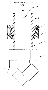
Fig. 1 is a schematic representation of the nozzle of the
invention,
Fig. 2 is a longitudinal, partly cross-sectional view of
the nozzle, and
3

CA 02131109 2001-11-07
Fig. 3 is plan view from the top of Fig. 2, of the
distributor assembly.
The nozzle as shown in Fig. 1 and 2 has a barrel
which is adapted to be connected to a source of
air-compressed foam for delivering a stream of the foam to
the distributor assembly 12. The assembly 12 has a
cylindrical section 13 and three tubular outlets 14, 16 and
18 which are angled at 45° relative to the vertical
direction (longitudinal axis 15 of the cylindrical section
13) and skewed by 120° against each other as best shown in
Fig. 3. One of the outlets 14 is truncated to enable, in
operation, a distribution of a stream of foam close to the
longitudinal axis of the section 13 while the other outlets
direct their respective foam streams in an annular zone
which is wider than the zone covered by the stream of the
outlet 14 (a greater delivery angle). As shown in Fig. 2,
the distributor assembly is coupled to the barrrel 1.0 by
means of a loose-fit bearing which consists of a coupling 20
which is threaded onto the barrel 10 and retained thereon by
means of a set screw :?1 and has a flange 22 which engages a
lip 24 on the cylindrical section 13 of the distributor
assembly 12 in a manner to enable a rotation of the
distributor assembly 1?. relative to the barrel 10.
As seen in Fig. 3, the tubular outlets 14, 16 and
18 have upper sections 24 which adjoin each other at: the
upstream end where they are attached to the cylindrical
section 13. The space between and around the points of
contact of the upper sections i.s filled, e.g. by brazing.
certain portions 26 of the cross-sectional areas of the
tubular outlets 14, :L6, 18 extend beyond the periphery of
the tubular section :L3 and may optionally be closed. This
is, however, not necessary as it does not impair the
operation of the nozzle if the portions 26 are left open.
4

~~3_L:1~9
In operation, a CAF foam stream is delivered through a
stationary piping system through the stationary barrel 10 and
through the three angled outlets. The skewed arrangement of
the outlets causes a turbine action of the distributor
assembly which is facilitated by the loose-fit bearing. The
force exerted by the foam exiting the nozzle causes the
distributor assembly to spin (clockwise in the arrangement of
Fig. 3). The three rotating streams form a solid cone which
distributes the foam uniformly over a broad area (typically
7m2 when the nozzle is located near the ceiling of a typical
room). Two of these distributors direct foam into the outer
area and the third is truncated to fill the inner area.
Because the foam stream is only redirected, the bubble
structure is not damaged and much of the forward momentum is
preserved.
It is the gentle redirection of the foam and its rotary
action which makes this nozzle unique. It has been tested as
part of a fixed piping fire suppression system in single and
2o multiple head configurations and proven effective on Class B
liquid fuel fires and Class A combustible fires.
The following is a list of the design limitations of the
nozzle:
A) The combined cross sectional areas of the outlets
should not be less than the cross sectional area of the foam
delivery tube nor should it be larger than 2 times the cross
sectional area of the delivery tube.
B) The number of foam outlets can be as few as 2 but
no greater than 4. A single outlet would still function,
however the vibration stresses from the imbalance are
undesirable. Outlet numbers greater than 4 can rob the
system of rotational power and can make the nozzle
5

~~.~:~~~9
unreliable. Two or three outlets provide reliable
operation and can produce a uniform coverage (3 outlets) to
protect floor areas or a wide hollow coverage (2 outlets) to
protect walls.
C) For the three-outlet nozzle the delivery angle of
two outlets is 45 degrees from vertical. The third outlet
delivers foam from 0 to 45 degrees. This produces a solid
90 degree cone of foam. Delivery angles significantly
greater than 45 degrees would function but the uniform
distribution would suffer. Delivery angles significantly
less than 45 degrees would rob rotational power and make the
nozzle unreliable. For these reasons a l0 degree tolerance
should be considered to be maximum.
D) For a 2 outlet nozzle any delivery angle from 45 to
90 degrees will function since the area of coverage is
intentionally hollow. A 90 degree angle, from vertical,
will deliver foam horizontally to cover the upper portion
of the surrounding walls. The foam will then flow under
gravity down the surface to protect the lower portion.
Delivery angles significantly less than 45 degrees would rob
rotational power and make the nozzle unreliable.
E) The foam outlet skew angle of 120 degrees on the
three-outlet nozzle can not be physically greater than 120
degrees and angles less than 110 degrees will reduce the
rotational power and affect the reliability of operation.
F) A 2 outlet nozzle can have a skew angle up to 180
degrees.
6

Representative Drawing
A single figure which represents the drawing illustrating the invention.
Administrative Status

2024-08-01:As part of the Next Generation Patents (NGP) transition, the Canadian Patents Database (CPD) now contains a more detailed Event History, which replicates the Event Log of our new back-office solution.

Please note that "Inactive:" events refers to events no longer in use in our new back-office solution.

For a clearer understanding of the status of the application/patent presented on this page, the site Disclaimer , as well as the definitions for Patent , Event History , Maintenance Fee  and Payment History  should be consulted.

Event History

Description Date
Inactive: Expired (new Act pat) 2014-08-30
Maintenance Request Received 2013-06-04
Inactive: Cover page published 2012-11-26
Inactive: Acknowledgment of s.8 Act correction 2012-11-20
Inactive: S.8 Act correction requested 2009-01-20
Inactive: Late MF processed 2008-10-22
Letter Sent 2008-09-02
Inactive: IPC from MCD 2006-03-11
Inactive: Late MF processed 2005-10-28
Letter Sent 2005-08-30
Grant by Issuance 2002-11-12
Inactive: Cover page published 2002-11-11
Pre-grant 2002-07-08
Inactive: Final fee received 2002-07-08
Notice of Allowance is Issued 2002-02-11
Letter Sent 2002-02-11
Notice of Allowance is Issued 2002-02-11
Inactive: Approved for allowance (AFA) 2002-01-22
Amendment Received - Voluntary Amendment 2002-01-15
Amendment Received - Voluntary Amendment 2001-11-07
Inactive: Office letter 2001-09-19
Revocation of Agent Requirements Determined Compliant 2001-09-19
Revocation of Agent Request 2001-07-30
Inactive: S.30(2) Rules - Examiner requisition 2001-07-23
Letter Sent 2000-10-11
Reinstatement Requirements Deemed Compliant for All Abandonment Reasons 2000-09-29
Deemed Abandoned - Failure to Respond to Maintenance Fee Notice 2000-08-30
Amendment Received - Voluntary Amendment 1999-12-10
Inactive: Correspondence - Prosecution 1999-09-21
Inactive: Status info is complete as of Log entry date 1999-08-31
Letter Sent 1999-08-31
Inactive: Application prosecuted on TS as of Log entry date 1999-08-31
Request for Examination Requirements Determined Compliant 1999-08-11
All Requirements for Examination Determined Compliant 1999-08-11
Letter Sent 1998-10-02
Reinstatement Requirements Deemed Compliant for All Abandonment Reasons 1998-09-24
Deemed Abandoned - Failure to Respond to Maintenance Fee Notice 1998-08-31
Application Published (Open to Public Inspection) 1996-03-01

Abandonment History

Abandonment Date Reason Reinstatement Date
2000-08-30
1998-08-31

Maintenance Fee

The last payment was received on 2002-07-25

Note : If the full payment has not been received on or before the date indicated, a further fee may be required which may be one of the following

  • the reinstatement fee;
  • the late payment fee; or
  • additional fee to reverse deemed expiry.

Patent fees are adjusted on the 1st of January every year. The amounts above are the current amounts if received by December 31 of the current year.
Please refer to the CIPO Patent Fees web page to see all current fee amounts.

Owners on Record

Note: Records showing the ownership history in alphabetical order.

Current Owners on Record
NATIONAL RESEARCH COUNCIL OF CANADA
Past Owners on Record
GEORGE P. CRAMPTON
Past Owners that do not appear in the "Owners on Record" listing will appear in other documentation within the application.
Documents

To view selected files, please enter reCAPTCHA code :


To view images, click a link in the Document Description column (Temporarily unavailable). To download the documents, select one or more checkboxes in the first column and then click the "Download Selected in PDF format (Zip Archive)" or the "Download Selected as Single PDF" button.

List of published and non-published patent-specific documents on the CPD .

If you have any difficulty accessing content, you can call the Client Service Centre at 1-866-997-1936 or send them an e-mail at CIPO Client Service Centre.

({010=All Documents, 020=As Filed, 030=As Open to Public Inspection, 040=At Issuance, 050=Examination, 060=Incoming Correspondence, 070=Miscellaneous, 080=Outgoing Correspondence, 090=Payment})


Document
Description 
Date
(yyyy-mm-dd) 
Number of pages   Size of Image (KB) 
Abstract 1996-02-29 1 14
Description 1996-02-29 6 241
Claims 1996-02-29 1 22
Drawings 1996-02-29 3 48
Claims 1999-12-09 1 31
Description 2001-11-06 6 237
Drawings 2001-11-06 3 33
Claims 2002-01-14 2 72
Representative drawing 2002-01-22 1 6
Representative drawing 1997-12-11 1 6
Courtesy - Abandonment Letter (Maintenance Fee) 1998-09-27 1 184
Notice of Reinstatement 1998-10-01 1 170
Acknowledgement of Request for Examination 1999-08-30 1 193
Courtesy - Abandonment Letter (Maintenance Fee) 2000-09-26 1 184
Notice of Reinstatement 2000-10-10 1 171
Commissioner's Notice - Application Found Allowable 2002-02-10 1 164
Maintenance Fee Notice 2005-10-24 1 173
Late Payment Acknowledgement 2005-11-06 1 166
Maintenance Fee Notice 2008-10-13 1 171
Late Payment Acknowledgement 2008-11-05 1 164
Fees 2003-08-26 1 24
Correspondence 2001-07-29 2 83
Correspondence 2002-07-07 2 71
Fees 1998-09-23 1 39
Fees 2000-09-28 1 29
Fees 2002-07-24 1 40
Correspondence 2001-09-18 1 19
Correspondence 2001-09-18 1 17
Fees 2001-08-23 1 31
Fees 1997-08-06 3 110
Fees 1999-06-29 1 30
Fees 1998-09-27 2 165
Fees 2004-08-15 1 24
Fees 2005-10-27 1 27
Fees 2006-08-20 1 23
Fees 2007-08-06 1 23
Correspondence 2008-10-21 1 30
Fees 2009-06-29 1 30
Fees 2010-07-14 1 30
Fees 2011-07-18 1 27
Fees 2012-06-25 1 30
Correspondence 2009-01-19 3 108
Fees 2013-06-03 1 29
Fees 1996-08-26 3 92