Note: Descriptions are shown in the official language in which they were submitted.
' 1311~ 1
WO 93/17145 . PCl`/US93/01784
'1 ITL~:
~ETHOD FOR PRODUCING A CAST ALUMINU~ VEHICLE WHEEL
BACKGROUND OF THE INVENTION
This invention relates in general to the manufacture
of cast aluminu~ products and, in particular, to an
improved method for producing a cast aluminum vehicle
wheel.
In producing cast aluminum alloy products, such as
vehicle wheels, it is generally necessary, after thè
initial casting operation, to subject the casting to a
series of metal treatment steps in order to produce a
casting having the desired tensile strength, yield
strength, elongation, and fatigue strength properties.
These steps include: (1) a "solution heat treatment" (SHT)
process and (2) an "aging~ (i.e., precipitation hardenin~)
process. In the SHT p~ocess, an aluminum alloy casting is
first heated to a "solution~ temperature of about 1000F
for a predetermined time such that certain soluble
constituents contained in the alloy (such as age hardening
constituent magnesium silicide Mg2Si) are dissolved into
"solid solu~ion". The casting is then immediately and
rapidly cooled (such as by quenching in a water bathj t~
retain the constituents in solid solution. This prevents
2~ rapid precipitation of the associated constituents which
would otherwise occur if the casting were allowed to slowly
cool through a certain temperature range. Next, during the
aging" process, the hardening constituents are
precipitated out of the solution in a controlled manner to
produce a casting having the desired mechanical properties.
The aging is effected either "naturally" at room
temperature over a period of at least 10-12 hours, or it
can be "accelerated~ by heating the casting to an elevated
temperature for a shorter period of time (e.g. 450 F for
30 minutes).
The conventional method of producing gravity-cast
aluminum wheels includes initially pouring a suitable
WO93/17145 PCT/US93/017~
.. :1 3 ~ 2
molten aluminum alloy, such as A356 aluminum, into a mold
through its gate channel until the molten alloy flows
upwardly through one or more mold risers. After the molten
alloy has completely solidified, the casting i5 removed
from the mold, at which time it can be degated (i.e., the
portion of the casting which solidified in the gate channel
is cut off) and quenched in water to cool the castinq to
room temperature. The casting is then derisered (i.e., the
riser portions of the casting are removed) and subjected to
~; fluoroscope inspection to locate any obvious casting
defects.
Next, a group of wheels (typically between about 70
and 350), are loaded onto racks and subjected to a "batch"
~ solution heat treatment process. The batch solution heat
treatment process is effected by placing the racks in a
;~ large gas-fired or electrical-resistance forced air
convection oven. In the convection oven, the castings are
heated to a desired ~solution" temperature (approximately
` ~ 1000F~ and are maintained at this temperature for
approximately 2 to 8 hours. Following heating, the batch
of wheels are immediately quenched in water to rapidly cool
the wheels. Following cooling, the wheels are machined-and
painted and/or clear coated, during which time they are
naturally aged at room temperature.
One of the problems associated with the above method
for producing cast aluminum wheels relates to the amount of
"work-in-process" which occurs as a result of the long
process times. It is known that once a casting is heated
to the correct "solution" temperature, proper solution heat
treatment will occur within about 5 minutes. However,
since a large number of wheels are heated during the batch
solution heat treatment process, it is difficult to
-~ maintain even and uniform temperatures in all the wheels.
Thus, to ensure that all the wheels are properly heat
treated, the time to solution heat treat the wheels is
usua~ly at least two hours.
W093/l7l45 1 3, ~ 9 :i PCT/US~3/Ul784
On a conservative estimate, the above described series
of metal treatment steps, beginning with the casting of the
wheel and through both the solution heat treatment and
aging processes, require at least 12 hours to produce the
wheels and more realisticly, takes closer to about 24
hours. Thus, any defect in the wheels (which- is typically
located during machining) is not readily discoverable until
a relatively large number of wheels are "in process". As a
result, a large number of wheels can be produced before a
casting defect is discovered. In addition, since the
wheels are cooled to room temperature prior to being
solution heat treated, additional energy (and time) is
needed to reheat the wheels up to the specific temperature
necessary for solution heat treatment. ~
~One alternate method for producing aluminum alloy
;~ ~castings, such as a piston, is disclosed in U.K. Patent No.
390,244. According to the method of this patent, an
`aluminum alloy material is cast in a mold and removed from
the mold while the temperature is above 662F t350C). The
casting is immediately placed in an oven maintained at a
specific elevated temperature in the range of 788 to 968F
(420 to 520C), and remains i~ the oven for a time period
between 10 and 30 minutes. Following heating, the castin~
is quenched in water, and then either naturally or
artificiallY aged~
Other methods for producing a cast article of aluminum
alloy material are disclosed in U.S. Patent Nos. 4,420,345
and 4,419,143, both issued to Ito et al. According to the
methods in these patents, an aluminum-silicon-magnesium
alloy or an aluminum-silicon-copper-magnesium alloy
containing 0.03 to 1.0% by weight of antimony is cast into
a mold. Then, after the casting has completely solidified
but before the temperature has fallen below 842F (450C),
the casting is placed in a heating furnace maintained at a
specific elevated temperature in the range of 896 to
, ~ ,
~ 1022F (480 to 550C), for a time period of less than 2
. - ,: , ,
W093/17l45 PCT/US93/0l7
~ 4
hours. Following heating, the casting is quenched in water
and then subjected to an artificial aging process at a
specific elevated temperature for less than 12 hours.
The methods disclosed in all of the above patents
S reduce the time to solution heat treat the cast aluminum
article by not allowing the casting to cool below a certain
temperature before initiating solution heat treatment.
However, they all still utilize forced air convection
furnaces to solution heat treat and/or artificially age the
castings. Some drawbacks of forced convection furnaces
~ include lenqthly heat-up time before reaching processing
; temperature, difficulty in obtaining uniform temperature
distribution, and sometimes inconsistent product quality.
Recently, electric infrared (IR) heating systems have
received increasing attention in certain industrial
~applications. In an infrared heating system, a product is
heated by generating electromagnetic radiation waves at a
specific frequency and intensity, and directing these waves
at the product. The particular frequency (i.e.,
wavelength) and intensity are selected in accordance with
the particular heating requirements of the product. While
infrared heating systems are used in a variety of different
industrial applications, they are primarily used to dry
and/or cure products with layers or thin films on their
surfaces.
SUMMARY OF THE INVENTION
This invention relates to an improved method for
producing a cast aluminum vehicle wheel wherein, instead of
using a forced convection furnace to heat treat the wheel,
an infrared heating system is used to either solution heat
treat or artificially age the wheel or both. After the
initial casting operation, the wheel is maintained in the
mold until its temperature has fallen sufficiently to
prevent "center pull" deformation when the wheel is removed
from the mold ~to about 800F). Thereafter, the wheel is
. . .
. . .
.
WO93/17145 213, l~3l~ PCT/US93/01784
removed from the mold and preferablv degated, and solution
heat treatment of the wheel is preferably initiated before
the wheel temperature has fallen to a point wherein
significant precipitation of hardening constituents from
the "solution" occurs. This temperature is preferably
above about 700F (371C). Generally, the time between
removal from the mold and the commencement of the solution
heat treatment process is less than about 2 minutes.
A first infrared heating system is used to effect
~' solution heat treatment of the wheel. The first infrared
heating system rapidly heats the wheel to a temperature in
a solution heat treatment range of 980 to 1025F (526 to
552C) and maintains that temperature for a period of 2 to
l0 minutes to dissolve the age hardening constituents.
Preferably, the wheel is indexed through an infrared
heating system having a series of separate heating stations
for individually heating each wheel.
' Each infrared heating station includes means for
monitoring the actual temperature of the wheel, and the
heating of the wheel at eàch station is controlled in
accordance with its monitored temperature. One method of
- 'control'includes monitoring the wheel temperature during
the initial rapid heating. The heat energy supplied to the
wheel is reduced when the wheel temperature reacXes a
predetermined temperature in the solution heat treatment
temperature range. An alternate control method includes
measuring an initial wheel temperature. 8ased upon the
initial wheel temperature, an initial rapid heating period
is determined. When the initial heating period ends, the
~he heat energy supplied to the wheel is reduced. Also,
for future reference, the heating temperatures and times
for each wheel can be recorded.
~'; Immediately after the heating operation, the wheel is
quenched'in water to ensure that substantially all the age
hardening constituents are retained in "solid~ solution.
' ~; After this quenching operation, a second infrared heating
W O 93/17145 P ~ /US93/01784
~ i 3 `~
system is used to effect accelerated artificial aging of
the wheel. The second infrared heating system heats the
wheel to a temperature in the range of ~00 to ~00F (204~
to 260C) for a period of 2 to 10 minutes. Preferably, the
second infrared heating system is integrated with the first
infrared heating system and includes separate heating
stations for individually heating each wheel immediately
after the wheel has been quenched. Following aging, the
wheel is derisered, machined, and coated.
~ 10 This method improves the manufacturîng efficiency
-~ normally associated with producing cast wheels and enables
a finished wheel to be completed in approximately 30 to 60
minutes after the initial casting operation. Thus, the
amount of "work-in-process" is substantially reduced,
5 ~ ~ Other advantages of this invention will become
apparent to those skilled in the ar~ from the following
;detailed description of the preferred embodiment, when read
in light of the accompanying drawings.
: 20 BRIEF DESCRIPTION OF THE DRAWINGS
Fig. 1 is an elevational view of an aluminum alloy
wheel casting (shown with its outboard side facing
downwardly) which is produced in accordance with this
invention.
Fig. 2 is a block diagram showing the steps of the
method of this invention.
Fig. 3 is a graph illustrating the time-temperature
parameters preferably followed by the method of this
invention.
Fig. 4 is a top plan view of an infrared heating
system used in producing a cast aluminum wheel according to
the method of this invention.
Fig. 5 is a partial cross sectional view taken along
~:
the line 5-5 of FTG. 4 and showing one of the individual
infrared heating stations.
~,
W O 93/17145 2 ~ 3 ~ 1 9 ~ P ~ /US93/01784
Fig. 6 is a schematic view of an alternate embodiment
of an infrared heating system which can be used in
producing a cast aluminum wheel according to the invention.
Fig. 7 is a schematic view of a further alternate
embodiment of an infrared heating system.
Fig. 8 is a flow chart for a closed loop control
method for the heating system used in producing a cast
aluminum wheel according to the invention.
Fig. 9 is a temperature/time graph for the control
method shown in Fig. 8.
Fig. l0 is a flow chart for an alternate embodiment of
the control method shown in Fig. 8.
Fig. ll is a flow chart for another embodiment of the
control method shown in Fig. 8.
~-~ 15 Fig. 12 is a flow chart for an open loop control
method for the heating system used in producing a cast
aluminum wheel according to the invention.
Fig. 13 is a temperatureltime graph for the control
method shown in Fig. 12.
Fig. i4 is a graph illustrating the functional
relationship betwèen the initial wheel heating time and the
wheel temperature for the control method shown in Fig. 12.
Fig. l5 is a flow chart for an alternate embodiment of
the control method shown in Fig. 14.
Fig. 16 ia a graph illustrating the functional
relationship between the initial wheel heating time and the
wheel temperature and weight for the control method shown
in Fig. l2.
~ .
DETAILED DESCRIPTION OF THE PREFERRED EMBODIMENT
Referring now to the drawings, there is illustrated in
Fig. l an elevational view of a typical gravity cast
- aluminum alloy vehicle wheel, indicated generally at l0,
which can be produced in accordance with the method of this
invention. When gravity cast, molten aluminum is poured
into the associated mold (not shown) through a channel to
,..
;`~
WO93/1~145 PCT/US93/01784
1~i311'i I 8
form a gate 12 and, as the molding cavit~ is filled, the
molten aluminum flows upwardly into a center riser 13 and a
rim lor side) riser 14. lt will be appreciated that, while
the invention is illustrated and described herein in
conjunction with a wheel formed by the gravity castinq
method, the invention can be used with other casting
methods such as, for example, low pressure, squeeze, pore
free, semi-solid and die casting. With these other
methods, the wheel would be cast without a gate l2 or
risers 13 and 14.
Also, while the drawings and description herein show
;~ producing a cast "one piece" wheel l0, the invention can be
practiced to form only a cast component of a multi-piece
wheel such as, for example, a center spider portion (not
shown), which is then secured to a separately formed rim
(not shown) in a known manner to form the finished wheel.
The cast component can also be the full front face of the
wheel which is subsequently secured to a formed partial
rim. As used in this description and the following claims,
the term "wheel" includes not only a one piece cast wheel,
but also a cast component of a multi-piece wheel.
The wheel l0 can be cast from a suitable aluminum
- casting alloy material such as, for` example, A356 aluminum.
This type of aluminum generally includes approximately, by
weigh~, 6.0 to 7.5% silicon, 0.25 to 0.45~ magnesium, about
0.20% iron, about 0.20% titanium, 0.008 to 0.04~ strontium,
and the balance aluminum. The term balance aluminum is
intended to to include residual amounts of other elements
which may be present in the alloy material, such as
manganese, copper, calcium, antimony, zinc, barium, carbon,
zirconium, and sodium. The strontium is used as a casting
modifier to lower the required solution heating time.
Other suitable casting alloys include A333 or A357
aluminum, or magnesium.
Turning now to Figs. 2 and 3, the particular method of
this invention will now be discussed. Initially, in step
,~; ' .
~ ~ .
W093/1714S ~ 1~ 3 1~[1 PCT/~S93/017~4
20, molten aluminum alloy at a temperature T~ (about 1300
F) is poured into a gravity type mold (not shown) at time
to to IOrm a casting having roughly th~ desired final shape
of the wheel lO. The wheel lO remains in the mold until
its temperature has fallen sufficiently to prevent any
~center pull~ wheel deformation when the wheel lO is
removed from the mold (shown in FIG. 3 as temperature T2 at
time tl), and is then immediately subjected to a solution
heat treat process prior to its temperature falling to a
0 point where significant precipitation of the hardening
constituents has occurred (shown as temperature T3 at time
t2). ~Center pull" deformation occurs when the temperature
of the wheel has not cooled sufficiently to allow the wheel
to be pulled fro~ the mold without deformir.g its shape.
While the particular temperature may vary depending on the
particular construction of the casting, it has been found
~ that, in most instances, the temperature T2 of a typical
I wheel lO formed from A356 aluminum must fall below about
~-- 800F to prevent "center pull" deformation. In step 22, when the wheel lO is removed from the mold, the gate 12 and
the risers 13 and 14, shown in Fig. l, remàin as part of
the casting.
After the wheel lO has been removed from the mold, it
is preferable to degate the wheel lO, in step 2-~, and then-
initiate an SHT process, in step 26, as soon as possiblethereafter and prior to significant precipitation of the
age hardening constituents (e.g., Mg2Si~ in the hot
casting. However, as will be discussed below, the solution
heat treatment of the wheel lO can be initiated with the
gate 12 remaining on the wheel lO, and the gate can be
later removed. Depending upon the particular percentages
¦~ of magnesium and silicon in the wheel lO, it is preferable
that the temperature T3 at time t2 be no less than about
~; 700F (371C) before SHT is initiated; however, in some
- ~ 35 instances, the temperature T3 can fall to about 400 F and
still obtain satisfactory results. Normally, in order to
.~ ~ ~
1~
W093/17145 PCT/US93/01784
: :', `, i `.j l 10
maintain the desired temperature of the casting, the time
between removal from the mold in step 22 (at time tl) and
the initiation of the SHT process in step 26 (at time t2)
is less than about 2 minutes.
In accordance with one feature of this invention, in
step 26, an infrared heating system is used to effect
individual solution heat treatment of the wheel l0. In
'' step 26, the infrared heating system initially rapidly
heats the wheel l0 up to a desired solution temperat~re T4
within a time interval t2 to t3. Generally, the
' temperature T4 is in the range of 980 to 1025F (527 to
552C)! and the time interval t2 to t3 is approximately l -
~' 4 minutes, depending on the initial temperature of wheel
` and the infrared heating rate. Once the wheel l0 reaches
the desired temperature T4, the infrared heatinq system
maintains the wheel l0 at the temperature T4 for a time
interval t3 to t4, which is about 2 - l0 minutes.
Preferably, for a wheel formed from A356 aluminum, the
température T4 is approximately 1000F (538C), the time t2
to t3 is about l - 2 minutes, and the time interval t3 to
t4 is approximately 3 - 4 minutes. Thus,, the total time
~ interval t2 to t4 is about 5 minutes.
`~, , After completion of the solution heat treatment in
step 26, the wheel l0 is immediately transferred to a water
bath in step 2~ within a time interval t4 to tS.
Preferably, the time between completion of solution heat
treatment in step 26 and commencement of quenching in step
28, is less than l0 seconds. In step 2B, the wheel l0 is
;~ quenched in the water bath, and is then transferred to an
accelerated artificial aging process in step 30, within a
time interval t5 to t6. Preferably, the time interval t5
to t6 is around 45 seconds such that the total time
, ;~ interval t4 to t6, which represents the time between
~,completion of solution heat treatment a~d commencement of
~artificially aging, is approximately l minute. The water
5~
- ~ ~`
,':
, ' :
WO 93/17145 h ~ 9 1 PCT/US93/017
11 - .
bath is preferably maintained at a temperature in the range
of 120 to 220F (48 to 104C).
In accordance with yet another feature of this
invention, after the wheel 10 has been quenched in the
water bath in step 28, an infrared heating system, in step
30, is used to effect the accelerated artificial aging
process. Preferably, this occurs immediately after the
quenching of step 28. In step 30, the infrared heating
system initially heats the wheel 10 up to a desired aging
temperature T5 in a time interval t~ to t7, and then
maintains the wheel 10 at the temperature T5 for a time
^ interval t7 to t8. The temperature T5 is in the range of
400 to 500F (204 to 260C), the time interval t6 to t7
is approximately 1-4 minutes, and the time interval t7 to
*8 is appro~imately 2-10 minutes. Preferably, the
temperature ~5 is about 450 F, the time interval t~ to t7
~ is 1_2 minutes, and the time interval t7 to t8 is about 3-4
`~ minutes, such that the total time interval ~6 to t8 is
around 5 minutes.
Immediately following the artificial aging process in
~; step 30, the wheel 10, in step 32, is quenched in a water
bath to cool the wheel for normal handling. After
quenching, the wheel can be subjected to fluoroscope
inspection, in step 34, to determine if the wheel lO has
any obvious casting defects. Following fluoroscope
inspection, if the wheel 10 has not been dega~ed in step 24
prior to being solution heat treated in step 26, the wheel
10 is degated in step 36 to remove the gate 12 from the
casting. In step 38, the risers 13 and 14 are removed from
l 30 the wheel 10. Following step 38, the wheel 10 is machined
¦ as necessary into its final desired shape. Finally, in
¦~ step 42, the wheel 10 is clear coated (and/or painted if so
desired), to produce the finished cast aluminum wheel.
In the preferred embodiment, the po~tion of the
3~ process beginning with the removal of the wheel 10 from the
mold in step 22 at time tl and through the accelerated
, ~
,.~ ~
WO g3/17145 , PCl`/USg3/01784
:,'
~13~ 1 ',1 1
artificial aging of the wheel 10 and quenching in s~ep 32
at time t8, can be completed in less than 30 minutes and
preferably, in less than 15 minutes. Since generally the
time between step 30 and the machining in step 40 is less
than about 30 minutes, a completed wheel, ready for
coating, can be produced in less than 45 minutes. Thus,
the use of infrared heating systems to effect both solution
heat treat and artificial aging greatly reduced the process
time as compared to the prior art methods. As a result,
~; 10 any defects in a wheel can be discovered before a large
quantity of wheels have been produced. Further, the use of
the infrared heating systems have been found to produce
more uniform and consistent mechanical properties in the
wheels.
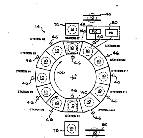
Turning now to Fig. 4, there is shown an exa~ple of an
~- integrated infrared heating system, indicated generally at
44, which can be used to both solution heat treat and
artificially age the cast aluminum alloy wheel 10. As
shown therein, the infrared heat system 44 is an indexing
type carousel arrangement and includes stations #l through
. .
#12 for processing the wheel 10. The system 44 includes an
- indexing unit (not shown) for individually advanclng wheels
through the system at a predetermined rate. As will be
discussed, stations #2 through #6 are operative to effect
solution heat treat of the wheel 10, while stations #8
through #12 are operative to effect accelerated artificial
aging of the wheel 10.
Initially, an individual wheel 10 is loaded onto the
indexing unit at station #1. The indexing unit rotates
about an axis A and maintains a single wheel at each
station for approximately S5-60 seconds, with an indexing
~ time from one station to the next of less than three
-~ seconds. Accordingly, the total time required to index a
-;~ wheel through *he integrated infrared heating system 44 in
order to both solution heat treat and artificially age the
wheel, is less than 13 minutes.
' ~:
WO93/17145 PCT/US93/01784
~.'1.3-1. !.q-l
13
Each of the stations #l through #6 and #8 through #12
is provided with a separate means for sensing the actual
temperature of the wheel at the respective station, such as
temperature sensors 46. It has been found preferable to
use one or more optical pyrometers at each station as the
means for detecting the actual wheel temperature. Each
temperature sensor 46 generates à signal representative of
the temperature of the wheel l~ at the respective station.
The temperature sensors are connected to a control unit 48
which, as will be discussed, functions to separately
control the heating of the wheel at each heating station.
In FIG. 4, stations #2-#6 and #8-#12 are heating stations
and are provided with high intensity heating ovens similar
~ to that shown in FIG. 5.
The control unit 48 is operative to control the
heating at each individual station by generating controlled
~ power signals on lines 50 to a plurality of infrared
I ~ emitters 52 (shown in FIG. 5). As will be described below,
the power signals on the lines 50 are controlled in
~; 20 response to the monitored temperature of the respective
` wheel, and the desired heating phase of the process. In
~ :~
addition, the control unit 48 generates a signal to a
recorder (REC) 5l. The recorder 51 is operative to
maintain an individual record of the heating temperatures
and times of each wheel as the wheel is indexed through the
system 44. Thus, if a wheel (which is later machined and
coded with an identifying number) is found to be defective
as a result of the heat treating process, the recorder 51
can be used to identify the specific time/temperature
profile for that wheel and then identify any other wheels
heated with similar profiles. As a result, the recorder 51
can quickly identify those wheels which were heated at the
same temperatures as the defective wheel, and only the
identified wheels need initially be checked for possible
~ 35 defects.
,~
,`"'~
W093/17~4S PCT/~S93/017X4
ii 14
As previously mentioned, the solution heat treat
process is commenced as quickly as possible after the
casting operation, and preferably the wheel lO is indexed
to station #2 before its temperature has fallen below
700F. At this point, a high intensity electric infrared
heating oven 54, which is best shown in Fig. 5, is actuated
to begin to heat the wheel lO up to the temperature
' necessary to èffect solution heat treatment. The high
~ intensity electric infrared heating oven 54 includes a
`~ generally rectangular shaped enclosure 56 having an upper
wall 58, a lower wall 60, and two side walls 62. The lower
wall 60 is provided with an opening 64 formed therein.
The plurality of high intensity electric infrared
emitters 52 are disposed within the enclosure 56 for
qenerating infrared radiation in order to heat the wheel lO
, in the desired manner. The emitters 52 are located near
;~ ' the upper wall 58, each of the side walls 62, and the lower
wall 60 of the oven 54 on opposite sides of the opening 64.
~' In the preferred embodiment, the high intensity electric
, 20 infrared emîtters 52 can be tungsten filament quartz lamps
,~ ` with lO0 watt per inch power density. If necessary the
- ~ emitters 52 can be grouped into a plurality of individual
zones, and the,heating of each zone can be separately
controlled.
As shown in Fig. 5, the interior of the enclosure S6
is lined with insulation 66 to minimize the heat loss and
' increase the heating efficiency of each oven 54. A
passageway 68 is provided in each enclosure 56 through
'~ which the wheel lO is indexed. Also, appropriate duct~ork
70 is provided in each enclosure 56 to supply cooling air
to the emitters 52 to prevent them from overheating.
The indexing unit includes a plurality of spindle
~ assemblies, one located at each station, and which are
", rotatab,~e about an axis B and which extend upwardly through
~ 35 the opening 64 of the lower wall 60. The spindle assembly
',' ; 72 includes a vertical shaft 74 having a bracket 76
^'::~
,
WO g3/17145 2 1 3 1 1 ~ PCT/US93/017X4
1 5
releasably secured thereto for supporting the wheel 10.
The bracket 76 is specially designed to support the
particular wheel configuration. The spindle assembly 7~ is
coupled to a power rotating assembly (not shown) for
rotating the wheel 10 ~preferably at a speed of about 3 - 5
r.p.m.) about the axis B of the spindle assembly 72 as the
wheel is being subject to infrared radiation at the
respective heating station.
- At station #2, the infrared emitters 52 begin to
rapidly heat the wheel 10 at a rate of about 100 to 200F
(43 to 93C) per minute. Normally, due to the initial
temperature of the wheel when heating begins, and the
indexing cycle of the system, the wheel will not reach the
desired solution temperature at station #2. Thus, when the
~;~ ; 15 wheel 10 is indexed to station #3, it is heated at about
; the same rate until the temperature of the wheel 10 reaches
: ^ :
`~ ~ the desired solution temperature in the range of 980 to
1025F (527 to 552C). Thereafter, the heat energy
supplied by the infrared emitters 52 is reduced to maintain
20~ the temperature of the wheel at the desired solution
temperature (through stations #4-#6) until the end of the
solution heat treat cycle.
Next, after the wheel 10 is indexed from station #6 to
station #7, it is lifted from its associated spindle
assembly 72, and is immediately quenched in a water tank
74. Immediately thereafter, the wheel 10 is returned to
its spindle assembly 72 and is indexed to station #8 to
begin an accelerated artificial aging process.
Alternatively, the wheel 10 can be cooled to room
temperature after is has been quenched at station #7 and
- then unloaded onto a conveyor 76 and then derisered,
machined, painted, and naturally aged in the conventional
manner.
, ~
-~ At station #8, the control unit 48, in response to the
,,~ - ~ ~
monitored temperature of the wheel, generates power signals
; to the associated emitters to begin to heat the wheel at a
.~ ,,, , ~
WO93/17145 PCT/US93/017
~ 16
predetermined rate (preferably at 100-200 F per minute) up
to the desired aging temperature which, as previously
mentioned, is preferably in the range of 400 to 500F
(204 to 260C). Normally, due to the initial temperature
of the wheel when heating begins, and the indexing cycle of
the system, the wheel will not reach the desired aging
temperature at station #8. Thus, once the wheel 10 is
indexed to station #9, it continues to be heated at about
the same rate until the desired aging temperature is
reached. Thereafter, the control 48 accurately maintains
, the wheel at the desired aging temperature through stations
- ~10-#12 until the completion of the aging process.
Finally, the wheel 10 is indexed from station #12 to
station #l and where it is lifted from the station and is
quenched in a water tank 78 to cool the wheel for further
handling. The wheel 10 is then placed on a conveyor 80
-~ which transfers the wheel to a location wherein the
additional operations of steps 34 - 42 can be performed.
` ~ Fig. 6 illustrates a schematic view of a further
example of a high intensity electric infrared heating
system 90 which is similar to the high intensity electric
infrared heating system 44 shown in Fig. 4, except that it
is not an integrated heating system. As shown therein, the
25 wheel 10 can be loaded at station #1 and indexed through
heating stations #2 through $6 to effect either a solution
heat treatment process or an accelerated artificial aging
process of the wheel 10.
Fig. 7 illustrates a schematic view of yet a further
example of a high intensity electric infrared heating
system 92 which is similar to the high intensity electric
infrared heating system 44 shown in Fig. 5, except that it
is not configured in a carousel arrangement. As shown
therein, the wheel 10 can be loaded at station #1 and moved
through heating stations #2 through #6, which are arranged
in straightline type configuration, to effect either a
.
'~
WO 93/17145 . 2 1 3 1 1 q~3 1 PCI`/US93/017X4
solution heat treatment process or an accelerated
artificial aging process of the wheel 10.
Several control methods are available to control the
amount and application rate of heat energy applied to each
wheel during the above described heat treating processes.
One such control method consists of monitoring the wheel
temperature, Tw, as a predetermined level of heat energy is
applied to the wheel l0 to rapidly increase the temperature
thereof. When TW reaches a predetermined temperature
included within a predetermined temperature range, the
, amount of heat energy applied to the wheel 10 is reduced to
` maintain the wheel l0 within the predetermined temperature
ranqe. Because the actual temperature of the wheel is used
to control the level of heat energy applied to the wheel,
the control method constitutes a form of closed loop
feedback control.
The above described closed loop control method is
illustrated by the flow chart shown in Fig. 8 and the
temperature/time diagram shown in Fig. 9.. Fig. 9
corresponds to the solution heat treatment portion of the
graph æhown in Fig. 3. For descriptive purposes, the
- control method is described in the following by referring
to the infared heating system 44 shown in Fi~. 4; however,
the control method can be used with other heating-systems.
As described above, the wheel 10 is loaded onto the
indexing carousel at station #l and indexed into heating
; station #2. Then, as shown in functional block 100 in Fig.
8, the control unit 48 causes the heating system 44 to
provide an initial predetermined level of heat energv to
the wheel 10, causing a rapid wheel temperature rise. This
is accomplished by applying a voltage to the infared
emitters 52 contained in station #2, beginning at time to~
Typically, the maximum allowable voltage is applied to the
emitters 52 to provide a maximum level of heat energy to
the wheel 10.
, ~
,,~
,'
WO93/1714S PCT/US93/017~
r 1 i 3 1 i Ji l8
The rapid temperature rise occurs during an initial
heating time period, tINT, as shown by a heating ramp
portion lOl of the temperature/time diagram in Fig. 9. As
the wheel lO is heated, TW is monitored by the temperature
sensors 46, as shown in functional block 102 in Fig. 8. In
the preferred embodiment of the control method, the
temperature monitoring is continuous, however, the control
method also can include monitoring by sensing TW at a
plurality of times separated by predetermined time
intervals.
W is supplied to the control unit 48 and, in decision
block 103, compared to a predetermined solution heat
treatment ( SHT ) temperature, TSHT . TSHT
a particular value is stored in the control unit 48. The
pa~rticular value used for TSHT is contained within a
predetermined SHT temperature range. The SHT temperature
range is shown as the horizontal shaded area in Fig. 9 and
is bounded by a lower temperature value, TL, and an upper
temperature value, Tu. The particular SHT temperature
range is typically narrow and a function of the particular
aluminum alloy used to cast the wheel lO. As described
above, a SHT temperature range for the aluminum alloy A356
- from 980F (526C) to 1025F (552C) has been successfully
~ used.
- 25 As long as TW is less than TSHT~ the wheel lO
continues to be heated at the initial predetermined level
of heat energy provided by the infared em~itters 52.
Depending upon the particular wheel, it may be necessary to
- index the wheel through more than one of the heating system
stations before TW reaches TSHT.
When TW reaches TsHT, the control unit 48 causes the
voltage applied to the infared emitters 52 to be lowered.
This reduces the heat energy provided by the emitters 52 to
a lower predetermined level, as shown in functional block
- 104 in Fig. 8. Depending upon the tolerances of the
- sensors 46 and the control unit 48, TW may slightly exceed
W O 93/17145 , ~ 9 '3 PC~r/US93/01784
19
TsHT before the e~itter voltage is reduced. After the
emitter voltage is lowered, Tw typically follows a
transient, as shown at 105 in Fig. 9, during which T~l
continues to increase for a short time period and then
decreases to a temperature within the SHT temperature
range. It is to be appreciated that TW may exceed TU for a
short period of time during the transient. The reduced
heat energy level provided by the emitters 52 maintains TW
at this temperature, as shown by a generally horizontal
portion 106 of the temperature/time diagram in Fig. 9.
As illustrated in ~ig. 9~ TW is maintained within the
i predetermined SHT temperature range for a predetermined
~ solution heat treatment time period, tSHT, extending from
- the end of tINT to a treatment end time, tEND. The time
period tSHT can be determined from an empirical formula or
from actual solution heat treatment experience. During
tSBT, the wheel 10 continues to be indexed through the
heating system 44. As shown in decision block 107, the
control unit 48 monitors the t-ime that the wheel 10 is
exposed to the lowered heating level. Once tEND is
reached, the control unit 48 ends the solution heat
treatment cycle by deenergizing the infared emitters 52
which are supplying heat to the wheel 10. The production
of the wheel 10 then continues as described above.
A second embodiment of the above described closed loop
control method is illustrated by the flow chart shown in
Fig. 10. This embodiment includes compa~ing the wheel
temperature, Tw, to a predetermined maximum temperature'
30 TMAX, at a time occurring subsequent to the reduction of
the heat energy. The temperature comparison functions to
preclude overheating the wheel 10 if the heating system 44
has malfunctioned. The value of TMAX is selected to be
~;~ greater than TU and is illustrated in Fig. 9 by the upper
;~ ~ 35 dashed horizontal line. Typically, TMA is S to 10F above
~;~ T .
s~
,,'~ ::
,.
W O 93~17145 PC~r/US93/01784
~ ~ 3 1 i ~ 1 20
As shown in functional block 110 in Fig. 10, the
initial temperature To of the wheel 10 is measured at to.
This may be done at either station #1 or #2 of the heating
system 44. Because the initial predetermined heating rate,
rINT~ f the heating system 44 and TMAX are known, an
estimated time period needed for the wheel 10 to reach
TMAX, t, can be calculated as:
t=(TMAx-To)`/rINT
A temperature check time tCK, at which TW is compared
to TNAX, is then calculated as
tCK O
The temperature check time corresponds to the time at
which TW will reach TMAX if the control unit 48 does not
reduce the voltage applied to the infared emitters 52 when
required. This potential maIfunction of the control unit
48 would allow the rapid heating of the wheel 10 to
continue, as illustrated by a dashed extension 108 of the
heating ramp 101 in Fig. 9 to TMAX.
The steps shown in flowchart blocks 111 through 114 in
Fig. 10 are the same as the steps shown in blocks 100 and
102 through 104 in Fig. 8. However, in functional block
115 in Fig. 10, TW is measured at tCK, as TW(tcR). In
decision block 116, TW(tCK) is compared to TMAX. If
TW(tCK) is equal to or greater than TMAX, the control unit
48 determines that the heating system 44 has malfunctioned.
Accordingly, the con~rol se~uence branches to functional
block 117 to further reduce the heat energy supplied by the
infared heaters 52 before the the wheel 10 melts. As an
alternate, the heating system 44 can be totally shut down
in functional block 117. Then in functional block 118, an
alarm is signaled to alert the operators of the problem.
If Tw(tcK) is less than TMAX~ the control method proceeds
as described above to maintain the wheel 10 within the
predetermined temperature range until tEND is reached. At
tEND, decision block 119 causes a branching of the control
method to end the heating cycle.
W O 93/17145 ~' 1 3 1 1 ~3 '~ P ~ /US93/01784
A third embodiment of the closed loop control method
is illustrated by the flow chart shown in Fig. 11. The
control method is similar to that shown in Fig. 10, except
that TW is monitored during the time period between tCK to
tEND to assure that TMAX is not exceeded. Thus, in Fig.
11, functional block 115' indicates that TW is monitored
beginning at tCK. In decision block 116', if TW exceeds
TMAX between tCK and tEND~ the control unit 48 branches to
functional block 117 to further reduce the heat energy
supplied to the wheel 10. As an alternate, the heating
system 44 can be totally shut down in functional block 117.
This protects the wheel 10 from being overheated if the
control unit 48 does not sufficiently reduce the voltage to
the emitters 52 when required. TW can be monitored
continuously, at a plurality of times separated by
predetermined time intervals, or at a single predetermined
time.
An alternate control method to control the heating of
the wheel 10 consists of calculating an initial time period
for rapid heating of the wheel 10. This initial heating
time period is a function of the initial wheel temperature.
The initial predetermined level of he~t energy is applied
to the wheel lO for the initial heating time period, after
which the amount of heat energy is reduced. Because the
actual wheel temperature is not monitored during the
initial heating time period, there is no feedback involved
in the control method. Therefore, the alternate control
method constitutes a form of open loop control.
The above described open loop control method is
illustrated by the flow chart shown in Fig. 12 and the
temperature/time diagram shown in Fig. 13. Fig. 1~
corresponds to the solution heat treatment portion of the
graph shown in Fig. 3. For descriptive purposes, the
control method is again described by referring to the
heating system 44 shown in Fig. 4; however, the control
method can be used with other heating systems.
A~
WO93/171~5 PCT/US93/01784
~ 22
As described above, the wheel l0 is loaded onto the
indexing carousel at station $ l. As shown in functional
block 120 in Fig. 12, at to~ the wheel temperature To is
measured by a temperature sensor 46 and supplied to the
control unit 48. An initial wheel heating time period tINT
for rapidly heating the wheel l0 to a predetermined
temperature, TSHT, is then calculated by the control unit
48. The time period tINT is a function of To~ The
functional relationship between tINT and To is illustrated
-~ in Fig. 14 as a time/temperature curve which can be stored
in the memory of the control unit 48. As in the closed
- loop method described above, TsHT is within the SHT
temperature range. The SHT temperature range is shown as a
horizontal shaded area in Fig. 13 and is bounded by a lower
temperature value, TL, and an upper temperature value, Tu.
Once tINT is calculated, a termination time, tl, for
ending the initial rapid heating of the wheel l0 can be
determined (in functional block 120). Based upon the
~;; 20 desired ~olution heat treatment time period, tSHT, a
-~ termination time, t2, or ending the solùtion heat
treatment can also be calculated. The time period tSHT can
be determined from an empirical formula or from actual
.
solution heat treatment experience. During tSHT, the wheel
l0 continues to be indexed through the heating system 44.
Upon completion of the calculations indicated in functional
block 120, the wheel l0 is indexed into station #2.
In functional block 121, the control unit 48 causes
the heating system 44 to provide an initial predetermined
level of heat energy to the wheel l0, causing a rapid wheel
temperature rise. This is accomplished by applying a
voltage to the infared emitters 52 contained in station #2,
beginning at time to. Typically, the maximum allowable
voltage is applied to the emitters 52 to provide a maximum
level of heat energy to the wheel l0. This continues until
tl is reached, as determined in decision block 123. The
rapid temperature rise is shown by a heating ramp portion
W O 93/17145 2 ~ 3 ~ PC~r/US93/01784
122 of the time/temperature diagram between the times to
and t1 in Fig. 13.
When t1 is reached, the control unit 48 causes the
voltage applied to the infared emitters 52 to be lowered.
This reduces the heat energy provided by the emitters 52 to
a lower predetermined level, as shown in function block
124. The lower heating level maintains TW within the
predetermined SHT temperature range, as shown by a
generally horizontal portion 125 of the time/temperature
diagram in Fig. 13. It is to be appreciated that TW may
exceed TU for a short transient period following the
voltage reduction.
Once the heating level has been reduced, the control
unit 48 monitors the time that the wheel 10 is exposed to
the lowered heating level, as shown in decision block 126.
Upon~reaching the heat treatment termination time t2, the
control unit 48 ends the heating cycle by deenergizing the
infared heaters 52 which are supplying heat to the wheel
10. The production of the wheel 10 then continues as
described above.
A second embodiment of the open loop control method is
illustrated by the flow chart in shown in Fig. 15. The
second embodiment includes comparing the wheel temperature,
Tw, to a maximum temperature, TMAX, after the rapid heating
period to preclude overheating the wheei 10. As in the
closed loop control method described above, TMAX is
selected to be greater than TU and is illustrated in Fig.
13 by the upper dashed horizontal line. Typically, TMAX is
5 to 10F above Tu.
The initial portion of the control method shown in
flow chart blocks 130 through 133 in Fig. 15 is the same as
shown in blocks 120, 121, 123 and 124 of Fig. 12. Once t
is reached and the heating level has been reduced in
functional block 133, Tw is monitored by temperature
sensors 46 in functional block 134 and compared to the
maximum temperature TMAX in decision block 135.
~"~
W093/17145 PCT/US93/n1784
~1`3 1 24
If TW i5 equal to or greater than TMAX, the control
unit 48 determines that the heating system 44 has
malfunctioned. Accordingly, the control sequence branches
to functional block 136 to further reduce the heat energy
supplied by the infared heaters 52 before the the wheel 10
melts. As an alternate, the heating system 44 can be
totally shut down in functional block 136. Then in
functional block 137, an alarm is signaled to alert the
operators of the problem.
If TW is less than TMAX in decision block 135, the
control method proceeds as described above to maintain the
emitters 52 at the reduced energy level until t2 is
reached, at which time decision block 138 causes a
branching of the control method to end the heating cycle.
TW can be monitored continuously, at a plurality of times
separated by predetermined time intervals, or at a single
predetermined time.
A third embodiment of the open loop control method
includes determining tINT as a ~unction of both the initial
wheel temperature and the wheel weight, Ww. A first scale
140 for weighing the wheel 10 is shown in phantom at
~ station #l in Fig. 4; however, the scale could be located
¦ - at station #2 or entirely separate from the heating system
44.
The functional relationship between tINT and To and Ww
is illustrated in Fig. 16 as a family of time/weight curves
which can be stored in the memory of the control unit 48.
Each time/weight curve corresponds to a particular To~
shown as Tol, To2, and To3, and provides tINT as a function
of Ww. In Fig- 16, To1 is greater than To2 and To2 is
greater than To3. The three time/weight lines shown in
Fig. 16 are meant to be illustrative, more or less
time/weight lines can be used in a particular application.
In the third embodiment, the wheel is weighed and both
the weight and initial temperature are supplied to the
control unit 48. The control unit 48 then uses the curves
WO93/17145 ~ .1!3 '1 PCT/US93/017
of Fig. 16 to determine tINT. Additionally, only the wheel
weight, Ww, could be used to determine the initial heating
time period, tINT-
While the above control methods have been described in
terms of solution heat treatment of a wheel, the methodsare also applicable to other heat treating processes, such
as aging of a wheel. The closed loop and open loop control
methods are directly applicable to the aging process by
using the temperature sensors 46 in the aging process
`~ portion of the heating system 44 to measure Tw. A second
~scale 140 is shown in phantom at station #7, to allow use
f the third embodiment of the open loop control method for
aging the wheel lO independently of the control method used
for the solution heat treatment of the wheel lO.
It should be noted that, while the preferred
~.
.embodiments have been illustrated and described as using
~electric infrared heating, in some instances gas-fired
infrared heating, or induction.heating, could be used with
,
similar satisfactory results.
: The principle and mode of operation of this invention
have been described and illustrated in its preferred
embodiment. However, it must. be understood that the
:
:~ invention may be practiced otherwise than as specifically
explained and illustrated without departing from its spirit
or scope.
:
;
. ~ ~_
, ~:,
,~
-,;,~
.~