Note: Descriptions are shown in the official language in which they were submitted.
N
APPARATUS FOR CUTTING SLOTS IN CORRUGATED
AND TWIN-WALL PIPES
BACKGROUND OF THE INVENTION
FIELD OF THE INVENTION
The invention relates to an apparatus for cutting slots in corrugated and
twin-wall pipes.
BACKGROUND ART
A device for the cutting of slots in pipes of cuttable material, in partic-
ular in plastics drain pipes, is known from U.S. patent 4 488 467. It has
a cutter head, which is provided with at least one knife and which is
positively driven by a planetary gear to move on rolling contact with the
circumference of the pipe. The cutting edge of the knife rotates along an
epitrochoid about the tube. The cutter head is provided with webs engag-
ing with annular impressions in the external wall of the pipe. The cutter
head is provided with helical webs, the at least one knife being arrang-
ed parallel to the webs. As a result, holes can be cut into pipes that
have at least in part toroidal elevations and corresponding impressions
along their circumference. These devices have been very successful in
practice; their disadvantage resides in that, for pipes of great diame-
ters, they become too complicated in construction.
A leaflet of UNICOR GmbH entitled "CORRUGATORS Production lines for
large-sized corrugated pipes 65-420 mm o.d.", imprint 104/02/97/10.89/EA,
discloses to use saws for the production of slots in the mentioned corru-
gated and twin-wall pipes. Six saws at maximum are applicable around
the tube, which are pivoted about a frame axis in the direction towards
and away from, the pipe. The pipe is retained during the sawing opera-
tion in the direction of its axis.
t9 ~ rx " ~ r7
- i..~.~~) d J
2
SUMMARY OF THE INVENTION
It is an object of the invention to embody an apparatus of the type men-
tioned at the outset such that the pipe to be provided with slots is ex-
actly retained axially and radially.
According to the invention, this object is solved by the features compris-
ing a machine frame with a pipe duct for a pipe, the pipe duct having a
central longitudinal axis, a lifting carriage drivable by means of a lift-
ing drive in the direction of the axis for a pipe to be moved through the
pipe duct in the direction of production, two groups of holding and cen-
tering levers, the groups - referred to the direction of production - be-
ing spaced from each other on the frame and mounted to be pivotable
from a position of engagement with the annular impressions to a position
of release of the pipe, and the holding and centering levers of each
group enclosing the pipe duct by more than 180°, a group of conveying
levers mounted on the lifting carriage to be pivotable from a position of
engagement with the annular impressions to a position of release of the
pipe, these conveying levers enclosing the pipe duct by more than 180°,
pivoting drives each provided for the driving of a group of levers, saws
disposed on the machine frame between the two groups of holding and
centering levers and movable towards and away from, the pipe duct. By
reason of the measures according to the invention, the pipe is exactly
and tightly retained axially and radially to its axis on either side of
the portions to which the saws are set so that the cut can be made with
high accuracy.
The embodiment according to which the saws are disposed on carriages
displaceable lineally towards and away from, the pipe duct, ensures that
the slots always have the same position on the pipe, and that regardless
of whether pipes of great diameters or pipes of small diameters are pro-
vided with slots. These measures are applicable also in the case of a
different kind of axial and radial retaining and centering of the pipe;
on the other hand, the measures according to the invention are also
applicable when the saws are not set radially to the axis of the tube.
N ~ ~ ~ iJ ~ J
3
But in common application, the afore-mentioned measures are particularly
advantageous. The term "sawing" used in this application also means
milling, for instance by disk milling cutters.
Details of the invention will become apparent from the ensuing description
of an example of embodiment taken in conjunction with the drawing.
BRIEF DESCRIPTION OF THE DRAWING
to Fig. 1 is a vertical longitudinal section through an apparatus for the
cutting of slots in corrugated and twin-wall pipes with an inte-
grally molded socket in an illustration according to the line I-I
of Fig. 2,
Fig. 2 is a plan view of the apparatus in a partial sectional illustra-
tion according to the line II-II of Fig. 1,
Fig. 3 is a diagrammatic illustration of the apparatus according to a
cross-section through Fig. 1,
Fig. 4 is a plan view of a saw, and
Fig. 5 is a partial illustration of the saw on an enlarged scale as re-
ferred to Fig. 4.
DESCRIPTION OF THE PREFERRED EMBODIMENT
The apparatus shown in the drawing for the cutting of slots in corrugat-
ed and twin-wall pipes with an integrally molded plastics socket has a
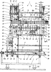
stationary machine frame 1 fixed on a machine table 2. The machine ta-
ble 2 is supported on rails 2b by way of rollers 2a. The machine frame 1
substantially consists of two frame plates 3, 4 of vertical arrangement,
which are parallel to each other and spaced apart from each other; the
frame plates 3, 4 and the machine table 2 are screwed together by means
of angle brackets 5. The frame plates 3, 4 each have a circular opening
4
6, 7, the openings 6, 7 being in alignment with each other and defining
a central longitudinal axis 8 of the apparatus.
The frame plates 3, 4 are interconnected by means of a plurality of in-
s ternal connecting rods 9 disposed at equal angular distances relative to
each other, the connecting rods 9 and the frame plates 3 and 4 being
screwed together by means of nuts 10. These internal connecting rods 9
each have the same distance from the axis 8 and extend parallel to the
latter. Thus, the frame plates 3 and 4 and the connecting rods 9 with
the nuts 10 substantially form the machine frame 1.
Seen in the direction of production 11, a supporting plate 12 similar to
the frame plate 3 precedes the frame plate 3 shown on the right in Fig.
1. The supporting plate 12 is connected with the further frame plate 4
- shown on the left in Fig. 1 - by means of external connecting rods 13,
the screwed connection likewise being effected by means of nuts 10. The
external connecting rods 13 pass through the frame plate 3, i.e. there is
no screwed connection. The distance a between the supporting plate 12
and the adjacent frame plate 3 can be adjusted by interchangeable
spacers 14.
On the downstream side of the frame 1 seen in the direction of production
11, a lifting carriage 15 is arranged, comprising a supporting plate 16
similar to the supporting plate 12 and to the frame plates 3, 4. The sup-
porting plate 16 and a carriage wall 17 spaced out in the direction of
production 11, and a distance plate 18 disposed between the carriage
wall 17 and the supporting plate 16 and spacing same apart in the di- '
rection of production 11, and fasteners 19, for instance screws, joining
the supporting plate 16, the carriage wall 17 and the distance plate 18,
altogether substantially form the lifting carriage 15. The latter is guided
for displacement in the direction of production 11 on two horizontal
guideways 20 for instance formed by precision steel tubes located in the
machine frame 1 parallel to the axis 8. For the purpose of guidance free
from play, rollers 21 disposed at equal angular distances and bearing
against the tubular guideway 20 from outside are located three by three
ri .~ ~ ~ g
w~J~~
S
in the vicinity of the supporting plate 16 and in the vicinity of the
carriage wall 17, for free rotation in the lifting carriage 15. As seen in
Fig. 1, the lifting carriage is foreshortened. Its actual length in the di-
rection of production 11 is such as to ensure the displacement free from
tilting, of the supporting plate 16.
The lifting carriage 15 is driven by means of a lifting drive 22 in the
form of a linear drive , a pressure medium actuatable piston cylinder
drive in the concrete case. The piston rod 23 of the lifting drive 22 is
l0 fixed to the lifting carriage 15. The opposite end of the cylinder 24 of
the lifting drive 22 is fixed to an abutment 25 displaceable in the direc-
tion of production in relation to the frame plate 3. By way of a spindle
27 rotatable by a crank 26, the abutment 25 in the form of a spindle nut
is supported on a spindle bearing 28 mounted on the frame plate 3. By
rotation of the crank 26 and thus of the spindle 27, the abutment 25 and
thus the cylinder 24 of the lifting drive 22 is adjusted in relation to the
frame 1 in the direction of production 11 or in a direction opposite to the
direction of production 11.
The supporting plates 12, 16 likewise have openings 29, 30 lapping the
openings 6, 7. Concentrically of the axis 8, funnel-shaped pipe guiding
sockets 31, 32 are screwed on the supporting plate 12 leading in the di-
rection of production 11 and on the frame plate 4 turned away from the
latter. The openings 6, 7, 29, 30 and the pipe guiding sockets 31, 32
define a pipe duct 32a that extends concentrically of the central longi-
tudinal axis 8.
In the direction of production 11 a pipe 33 is insertable through the pipe
guiding sockets 31, 32 into the pipe duct 32a, the spigot 34 of the pipe
33 leading for insertion in the direction of production 11. A socket 35 is
integrally molded on the rear end of the pipe 33 in the direction of pro-
duction 11. The pipe 33 consists of plastics and is formed as a corrugat-
ed pipe, i.e. it comprises annular elevations 36 alternating with annular
impressions 37 located between two such elevations 36. The pipe 33 can
be a so-called plain corrugated pipe or also a twin-wall pipe which, in
.,
6
addition to the external corrugated pipe, has a smooth cylindrical inter-
nal pipe that is connected with the external pipe in the vicinity of the
annular impressions 37 inside the pipe. Such plain corrugated pipes or
corrugated twin-wall pipes are generally known and commercial. Corru-
gated twin-wall pipes are for instance known from U.S. patent 4 930 936,
from which it is equally known to mold a socket 3S in one piece with
such pipes 33.
The guiding socket 31 mounted on the support plate 12 has an internal
l0 guide face 38, of which the inside diameter slightly exceeds the outside
diameter of the socket 3S of a tube 33, for the cutting of which the
apparatus is set. The pipe-guiding sockets 31, 32 are exchanged when
the apparatus is switched to another pipe diameter.
A plurality of holding and centering levers 39, 40 - six in the present
case - arranged at equal angular distances relative to each other are
disposed on the support plate 12 and on the frame plate 4 turned away
from the latter. In like arrangement, holding and centering and con-
veying levers 41 are disposed on the support plate 16 of the lifting
carriage 15 on the side facing the adjacent frame plate 4. Stop levers
42, again of like arrangement, are disposed on the rear side, seen in
the direction of production 11, of the support plate 16 of the lifting
carriage 1S. All the levers 39, 40, 41, 42 are double-armed levers which,
in a central portion, are pivotably supported on the supporting plate 12,
the frame plate 4 and the supporting plate 16, respectively, by means of
a pivot bearing 43, and that in a plane normal to the axis 8. At their
inner ends facing the axis 8, the levers 39, 40, 41 have clamping seg-
ments 4 suited to the cross-sectional area of the annular impressions 37
of the pipe 33 and able to engage with the latter. The stop levers 42 are
provided with stop segments 45 of similar form. The segments 44, 45 are
interchangeably mounted on the levers 39 to 42. In addition to the re-
spective clamping segment 44, a clamping element 44a projecting towards
the supporting plate 12 is mounted on the holding and centering levers 39
disposed on the supporting plate 12 and bears against the external rim
of the socket 35 when the pipe 33 has been pushed through the apparatus
ct ~ ~! -~ rl r7
7
to such an extent that referred to the axis 8, the face - not shown - of
the socket 3S is located between the clamping egments 44 of the holding
arid centering levers 39 and the supporting plate 12. Further, an optical
sensor 44b is attached to a clamping segment 44 of a holding and center-
s ing lever 40, the optical sensor 44b detecting whether the mentioned
clamping segment 44 is in an annular impression 37 of the pipe 33. Fur-
ther, an optical sensor 44c of the same type is provided on a stop seg-
ment 4S of a stop lever 42, detecting whether the stop segment 4S is in
the position of an impression 37 of the pipe 33. These optical sensors 44b
l0 and 44c are connected with a control unit not shown. They pass a signal
to the control unit, which means that the annular impressions 37 of the
pipe 33 have taken their correct axial and radial position referred to the
axis 8.
15 For the purpose of pivoting the levers 39, 40, 41, 42 respectively posi-
tioned on a plate 12, 4, 6, a pivoting drive ring 46, 47, 48, 49, which
is located in guide rollers SO supported on the respective plate 12, 4,
16, is mounted on the respective plate 12, 4, 16. The guide rollers SO
enclose the outside of the respective ring 46 to 49 so that it can be ro-
20 tated or pivoted about the axis 8. On their outer ends, the levers 39 to
42 each have a pivoting roller S1 engaging with a recess in the respec-
tive ring 46 to 49 so that when the respective ring 46 to 49 is pivoted
about the axis 8, the associated levers 39 to 42 are pivoted about the
respective pivot bearing 43, whereby the segments 44 and 4S, respective-
25 ly, change in distance relative to the axis 8. The extreme positions, i.e.
the position closest to the axis 8 and the position the most remote from
the axis 8, of the segments 44 and 4S is shown in a dashed line on the
right in Fig. 2.
30 Pivoting drives S3, S4, SS, S6 in the form of linear drives are provided
for pivoting the pivoting drive rings 46 to 49. They are pressure medium
actuatable piston cylinder drives of which the piston rod S7 is articulat-
ed on bearing levers S8 projecting outwards radially to the axis 8, of
the rings 46 to 49. The cylinders S9 of the pivoting drives S3 to S6 are
35 each articulated on carriage-type abutments 60 in the form of a spindle
s~ .~ ~, .1 a~
.n.. fd a
8
nut, which are disposed on a spindle bearing 63 serving as a guide to
be displaceable and consequently adjustable by means of a spindle 61
with a crank handle 62. The stroke b shown on the left in Fig. 1, of a
pivoting drive 53 to 56 for pivoting a segment 44, 45 into a position of
engagement with the corresponding impression 37 of the pipe 33 and out
of it into a position of release from the pipe 33 is dimensioned such that
the two mentioned positions are attained. Adjustment of the basic position
of the segments 44 to the respective diameter of the pipe 33 takes place
by displacing the abutment 60 by means of the spindle 61 on the spindle
l0 bearing 63.
A saw support 64 is disposed on each of an internal connecting rod 9
and an external connecting rod 13 which are assigned to each other in
pairs. It has two fastening holes 65 parallel to each other, through
which the connecting rods 9 and 13 are passed, one side of the saw sup-
port 64 bearing against stop collars 66 on the connecting rods 9 and 13.
Distance sleeves 67 are provided on the other side, bearing against the
frame plate 3.
A carriage guide 68 is disposed for linear displacement on the saw car-
rier 64; it is displaceable by means of a spindle 69, and that between
an adjacent and a distant and any desired intermediate position referred
to the axis 8. The distant position is shown in Fig. 3, top, whereas the
adjacent extreme position is shown in Fig. 3, bottom. A carriage 70a
supporting a mounting plate 70 is displaceably guided on this carriage
guide 68 and is drivable by means of a positioning motor 71, for in-
stance a stepping motor. A saw driving motor 73, again displaceable for
a short adjusting path by means of a spindle 72, is disposed on the car-
riage 70a. Further, bearing brackets 74 for a shaft 75 of a saw 76 are
arranged on this carriage 70a. These bearing brackets 74 are not adjust-
able in relation to the carriage 70a. The axis 77 of the shaft 75 and the
axis 78 of the saw driving motor 73 rest in a radial plane 79 common
with the axis 8 and extend in parallel to the latter. The displacement of
the carriage 70a by means of the positioning motor 71 as well as the ad-
justing motions by means of the spindles 69, 72 take place parallel to
r;.r i cJ .~
9
this radial plane 79.
Circular saw blades 80 are fixed on the shaft 75, which are disposed at
a distance c relative to each other by means of distance sleeves 81, the
distance c being identical with the spacing d of the annular elevations
36 and the annular impressions 37, respectively, of the pipe 33.
A pulley 82 is disposed on the shaft 75 at an end corresponding to the
position of the driving motor 73. Moreover, two bearings 83 are arranged
on the shaft 75. The saw 76 is mounted by the mentioned components be-
ing clamped together on the shaft 75 by means of threaded nuts 74. The
bearing covers 85 being removed, the two bearings 83 are the placed into
the bearing brackets 74 and then the bearing covers 85 are fixed each
by means of a screw 86. So, the replacement of a saw 76 takes place
very rapidly.
Likewise, a pulley 87 is non-rotatably mounted on the driving motor 73.
A belt 88 is swung around the two pulleys 82, 87. The spindle 72 for ad-
justing the driving motor 73 solely serves to tighten the belt 88. The
stroke of this spindle 72 can be comparatively small. The pulleys 82 and
87 have a transmission ratio of 1:1, however deviations are possible. As
illustrated in Fig. 3, upper half, the transmission ratio is 1:1 when
circular saw blades 80 of a comparatively great diameter a are used. As
seen in Fig. 3, lower half, the transmission ratio of the pulleys 82 and
87 is approximately 2:1 when circular saw blades 80' of a comparatively
small diameter e' are used. In this way the peripheral velocity of the
circular saw blades 80, 80' can be kept constant, given an identical
speed of the saw driving motor 73. Circular saw blades 80 of a compara-
tively great diameter a are used for producing slots 89 in the annular
impressions 37 of the pipe 33, when the latter has a comparatively great
diameter f, as shown in Fig. 3, top. When, however, the pipe 33' has a
comparatively small diameter f , circular saw blades 80' of smaller diam-
eter e' are used.
wy .~ : y .r, c
The operation of the apparatus is as follows, reference being made to one
pipe 33 only.
The piston rods 57 of the pivoting drives 53 to 55 are retracted into the
5 corresponding cylinder 59, i.e. the levers 39 to 41 are pivoted such that
the clamping segments 44 are in an outer position free from a pipe 33.
The piston rod 57 of the pivoting drive 56 is extracted from its cylinder
59 so that the stop lever 42 is in a position in which its stop segment 45
has taken its radially inner position - referred to the axis 8. The piston
10 rod 23 of the lifting drive 22 is moved into the cylinder 24 so that the
lifting carriage 15 is in its position next to the adjacent frame plate 4.
Now a pipe 33, with its spigot 34 ahead, is pushed through the pipe
guiding socket 31 and then through the pipe guiding socket 32 in the di-
rection of production 11 until the first annular elevation 36 of the pipe
33 comes to bear against the stop segments 45 of the stop levers 42. This
is where the pushing motion is being stopped. The pipe 33 has taken its
position referred to the direction of the axis 8. A signal of the sensor
44c confirms the correct axial and radial initial position of the pipe 33,
enabling the subsequent operations. Then the pivoting drives 53, 54, 55
are actuated for their piston rods 57 to exit so that the holding and
centering levers 39, 40 and the holding and centering and conveying
levers 41 are pivoted such that their clamping segments 44 mesh with the
annular impressions 37 assigned to them, of the pipe 33. Now the pipe
33, with its axis coinciding with the axis 8, is arrested axially and
tangentially and centered in relation to this axis 8, i.e. it cannot
escape radially to the axis 8 nor in the direction of the axis 8, nor can
it rotate about the axis 8. The optical sensor or sensors 44b signal that
the clamping segments 44 have taken the correct position referred to the
pipe 33, i.e. that the annular impressions 37 of the pipe 33 are in the
correct position relative to the circular saw blades 80 and 80', respec-
tively.
Now all the positioning motors ?1 of all the saws 76 are put in operation
so that the carriages 70a with the permanently operating saw driving
Eu -.~- ::~ ,z ;.,~ . ~!
11
motors 73 and the saws 76 driven by the latter are transported in rapid
motion as far as to the point of penetration into the associated annular
impressions 37 of the pipe 33. Right before the circular saw blades 80
reach the pipe wall 90 in the vicinity of the annular impressions 37,
slow saw advance is switched to and a slot 89 is cut by each saw blade
80 into the pipe wall 90 assigned to an impression 37. Once the desired
circumferential length of the slots 89 is realized as a result of the preset
depth of penetration of the saw blades 80 into the pipe wall 90, the po-
sitioning motors 71 are reversed and the carriages 70a with the saws 76
and the driving motors 73 are returned to the outer position in rapid
motion. For the pipe 33 not being subject to torque during the cutting of
the slots 89, the shafts 75 of the saws 76 are alternately driven in op-
posite directions corresponding to the arrows 91, 91' showing the direc-
tion of rotation for driving.
After the termination of such a slot cutting process, the pivoting drives
53; 54, 56 are actuated in such a way that the clamping segments 44 of
the holding and centering levers 39, 40 and the stop segments 45 of the
stop levers release the pipe 33. The clamping segments 44 of the holding
and centering and conveying levers 41 reamin in engagement with the
pipe 33. Now the lifting drive 22 is actuated in such a way that the
lifting carriage 15 is displaced by a stroke travel g in the direction of
production 11. The stroke travel g results from the number z of the saw
blades 80 multiplied by their distance c. Consequently g = z x c applies.
The stoke travel g exceeds the distance h of the external saw blades 80
of the shaft 75, to which h = (z - 1) x c applies. The strict maintenance
of this displacement of the lifting carriage 15 by the stroke travel g is
attained by adjustable limit stops 92, to which stop absorbers 92a are
assigned.
In this position the pivoting drives 53, 54 are again actuated so that the
clamping segments 44 of the holding and centering levers 39, 40 again
engage with annular impressions 37 of the pipe 33. The pipe 33 is again
centered and held. A new slot cutting procees is performed, taking place
as above described.
. :.
,, .~ r
~~re.~~~
12
When the socket 35 is finally moved into the pipe guiding socket 31, then
the clamping elements 44a of the associated holding and centering levers
39, which grip through window-type openings 93 of the guide face 38,
bear from outside against the end of the socket 35.
After slots 89 being cut into the pipe wall 90 even right beside the sock-
et 35, i.e. once the slotting of the pipe 33 has been finished, all the
levers 39, 40, 41 are pivoted such that their clamping segments 44 re-
lease the pipe 33. The pipe 33 is then removed from the apparatus in the
direction of production 11.
In the first cutting process the annular impressions 37 located between
the stop segments 45 and the first saw blade 80 facing them are not pro-
vided with slots 89. This does not matter because these impressions 37
are in the vicinity of the spigot 34 of the pipe that will take its place
in a socket 35 and is thus closed externally, when a plurality of pipes
33 are assembled, it being of no importance whether the socket 35 is in-
tegrally molded or whether a plug-on socket is used.
With pipes 33 of different spacing d of the annular impressions 37, the
adaption of the position of the holding and centering levers 39 takes
place by the modification of the position of the supporting plate 12 by
the spacers 14 being interchanged. The adaption of the position of the
clamping segments 44 of the holding and centering and conveying levers
42 is effected by corresponding adjustment of the lifting drive 22 by
means of the spindle 27. The modification of the position of the stop seg-
ments 4S, likewise in the direction of the axis 8, takes place by inter-
changing the stop levers 42, which is shown in dashed lines in Fig. 1.
The stop segments 45 thus take a different position in the direction of
the axis 8.
The specified apparatus serves to slot pipes not only of circular cross-
sectional area, but also of non-cross-sectional area. For instance,
catch-water foot pipes as known from U.S. patent 4 779 651 can be
provided with slots. In this case, the arrangement of the saws 76 must
~. ~ J
13
be adapted, in particular only a total of four or five saws 76 will be
necessary. Also, the arrangement of the levers 39, 40, 41, 42 must be
adapted correspondingly.
When the terms "to saw" and "circular sawing blades" 80 and 80' are
used, this also covers the term "to mill" and "disk milling cutter". In
this regard, there is no difference between circular sawing blades and
disk milling cutters.