Note: Descriptions are shown in the official language in which they were submitted.
~ 1 ... `
Z~3~97 `-~ -
HOUSING ~OI~ WORM-GEAR PRESS
Th- invention relate~ to ~he hou~ing o~ a ~win worm-gear
press fo~ aontinuou~ly conv~yin~, ~ixlng and/or kne~d~ng
m~di~ st elevated prossure, ln acaordanc- with tho
aharacterizing ~eature~ o~ Claim 1. The term ~xtrud~r h~
become eat~blish~d ~or apparat~ of thls type~ A
particularly lmport~nt embodi~ont of the pre~nt in~n~ion
applies to the hou~ing o~ an ~xtr~der whlah i6 called a
rotruder (r~rs~ ~xtruder) b~c~uBo a8 ~ r~Bult of the
r~vorsal of the direction of convoying the inner ~all of
th~ housing is undor a partlcul~rly great load and b~cau~o
as a r~ult of the ad~u&t~b~llty of at loa~t on~ lnsert
part optimization-of the 6¢~w ~xtrusion i8 m~de po~sible.
'.:
Continuou~ con~eying, mixing an~/or kneading of mediA is
p~rt of th~ ba~ic op~ratlon~ of p~oc-s8 ~ngin~-ring. Tho
~ate~ial ~or m~xing an~/or convoylng ~an be v~ry di~er-nt
~ub~t~nc-- Tho chomioal an~ phy~laal prop-rt~-s o~ th-so
sub~tan~e~, their ~tat~ o~ aggre~ation and th~ir b~h~viour
under pr~sur- ~nd heat c~n b~ aorrespondingly di~-r-nt
~he prlor art ~or 601ution~ provi~ed in mea~nia~l
engine~rlng, WhiOh ~xt-nd ~rom kn~ader~ f~r chocol~to
compo~itlon, the productlon o~ ~mifinished pla~lcs by
extru~lon and the procea-ing o~ flowa~le plastlc~ granul~
with a glas~ fibre content for ~n~ction moulding ~o th~
dl~posal of blologic~lly ~¢t~v- wa~te, correspond~ to this
v~ri~ty For all th~e ~ask~ th~r~ ~r- known m~chine~
which have, d~p~nd$ng on the r~qulr~m~nt~, cool~d or h~ate~
hou~ings and at least two rotatln~, mutually m~hlnq
aonvey~ng ~arews which produc- a preso~re ~ulld-~p by
forcibly conveylng th~ modlum in th- indi~lduAl~ alo~d
windings of th~ ~crew a~nne~, w~ t~out havlng ~ re~ctivo
~ ct on th- ~a~ trsn~por~. On~ Q~ th~ w sk point~ of
th~s construction i~ the ~ouaing, inc- th~ ~onv~ylng
pres~ur~ produces periph~ral 8tr~ ln th- hou~ing c~ing
,:
2~:~129~
- `` '' ~'`
2 ;
and the friction of the medium results in abrasion and wear
of the inner faces. In particular, this disadvantage
becomes important when processing abrasive media or when
the high pressures in the medium for the purpose of
increasing the frictional forces in the medium are
themselves advantageous. This is the case with kneading
tasks if the efficiency of kneading is increased or for ~;~
example in the case of a frictional reactor which is to be
operated at high operating pressures as a thermo-mechanical
process unit for preparing the cell walls of a biomass. `-
According to the prior art, either the entire housing of
the screws or, as an integrated plating of the housing, in
the form of the casing surface of the screws, is produced
from wear-resistant materials in order to locally protect `
the locations at risk from material abrasion. Cobalt and
nickel alloys according to DIN 8555 and hard metal alloys
of known type are regarded as a protection against wear.
'
The disadvantage of this solution is the relatively short
service life of the protection against wear at the exposed
locations. This is because it is precisely at the line of
- penetration of the screw casing where the mechanical
abrasion is the greatest that the plating has to be welded
and the localized reduction in the protection against wear
has to be accepted.
A further disadvantage of the twin screw extruders is the
fact that there is no means of optimizing the screw
extrusion in operation other than the complicated speed
regulation of the screws.
The object of the present invention is to enable adjustment
of the pressure build-up and the frictional forces within
the medium, for forcible conveying of the medium in the
screw channel of a twin screw extruder, with or without
thrust reversal, and to increase the service life of the
machine. -
Z131297 ~ -;
! ; ` .
3 ";
In accordance with the invention, this object is achieved
by the characterizing features of Claims 1 and 2.
The advantages achieved by the invention reside, i`~
substantially for existing tasks, in the increase in the !`: :
steadiness of the kneading output, despite a fluctuating ,,,
quality and quantity of the conveyed material (e.g. when
introducing and ejecting a batch), in the increase in the ,'''~
service life of the screw extruder and thus in the increase
in the availability thereof, and thanks to these advantages ';-
in the possibility of providing new processes.
The invention will be described by way of example with -
reference to the attached drawings, in which~
--:
Fig. 1 shows the longitudinal section through a screw ~'
extruder with thrust reversal, and
~ :~
Fig. 2 shows the cross-section through the screw extruder ~ ,
of Figure 1. ' ,
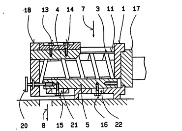
The screw extruder in Figures 1 and 2 comprises a housing ,~
1, the mutually meshing screws 2, 3 which are mounted in ' `
the front panel 18 and the bearing block 17 and are ~'`
constructed as a retruder, with reversing pitches, for the
purpose of thrust reversal, as reversible screws, ...... ~. '
Here, the housing 1 is provided around the screws 2, 3 with
the plating 11 and 12 and in the region of the penetration
line of t,,h,e screw casing of the screws 2, 3, as an -
extension to the protection against wear of the plating 11 '
and 12, with the insert parts 4 and 5. The term ';~
"reversible screw" indicates the particular property of
these screws, since both reversible screws change their
direction of conveying to the reverse direction by the
inversion of their pitch angles. A further important - -
~ Translator's Note: This sentence appears incomplete in the
German text.
`i ; 2131297 `:
property of the two reversible screws 2, 3 is the fact that
they rotate in opposite directions and in meshing manner.
In the region of the points of reversal of the pitch angles
of the screws 2, 3 the meshing is performed such that the
turning windings of the reversible screws 2, 3 roll on one
another in the manner of double helical gearwheels. From
the inlet 7, the medium passes into the screw channel of
the screws 2, 3 and is conveyed as a result of the rotation
in opposite directions forcibly in the individual turns,
which are closed (by the windings of the screw channel, the
housing inner wall comprising the plating 11, 12 and the
two insert parts 4, 5, and the mutually meshing screws 2,
3)-as far as the points of reversal. The mass transport
conveyed in the reverse direction presses against this mass
flow from the point of reversal. Depending on the counter-
pressure of the reverse direction, the frictional force in
the medium is increased. Finally, the winding of the
reverse direction allows the mass transport of the medium
to advance to the outlet 8.
If the adjusting spindle 20 is used to draw the insert part
5 towards the front panel 18 of the housing 1, the outlet
8 of the medium is closed or narrowed and as a consequence
of the forcible conveying the screw pressure increases.
Analogously the screw pressure is lowered if the outlet 8
is widened by pushing the insert part back. Operation of
the adjusting spindle 20 can be carried out both by hand or
J by a controlled or regulated drive (not shown). The
quality of the medium, such as a bearing of the screws 2,
3 which is located in the front panel 18, or a pressure
sensor (not shown) which is integrated between the insert
part 5 and the base of the housing 1, can serve as the
regulating variable2. For wear, the exposed zone of the
insert part 5 facing the outlet 8 is decisive. The
symmetrical form of the insert part 5 allows the insert
.
2 Translator's Note: This sentence appears incomplete in the -~
German text.
- ~ .
2131297
..
:
part 5 to be turned and thus the service life to be
- doubled. If the adjusting spindle 20 is arranged on the ~:
bearing block side 17, then it is possible to remove the
insert part 5, or indeed the insert part 4, through the
front panel 18 without dismantling the twin screw extruder.
.. '.' .
Depending on requirements, the housing 1 of the twin screw :
extruder can be provided with a casing (not shown) which is
common and/or divided as desired and which permits heating
and/or cooling. -~
,, .,, , , .. . . .. .. , . ~ , . .