Language selection

Search

Patent 2131448 Summary

Third-party information liability

Some of the information on this Web page has been provided by external sources. The Government of Canada is not responsible for the accuracy, reliability or currency of the information supplied by external sources. Users wishing to rely upon this information should consult directly with the source of the information. Content provided by external sources is not subject to official languages, privacy and accessibility requirements.

Claims and Abstract availability

Any discrepancies in the text and image of the Claims and Abstract are due to differing posting times. Text of the Claims and Abstract are posted:

  • At the time the application is open to public inspection;
  • At the time of issue of the patent (grant).
(12) Patent: (11) CA 2131448
(54) English Title: NOZZLE OF A SAND BLASTER FOR DUST-FREE BLASTING OF PLANAR SURFACES
(54) French Title: TUYERE DE DECAPEUSE POUR LE DECAPAGE SANS POUSSIERE DES SURFACES LISSES
Status: Expired and beyond the Period of Reversal
Bibliographic Data
(51) International Patent Classification (IPC):
  • B24C 5/04 (2006.01)
  • B05B 3/06 (2006.01)
  • B65B 3/06 (2006.01)
(72) Inventors :
  • KIESS, KARL HEINZ (Germany)
(73) Owners :
  • KARL HEINZ KIESS
(71) Applicants :
  • KARL HEINZ KIESS (Germany)
(74) Agent: ROBIC AGENCE PI S.E.C./ROBIC IP AGENCY LP
(74) Associate agent:
(45) Issued: 1999-04-13
(86) PCT Filing Date: 1993-11-08
(87) Open to Public Inspection: 1994-08-18
Examination requested: 1996-05-08
Availability of licence: N/A
Dedicated to the Public: N/A
(25) Language of filing: English

Patent Cooperation Treaty (PCT): Yes
(86) PCT Filing Number: PCT/EP1993/003125
(87) International Publication Number: WO 1994018004
(85) National Entry: 1994-09-02

(30) Application Priority Data:
Application No. Country/Territory Date
P 43 03 188.9 (Germany) 1993-02-04

Abstracts

English Abstract


A nozzle for a sand blaster for dust-free blasting of planar
surfaces comprises a tubular housing with a revolving nozzle
head which is connectable to a blast hose. The nozzle head
is covered with an end plate provided with inclined orifices
so that the nozzle head will be revolved by the throw of the
sand blasting material. For a better adaptability to
different demands for cleaning, each orifice is provided with
a slewable blast pipe which is mounted slewable with a socket
joint at the end plate.


French Abstract

Une buse de sableuse pour le décapage sans poussière de surfaces lisses comprend un corps tubulaire (1) pourvu d'une tête (3) de buse tournante pouvant être raccordée à un tuyau de décapage (2). La tête (3) de buse est recouverte d'une plaque terminale (4) pourvue d'orifices inclinés (7) afin que ladite tête (3) tourne sous l'effet de la projection du matériau de décapage au sable. Afin que le dispositif s'adapte à différentes nécessités de nettoyage, chaque orifice (7) est pourvu d'un conduit de décapage (9) monté pivotant, avec un raccord à emboîtement (10) au niveau de la plaque terminale (4).

Claims

Note: Claims are shown in the official language in which they were submitted.

WHAT IS CLAIMED IS:
1. Nozzle for a sand blaster for dust-free blasting of
planar surfaces with a blast material comprising a
tubular housing having a longitudinal axis, the housing
being connectable to a blast hose for the blast
material and provided with a revolving nozzle head
having an open end covered with an end plate including
inclined orifices, a blast pipe for each orifice, a
socket joint for each blast pipe including a ball
member cooperating with a cup for slewably mounting the
blast pipe on the end plate, and a fastening device for
fixing the blast pipe relative to the end plate in a
desired slewing position; whereby streams of the blast
material discharged from the blast pipes cause rotation
of the nozzle head.
2. Nozzle according to claim 1, wherein a pipe socket
forms the cup of the socket joint.
3. A nozzle for blasting planar surfaces with a blast
material including a granular abrasive and a fluid
medium, the nozzle comprising a tubular housing having
a longitudinal axis and adapted to be connected to a
hose, the housing having an open front end, a cover
plate closing the open front end and secured to the
housing, the cover plate including a plurality of pipe
sockets axes of which are inclined relative to the
longitudinal axis by an angle of less than 90° an
communicating an interior of the housing with an
exterior thereof, means permitting rotation of the
cover plate relative to the hose, an elongated blast
pipe for each pipe socket, a ball joint coupling the
blast pipe to the pipe socket, establishing fluid

communication between the housing interior and the
blast pipe, and permitting slewing of the blast pipe
relative to the pipe socket within a frustoconical
envelope for changing a direction of a stream of blast
material issuing from the blast pipe to thereby vary an
area of the planar surface impacted by the stream of
blast material as a result of rotation of the cover
plate and to further adjust a circle concentric with
the longitudinal axis to which the axis of the blast
pipe is tangential to therewith impart and control
rotation to the end plate relative to the hose, and
means for fixing the blast pipe relative to the end
plate in a selected position of the blast pipe.

Description

Note: Descriptions are shown in the official language in which they were submitted.


~ 31'f~
NOZZLE O~ A S~D BT-~STER FOR DUST-FREE BLASTING OF PLANAR
SURFACES
BACKGROUND OF THE INVENTION
The invention relates to a nozzle of a sand blaster for
dust-free blasting of planar surfaces comprising a tubular
housing connectable to a blast hose and provided with a
revolving nozzle head diffuser-like enlarged and covered
with an end plate which is provided with inclined orifices,
so that the nozzle head is revolved by the throw of the
sand blasting material.
For dust-free sand blasting of planar surfaces, sand
blasters are known which are provided with a hood mounted
on the nozzle head for covering the blasted area and
comprising installations for sucking off the blasting
material and the dust. The nozzle head is provided with a
venturi nozzle which directs the sand blasting material or
abrasive in a conical shape against the surface to be
blasted. The nozzle head is moved over the surface strip by
strip. For a revolving drive of the nozzle head, but
avoiding an additional motor, a blast nozzle is known from
DE 38 34 896 C2. The end plate of it is provided with
inclined orifices so that the diffuser-like enlarged nozzle
head is revolved by the throw of the abrasive-air mixture.
For adjustment to more or less wide blasting strips and/or
blasting effects on the surface to be blasted, the
disadvantage is that several end plates of different design
provided with appropriate orifices must be available and
stored.
SUMMARY OF THE INVENTION
It is therefore an object of the invention is to develop a
blast nozzle in such a way that higher adaptability to the
cleaning operations is possible.
A. ~
~" . .."

This problem is solved in accordance with the invention.
According to the present invention, there is provided a nozzle
for a sand blaster for dust-free blasting of planar surfaces
with a blast material, comprising a tubular housing having a
longitudinal axis, the housing being connectable to a blast
hose for the blast material and provided with a revolving
nozzle head having an open end covered with an end plate
including inclined orifices, a blast pipe for each orifice,
lo a socket joint for each blast pipe including a ball member
cooperating with a cup for slewably mounting the blast pipe
on the end plate, and a fastening device for fixing the blast
pipe relative to the end plate in a desired slewing position;
whereby streams of the blast material discharged from the
blast pipes cause rotation of the nozzle head.
Preferably, a pipe socket forms the cup of the socket joint.
According to the present invention, there is also provided a
nozzle for blasting planar surfaces with a blast material
including a granular abrasive and a fluid medium, the nozzle
comprising a tubular housing having a longitudinal axis and
adapted to be connected to a hose, the housing having an open
front end, a cover plate closing the open front end and
secured to the housing, the cover plate including a plurality
of pipe sockets axes of which are inclined relative to the
longitudinal axis by an angle of less than 9o and
communicating an interior of the housing with an exterior
thereof, means permitting rotation of the cover plate relative
to the hose, an elongated blast pipe for each pipe socket, a
ball joint coupling the blast pipe to the pipe socket,
establishing fluid communication between the housing interior
and the blast pipe, and permitting slewing of the blast pipe
relative to the pipe socket within a frustoconical envelope
for changing a direction of a stream of blast material issuing
from the blast pipe to thereby vary an area of the planar
,~ .c

~ / 3~
2a
surface impacted by the stream of blast material as a result
of rotation of the cover plate and to further adjust a circle
concentric with the longitudinal axis to which the axis of the
blast pipe is tangential to therewith impart and control
rotation to the end plate relative to the hose, and means for
fixing the blast pipe relative to the end plate in a selected
position of the blast pipe.
In accordance with the invention, the blast pipes allocated
to the end plate are adjustable into the most effective
position for cleaning operations. sy a radial adjustment
the width of blasted strip can be enlarged or reduced and
by a tangential adjustment the inclination of the blasting
may be changed. Depending on the nature of the material to
be blasted and the pollution, the best adaptability can be
achieved by adjusting the blast pipes. Where, for example a
hard coat of dirt is to be blasted, an appropriate hard
blasting of the surface is adjustable.
The bearing of the blast pipes on the end plate may be made
in different ways. Preferably, the blast pipe is carried
slewable by a socket ~oint at the end plate. At this, a
pipe socket provided with a ball cup for the socket joint
may be attached at the edge of each orifice. Besides that,
the socket ~oint preferably is provided with fastening
devices which fix the blast pipe in the adjusted slewing
position.
~RIEF DESCRIPTION OF T~IE DRAWINGS
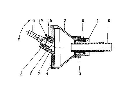
The drawings illustrate an example of the invention it is
Fig. 1 is a side view of a blast nozzle for dust-free
blasting of planar surfaces,

2b
Fig. 2 is a front end of the ~ub~ect of Fig. 1, and
Fig. 3 is a central cross-sectional view of the subject
of Fig. 1 wherein, for a better representation,
the section of the blast pipe is shown in a
=
A

~ 3/~
DESCRIPTION OF THE PREFERRED EMBODIMENTS
The blast nozzle for sand blasters for a dust-free blasting
of planar surfaces as shown in Fig. 1 substantially
consists of a tubular housing 1 with an equipment for
connecting a blast hose 2. At the front a nozzle head 3 is
provided which is enlarged diffuser-like. The nozzle head 3
is provided with an exchangeable end plate 4 which is
fastened by appropriate fixing devices, such as screws and
the like. Furthermore, but not shown in the drawing, the
blast nozzle is provided with a hood that is supplied with
suction installations.
As shown in Fig. 3, the conical nozzle head is provided
with a collar 5, which is mounted revolvingly on the
housing 1 by means of a rolling bearing 6. The blasting
material, consisting of the carrier gas with the abrasive
sand or other particles, is blown through the blast hose 2
into the nozzle head 3. The end plate 4 mounted in the
frontal opening of the nozzle head 3 is supplied with four
inclined drill-hole-like orifices 7, which are arranged
transversely through the head plate 4 in one rotary
direction. The axes of these inclined orifices 7 run in
such a way that a rotation of the nozzle head 3, in the
direction of the arrow shown in Fig. 2, is effected. As
shown particularly in Fig. 3, a pipe socket 8 is attached
at the edge of each orifice 7. Each pipe socket 8 forms a
support for one blast pipe 9. For a slewable bearing each
blast pipe 9 is provided with a socket joint 10, that is
slewable in a ball cup ll, allocated to the pipe socket 8
so that the direction of the blast pipe can be freely
selected within a frustoconical envelope.
An adjusting nut 12 permits the fixing of the blast pipe 9
in its adjusted position. The pipe sockets 8, allocated to
the orifices 7, are fixed in the same inclined position as
the corresponding orifices 7, as shown particularly clearly
in Fig. 2. On the other hand, the blast pipes 9 can be ad-
justed individually by means of the socket joint 10.
,. ,
,~3

Both the number of blast pipes 9 allocated to the nozzle
head 3 and the slewable bearing at the end plate 4, may be
applied in different versions. It is possible, for example
to use a simple swivel bearing instead of a socket joint,
whereby bearing necks can be provided at the blast pipe 9,
which are placed in the corresponding drills of the pipe
socket 8 or of the orifice 7. The slewing axis of such a
bearing can lie in different ways, with regard to middle
axis of the discoid end plate 4, in an inclined position,
if possible, but also in positions where the slewing axis
is arranged radial or tangential. The orifice 7 can have
other profiles instead of a cylindrical one.

Representative Drawing
A single figure which represents the drawing illustrating the invention.
Administrative Status

2024-08-01:As part of the Next Generation Patents (NGP) transition, the Canadian Patents Database (CPD) now contains a more detailed Event History, which replicates the Event Log of our new back-office solution.

Please note that "Inactive:" events refers to events no longer in use in our new back-office solution.

For a clearer understanding of the status of the application/patent presented on this page, the site Disclaimer , as well as the definitions for Patent , Event History , Maintenance Fee  and Payment History  should be consulted.

Event History

Description Date
Inactive: IPC from MCD 2006-03-11
Time Limit for Reversal Expired 2005-11-08
Letter Sent 2004-11-08
Grant by Issuance 1999-04-13
Inactive: Final fee received 1998-11-19
Pre-grant 1998-11-19
Letter Sent 1998-10-14
Notice of Allowance is Issued 1998-10-14
Inactive: Approved for allowance (AFA) 1998-09-17
Inactive: Status info is complete as of Log entry date 1998-01-26
Inactive: Application prosecuted on TS as of Log entry date 1998-01-26
Request for Examination Requirements Determined Compliant 1996-05-08
All Requirements for Examination Determined Compliant 1996-05-08
Application Published (Open to Public Inspection) 1994-08-18

Abandonment History

There is no abandonment history.

Maintenance Fee

The last payment was received on 1998-09-11

Note : If the full payment has not been received on or before the date indicated, a further fee may be required which may be one of the following

  • the reinstatement fee;
  • the late payment fee; or
  • additional fee to reverse deemed expiry.

Patent fees are adjusted on the 1st of January every year. The amounts above are the current amounts if received by December 31 of the current year.
Please refer to the CIPO Patent Fees web page to see all current fee amounts.

Fee History

Fee Type Anniversary Year Due Date Paid Date
Request for examination - small 1996-05-08
MF (application, 4th anniv.) - small 04 1997-11-10 1997-09-10
MF (application, 5th anniv.) - small 05 1998-11-09 1998-09-11
Final fee - small 1998-11-19
MF (patent, 6th anniv.) - small 1999-11-08 1999-10-26
MF (patent, 7th anniv.) - small 2000-11-08 2000-10-10
MF (patent, 8th anniv.) - small 2001-11-08 2001-10-11
MF (patent, 9th anniv.) - small 2002-11-08 2002-10-09
MF (patent, 10th anniv.) - small 2003-11-10 2003-10-02
Owners on Record

Note: Records showing the ownership history in alphabetical order.

Current Owners on Record
KARL HEINZ KIESS
Past Owners on Record
None
Past Owners that do not appear in the "Owners on Record" listing will appear in other documentation within the application.
Documents

To view selected files, please enter reCAPTCHA code :


To view images, click a link in the Document Description column. To download the documents, select one or more checkboxes in the first column and then click the "Download Selected in PDF format (Zip Archive)" or the "Download Selected as Single PDF" button.

List of published and non-published patent-specific documents on the CPD .

If you have any difficulty accessing content, you can call the Client Service Centre at 1-866-997-1936 or send them an e-mail at CIPO Client Service Centre.


Document
Description 
Date
(yyyy-mm-dd) 
Number of pages   Size of Image (KB) 
Abstract 1995-09-15 1 53
Claims 1995-09-15 1 38
Drawings 1995-09-15 1 32
Description 1995-09-15 4 182
Abstract 1997-02-04 1 15
Description 1997-02-04 6 211
Claims 1997-02-04 2 57
Representative drawing 1999-04-07 1 10
Commissioner's Notice - Application Found Allowable 1998-10-13 1 163
Maintenance Fee Notice 2005-01-03 1 173
Fees 2003-10-01 1 29
Fees 1999-10-25 1 32
Fees 2000-10-09 1 30
Fees 2001-10-10 1 32
Fees 1998-09-10 1 41
PCT 1994-09-01 4 106
Correspondence 1998-11-18 1 29
Fees 2002-10-08 1 44
Fees 1997-09-09 1 36
Fees 1996-09-08 1 35
Fees 1995-10-03 1 40