Sélection de la langue

Search

Sommaire du brevet 2131448 

Énoncé de désistement de responsabilité concernant l'information provenant de tiers

Une partie des informations de ce site Web a été fournie par des sources externes. Le gouvernement du Canada n'assume aucune responsabilité concernant la précision, l'actualité ou la fiabilité des informations fournies par les sources externes. Les utilisateurs qui désirent employer cette information devraient consulter directement la source des informations. Le contenu fourni par les sources externes n'est pas assujetti aux exigences sur les langues officielles, la protection des renseignements personnels et l'accessibilité.

Disponibilité de l'Abrégé et des Revendications

L'apparition de différences dans le texte et l'image des Revendications et de l'Abrégé dépend du moment auquel le document est publié. Les textes des Revendications et de l'Abrégé sont affichés :

  • lorsque la demande peut être examinée par le public;
  • lorsque le brevet est émis (délivrance).
(12) Brevet: (11) CA 2131448
(54) Titre français: TUYERE DE DECAPEUSE POUR LE DECAPAGE SANS POUSSIERE DES SURFACES LISSES
(54) Titre anglais: NOZZLE OF A SAND BLASTER FOR DUST-FREE BLASTING OF PLANAR SURFACES
Statut: Périmé et au-delà du délai pour l’annulation
Données bibliographiques
(51) Classification internationale des brevets (CIB):
  • B24C 5/04 (2006.01)
  • B05B 3/06 (2006.01)
  • B65B 3/06 (2006.01)
(72) Inventeurs :
  • KIESS, KARL HEINZ (Allemagne)
(73) Titulaires :
  • KARL HEINZ KIESS
(71) Demandeurs :
  • KARL HEINZ KIESS (Allemagne)
(74) Agent: ROBIC AGENCE PI S.E.C./ROBIC IP AGENCY LP
(74) Co-agent:
(45) Délivré: 1999-04-13
(86) Date de dépôt PCT: 1993-11-08
(87) Mise à la disponibilité du public: 1994-08-18
Requête d'examen: 1996-05-08
Licence disponible: S.O.
Cédé au domaine public: S.O.
(25) Langue des documents déposés: Anglais

Traité de coopération en matière de brevets (PCT): Oui
(86) Numéro de la demande PCT: PCT/EP1993/003125
(87) Numéro de publication internationale PCT: WO 1994018004
(85) Entrée nationale: 1994-09-02

(30) Données de priorité de la demande:
Numéro de la demande Pays / territoire Date
P 43 03 188.9 (Allemagne) 1993-02-04

Abrégés

Abrégé français

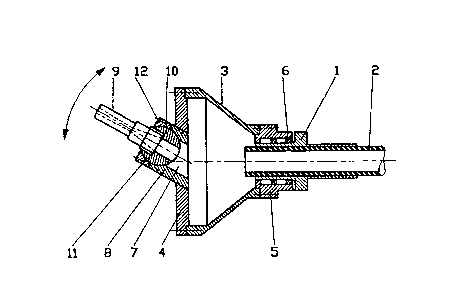
Une buse de sableuse pour le décapage sans poussière de surfaces lisses comprend un corps tubulaire (1) pourvu d'une tête (3) de buse tournante pouvant être raccordée à un tuyau de décapage (2). La tête (3) de buse est recouverte d'une plaque terminale (4) pourvue d'orifices inclinés (7) afin que ladite tête (3) tourne sous l'effet de la projection du matériau de décapage au sable. Afin que le dispositif s'adapte à différentes nécessités de nettoyage, chaque orifice (7) est pourvu d'un conduit de décapage (9) monté pivotant, avec un raccord à emboîtement (10) au niveau de la plaque terminale (4).


Abrégé anglais


A nozzle for a sand blaster for dust-free blasting of planar
surfaces comprises a tubular housing with a revolving nozzle
head which is connectable to a blast hose. The nozzle head
is covered with an end plate provided with inclined orifices
so that the nozzle head will be revolved by the throw of the
sand blasting material. For a better adaptability to
different demands for cleaning, each orifice is provided with
a slewable blast pipe which is mounted slewable with a socket
joint at the end plate.

Revendications

Note : Les revendications sont présentées dans la langue officielle dans laquelle elles ont été soumises.


WHAT IS CLAIMED IS:
1. Nozzle for a sand blaster for dust-free blasting of
planar surfaces with a blast material comprising a
tubular housing having a longitudinal axis, the housing
being connectable to a blast hose for the blast
material and provided with a revolving nozzle head
having an open end covered with an end plate including
inclined orifices, a blast pipe for each orifice, a
socket joint for each blast pipe including a ball
member cooperating with a cup for slewably mounting the
blast pipe on the end plate, and a fastening device for
fixing the blast pipe relative to the end plate in a
desired slewing position; whereby streams of the blast
material discharged from the blast pipes cause rotation
of the nozzle head.
2. Nozzle according to claim 1, wherein a pipe socket
forms the cup of the socket joint.
3. A nozzle for blasting planar surfaces with a blast
material including a granular abrasive and a fluid
medium, the nozzle comprising a tubular housing having
a longitudinal axis and adapted to be connected to a
hose, the housing having an open front end, a cover
plate closing the open front end and secured to the
housing, the cover plate including a plurality of pipe
sockets axes of which are inclined relative to the
longitudinal axis by an angle of less than 90° an
communicating an interior of the housing with an
exterior thereof, means permitting rotation of the
cover plate relative to the hose, an elongated blast
pipe for each pipe socket, a ball joint coupling the
blast pipe to the pipe socket, establishing fluid

communication between the housing interior and the
blast pipe, and permitting slewing of the blast pipe
relative to the pipe socket within a frustoconical
envelope for changing a direction of a stream of blast
material issuing from the blast pipe to thereby vary an
area of the planar surface impacted by the stream of
blast material as a result of rotation of the cover
plate and to further adjust a circle concentric with
the longitudinal axis to which the axis of the blast
pipe is tangential to therewith impart and control
rotation to the end plate relative to the hose, and
means for fixing the blast pipe relative to the end
plate in a selected position of the blast pipe.

Description

Note : Les descriptions sont présentées dans la langue officielle dans laquelle elles ont été soumises.


~ 31'f~
NOZZLE O~ A S~D BT-~STER FOR DUST-FREE BLASTING OF PLANAR
SURFACES
BACKGROUND OF THE INVENTION
The invention relates to a nozzle of a sand blaster for
dust-free blasting of planar surfaces comprising a tubular
housing connectable to a blast hose and provided with a
revolving nozzle head diffuser-like enlarged and covered
with an end plate which is provided with inclined orifices,
so that the nozzle head is revolved by the throw of the
sand blasting material.
For dust-free sand blasting of planar surfaces, sand
blasters are known which are provided with a hood mounted
on the nozzle head for covering the blasted area and
comprising installations for sucking off the blasting
material and the dust. The nozzle head is provided with a
venturi nozzle which directs the sand blasting material or
abrasive in a conical shape against the surface to be
blasted. The nozzle head is moved over the surface strip by
strip. For a revolving drive of the nozzle head, but
avoiding an additional motor, a blast nozzle is known from
DE 38 34 896 C2. The end plate of it is provided with
inclined orifices so that the diffuser-like enlarged nozzle
head is revolved by the throw of the abrasive-air mixture.
For adjustment to more or less wide blasting strips and/or
blasting effects on the surface to be blasted, the
disadvantage is that several end plates of different design
provided with appropriate orifices must be available and
stored.
SUMMARY OF THE INVENTION
It is therefore an object of the invention is to develop a
blast nozzle in such a way that higher adaptability to the
cleaning operations is possible.
A. ~
~" . .."

This problem is solved in accordance with the invention.
According to the present invention, there is provided a nozzle
for a sand blaster for dust-free blasting of planar surfaces
with a blast material, comprising a tubular housing having a
longitudinal axis, the housing being connectable to a blast
hose for the blast material and provided with a revolving
nozzle head having an open end covered with an end plate
including inclined orifices, a blast pipe for each orifice,
lo a socket joint for each blast pipe including a ball member
cooperating with a cup for slewably mounting the blast pipe
on the end plate, and a fastening device for fixing the blast
pipe relative to the end plate in a desired slewing position;
whereby streams of the blast material discharged from the
blast pipes cause rotation of the nozzle head.
Preferably, a pipe socket forms the cup of the socket joint.
According to the present invention, there is also provided a
nozzle for blasting planar surfaces with a blast material
including a granular abrasive and a fluid medium, the nozzle
comprising a tubular housing having a longitudinal axis and
adapted to be connected to a hose, the housing having an open
front end, a cover plate closing the open front end and
secured to the housing, the cover plate including a plurality
of pipe sockets axes of which are inclined relative to the
longitudinal axis by an angle of less than 9o and
communicating an interior of the housing with an exterior
thereof, means permitting rotation of the cover plate relative
to the hose, an elongated blast pipe for each pipe socket, a
ball joint coupling the blast pipe to the pipe socket,
establishing fluid communication between the housing interior
and the blast pipe, and permitting slewing of the blast pipe
relative to the pipe socket within a frustoconical envelope
for changing a direction of a stream of blast material issuing
from the blast pipe to thereby vary an area of the planar
,~ .c

~ / 3~
2a
surface impacted by the stream of blast material as a result
of rotation of the cover plate and to further adjust a circle
concentric with the longitudinal axis to which the axis of the
blast pipe is tangential to therewith impart and control
rotation to the end plate relative to the hose, and means for
fixing the blast pipe relative to the end plate in a selected
position of the blast pipe.
In accordance with the invention, the blast pipes allocated
to the end plate are adjustable into the most effective
position for cleaning operations. sy a radial adjustment
the width of blasted strip can be enlarged or reduced and
by a tangential adjustment the inclination of the blasting
may be changed. Depending on the nature of the material to
be blasted and the pollution, the best adaptability can be
achieved by adjusting the blast pipes. Where, for example a
hard coat of dirt is to be blasted, an appropriate hard
blasting of the surface is adjustable.
The bearing of the blast pipes on the end plate may be made
in different ways. Preferably, the blast pipe is carried
slewable by a socket ~oint at the end plate. At this, a
pipe socket provided with a ball cup for the socket joint
may be attached at the edge of each orifice. Besides that,
the socket ~oint preferably is provided with fastening
devices which fix the blast pipe in the adjusted slewing
position.
~RIEF DESCRIPTION OF T~IE DRAWINGS
The drawings illustrate an example of the invention it is
Fig. 1 is a side view of a blast nozzle for dust-free
blasting of planar surfaces,

2b
Fig. 2 is a front end of the ~ub~ect of Fig. 1, and
Fig. 3 is a central cross-sectional view of the subject
of Fig. 1 wherein, for a better representation,
the section of the blast pipe is shown in a
=
A

~ 3/~
DESCRIPTION OF THE PREFERRED EMBODIMENTS
The blast nozzle for sand blasters for a dust-free blasting
of planar surfaces as shown in Fig. 1 substantially
consists of a tubular housing 1 with an equipment for
connecting a blast hose 2. At the front a nozzle head 3 is
provided which is enlarged diffuser-like. The nozzle head 3
is provided with an exchangeable end plate 4 which is
fastened by appropriate fixing devices, such as screws and
the like. Furthermore, but not shown in the drawing, the
blast nozzle is provided with a hood that is supplied with
suction installations.
As shown in Fig. 3, the conical nozzle head is provided
with a collar 5, which is mounted revolvingly on the
housing 1 by means of a rolling bearing 6. The blasting
material, consisting of the carrier gas with the abrasive
sand or other particles, is blown through the blast hose 2
into the nozzle head 3. The end plate 4 mounted in the
frontal opening of the nozzle head 3 is supplied with four
inclined drill-hole-like orifices 7, which are arranged
transversely through the head plate 4 in one rotary
direction. The axes of these inclined orifices 7 run in
such a way that a rotation of the nozzle head 3, in the
direction of the arrow shown in Fig. 2, is effected. As
shown particularly in Fig. 3, a pipe socket 8 is attached
at the edge of each orifice 7. Each pipe socket 8 forms a
support for one blast pipe 9. For a slewable bearing each
blast pipe 9 is provided with a socket joint 10, that is
slewable in a ball cup ll, allocated to the pipe socket 8
so that the direction of the blast pipe can be freely
selected within a frustoconical envelope.
An adjusting nut 12 permits the fixing of the blast pipe 9
in its adjusted position. The pipe sockets 8, allocated to
the orifices 7, are fixed in the same inclined position as
the corresponding orifices 7, as shown particularly clearly
in Fig. 2. On the other hand, the blast pipes 9 can be ad-
justed individually by means of the socket joint 10.
,. ,
,~3

Both the number of blast pipes 9 allocated to the nozzle
head 3 and the slewable bearing at the end plate 4, may be
applied in different versions. It is possible, for example
to use a simple swivel bearing instead of a socket joint,
whereby bearing necks can be provided at the blast pipe 9,
which are placed in the corresponding drills of the pipe
socket 8 or of the orifice 7. The slewing axis of such a
bearing can lie in different ways, with regard to middle
axis of the discoid end plate 4, in an inclined position,
if possible, but also in positions where the slewing axis
is arranged radial or tangential. The orifice 7 can have
other profiles instead of a cylindrical one.

Dessin représentatif
Une figure unique qui représente un dessin illustrant l'invention.
États administratifs

2024-08-01 : Dans le cadre de la transition vers les Brevets de nouvelle génération (BNG), la base de données sur les brevets canadiens (BDBC) contient désormais un Historique d'événement plus détaillé, qui reproduit le Journal des événements de notre nouvelle solution interne.

Veuillez noter que les événements débutant par « Inactive : » se réfèrent à des événements qui ne sont plus utilisés dans notre nouvelle solution interne.

Pour une meilleure compréhension de l'état de la demande ou brevet qui figure sur cette page, la rubrique Mise en garde , et les descriptions de Brevet , Historique d'événement , Taxes périodiques et Historique des paiements devraient être consultées.

Historique d'événement

Description Date
Inactive : CIB de MCD 2006-03-11
Le délai pour l'annulation est expiré 2005-11-08
Lettre envoyée 2004-11-08
Accordé par délivrance 1999-04-13
Inactive : Taxe finale reçue 1998-11-19
Préoctroi 1998-11-19
Lettre envoyée 1998-10-14
Un avis d'acceptation est envoyé 1998-10-14
Inactive : Approuvée aux fins d'acceptation (AFA) 1998-09-17
Inactive : Renseign. sur l'état - Complets dès date d'ent. journ. 1998-01-26
Inactive : Dem. traitée sur TS dès date d'ent. journal 1998-01-26
Exigences pour une requête d'examen - jugée conforme 1996-05-08
Toutes les exigences pour l'examen - jugée conforme 1996-05-08
Demande publiée (accessible au public) 1994-08-18

Historique d'abandonnement

Il n'y a pas d'historique d'abandonnement

Taxes périodiques

Le dernier paiement a été reçu le 1998-09-11

Avis : Si le paiement en totalité n'a pas été reçu au plus tard à la date indiquée, une taxe supplémentaire peut être imposée, soit une des taxes suivantes :

  • taxe de rétablissement ;
  • taxe pour paiement en souffrance ; ou
  • taxe additionnelle pour le renversement d'une péremption réputée.

Les taxes sur les brevets sont ajustées au 1er janvier de chaque année. Les montants ci-dessus sont les montants actuels s'ils sont reçus au plus tard le 31 décembre de l'année en cours.
Veuillez vous référer à la page web des taxes sur les brevets de l'OPIC pour voir tous les montants actuels des taxes.

Historique des taxes

Type de taxes Anniversaire Échéance Date payée
Requête d'examen - petite 1996-05-08
TM (demande, 4e anniv.) - petite 04 1997-11-10 1997-09-10
TM (demande, 5e anniv.) - petite 05 1998-11-09 1998-09-11
Taxe finale - petite 1998-11-19
TM (brevet, 6e anniv.) - petite 1999-11-08 1999-10-26
TM (brevet, 7e anniv.) - petite 2000-11-08 2000-10-10
TM (brevet, 8e anniv.) - petite 2001-11-08 2001-10-11
TM (brevet, 9e anniv.) - petite 2002-11-08 2002-10-09
TM (brevet, 10e anniv.) - petite 2003-11-10 2003-10-02
Titulaires au dossier

Les titulaires actuels et antérieures au dossier sont affichés en ordre alphabétique.

Titulaires actuels au dossier
KARL HEINZ KIESS
Titulaires antérieures au dossier
S.O.
Les propriétaires antérieurs qui ne figurent pas dans la liste des « Propriétaires au dossier » apparaîtront dans d'autres documents au dossier.
Documents

Pour visionner les fichiers sélectionnés, entrer le code reCAPTCHA :


Pour visualiser une image, cliquer sur un lien dans la colonne description du document. Pour télécharger l'image (les images), cliquer l'une ou plusieurs cases à cocher dans la première colonne et ensuite cliquer sur le bouton "Télécharger sélection en format PDF (archive Zip)" ou le bouton "Télécharger sélection (en un fichier PDF fusionné)".

Liste des documents de brevet publiés et non publiés sur la BDBC .

Si vous avez des difficultés à accéder au contenu, veuillez communiquer avec le Centre de services à la clientèle au 1-866-997-1936, ou envoyer un courriel au Centre de service à la clientèle de l'OPIC.


Description du
Document 
Date
(aaaa-mm-jj) 
Nombre de pages   Taille de l'image (Ko) 
Abrégé 1995-09-15 1 53
Revendications 1995-09-15 1 38
Dessins 1995-09-15 1 32
Description 1995-09-15 4 182
Abrégé 1997-02-04 1 15
Description 1997-02-04 6 211
Revendications 1997-02-04 2 57
Dessin représentatif 1999-04-07 1 10
Avis du commissaire - Demande jugée acceptable 1998-10-13 1 163
Avis concernant la taxe de maintien 2005-01-03 1 173
Taxes 2003-10-01 1 29
Taxes 1999-10-25 1 32
Taxes 2000-10-09 1 30
Taxes 2001-10-10 1 32
Taxes 1998-09-10 1 41
PCT 1994-09-01 4 106
Correspondance 1998-11-18 1 29
Taxes 2002-10-08 1 44
Taxes 1997-09-09 1 36
Taxes 1996-09-08 1 35
Taxes 1995-10-03 1 40