Language selection

Search

Patent 2131559 Summary

Third-party information liability

Some of the information on this Web page has been provided by external sources. The Government of Canada is not responsible for the accuracy, reliability or currency of the information supplied by external sources. Users wishing to rely upon this information should consult directly with the source of the information. Content provided by external sources is not subject to official languages, privacy and accessibility requirements.

Claims and Abstract availability

Any discrepancies in the text and image of the Claims and Abstract are due to differing posting times. Text of the Claims and Abstract are posted:

  • At the time the application is open to public inspection;
  • At the time of issue of the patent (grant).
(12) Patent: (11) CA 2131559
(54) English Title: SAFETY TROLLEY RESTRAINT SYSTEM FOR RAILROAD BRIDGES
(54) French Title: SYSTEME DE RETENUE DE SECURITE A TROLLEY POUR PONTS FERROVIAIRES
Status: Deemed expired
Bibliographic Data
(51) International Patent Classification (IPC):
  • A62B 35/04 (2006.01)
(72) Inventors :
  • STRICKLAND, MICHAEL R. (Canada)
  • MACDONALD, KEVIN R. (Canada)
(73) Owners :
  • SMMART EQUIPMENT INC. (Not Available)
(71) Applicants :
(74) Agent: MARKS & CLERK
(74) Associate agent:
(45) Issued: 1997-11-25
(86) PCT Filing Date: 1994-01-07
(87) Open to Public Inspection: 1994-07-21
Examination requested: 1996-11-22
Availability of licence: N/A
(25) Language of filing: English

Patent Cooperation Treaty (PCT): Yes
(86) PCT Filing Number: PCT/IB1994/000042
(87) International Publication Number: WO1994/015673
(85) National Entry: 1994-09-06

(30) Application Priority Data:
Application No. Country/Territory Date
08/001,170 United States of America 1993-01-07

Abstracts

English Abstract


A safety trolley restraint system for easy attachment to
the rail of a railroad track crossing a bridge includes a
trolley carriage with opposed rollers clampable to the rail
so as to hold the trolley on the rail while permitting
rolling movement of the trolley on the rail and provides a
movable attachment point for the end of a safety line of a
personnel safety harness. The carriage includes two halves
pivoted together which may be opened to remove the trolley
from the rail and closed and locked to secure the trolley to
the rail. The trolley restraint attachment point is
preferably swingable from side to side with respect to the
rail and includes a swiveling mounted attachment eye for the
personnel safety line.


French Abstract

Cette invention concerne un système d'ancrage mobile de cordage de sécurité à montage facile sur rail de voie ferrée sur pont ferroviaire. Le système d'ancrage mobile est composé d'un chariot à galets opposés conçu pour être monté sur un rail de voie ferrée et pour se déplacer le long de celui-ci et aussi pour recevoir l'extrémité d'un cordage de sécurité attaché au harnais de sécurité d'un travailleur. Le chariot comprend deux moitiés réunis par une charnière que l'on peut ouvrir pour enlever le chariot du rail et refermer et verrouiller pour assujettir le chariot au rail. Le point d'ancrage du cordage est de préférence articulé pour pouvoir basculer d'un côté à l'autre du rail et comporte un anneau de fixation pivotant auquel attacher le cordage de sécurité.

Claims

Note: Claims are shown in the official language in which they were submitted.

- 6 -

We claim as our invention:

1. A safety trolley restraint system attachable to
a railroad track rail for rolling movement along the top
thereof so as to movably anchor the end of a personnel
safety line secured to a safety belt comprising, in
combination,
a carriage including a pair of frame halves
pivotally hinged together about a generally horizontally
extending pivot pin, each of said frame halves including
a pair of spaced-apart, generally vertical end plates and
a pair of generally horizontally extending, vertically
spaced-apart support plates, said end plates each having
a profile formed to engage and retain opposite sides of
said railroad track top therebetween, a plurality of
rollers journalled on axles secured between said
spaced-apart support plates in each of said frame halves,
each of said rollers having upper and lower end flanges with a
reduced diameter center section formed so as to engage
and retain opposite sides of said railroad track rail top
therebetween,
selectively engageable retaining means for securing
said hinged frame halves in closed position with said
rollers clamped so that said upper and lower end flanges
substantially envelop said rail top, said retaining means
also being disengageable for releasing at least one of
said hinged frame halves to pivot open and unclamp all of
said plurality of rollers on said one hinged frame half
from said rail top,
and restraint attachment means carried by said
carriage for securing said end of said personnel safety
line thereto.

2. A safety trolley restraint system as defined in
claim 1 wherein each of said carriage halves has a
generally inverted L-shaped configuration with a pair of

- 7 -

generally vertical end plates and a pair of spaced-apart,
horizontally extending support plates for supporting said
rollers.

3. A safety trolley as defined in claim 1 wherein
said retaining means includes a generally horizontally
extending lock pin disposed in offset relation to said
pivot pin for securing said frame halves in closed
position.

4. A safety trolley as defined in claim 1 wherein
said restraint attachment means includes a handle portion
mounted on said trolley carriage for pivotal movement
from side to side with respect to said rail.

5. A safety trolley as defined in claim 1 wherein
said restraint attachment means includes an attachment
eye mounted for swiveling movement with respect to said
trolley carriage.

Description

Note: Descriptions are shown in the official language in which they were submitted.


WO 94/15673 PCT/~94/00042
2131 5~i9
-- 1 --

SAFETY TROLLEY RES~ NT SYSTEM FOR RAILROAD BRIDGES

FI~T-n OF T~F~ 1NV~ 1ON

The present invention relates generally to railroad
perso~nel safety de~ices and more particularly concerns a
movable trolley re~traint ~ystem for use with a safety
line or fall arrest system for railroad peraonnel working
on railroad bridge6 and the like.

RA~ ~OIINI1 OF Th~: INV.. 11~ N :

When railroad tracks cross rivers, ravines and the
like, it i8 generally nPces6~ry to ~u~G~L the rails of
the track on bridges or tres~els. Frequently these
bridges and tre~e~ have been constructed with open
sides o~ho~rd of the rails. In other words, they do not
ha~e side~ or guard rails along the edges of the
bridge outside of the rails.

Rail bridges and track tressels, however, do require
periodic ;n~pection and ~-;nt~n~n~e of the ro~he~
including the track, ties, h~l lA~t and/or other
su~ol~ing material. Accordingly, railroad pe~ul~el must
cross the bridge or tressel, often on foot, to perform
their necessary ;n~pestion and maintenance function~ and
work. The ~hs~nce of sidewall6 and/or guardrails along
the edges of the bridges outboard the rails presents
potentially unsafe and hazardous situations for railroad
personnel who must walk along the tracks in connection
with their inspection and maintenance duties.


SUBSrlME SHEET (RULE 26)

W094/15673 l~lr~g1~'~0~'~
2131~59
-- 2

OR.~.CTS ~Nn SUMM~RY OF T~F. I~v~:NlION


It is the primary aim of the present invention to
provide a trolley restraint system that may be quickly,
conv~niently and securely attached for rolling . v~ --L
along the rails of railroad track eYten~;ng over rail
bridges, tressels and the like and to which a safety line
or per~onn~l fall arrest system and safety harness may be
att:, ~h~ .

A more detailed object is to provide such a trolley
restraint system that is relatively in~Yp~n~ive to make
and that can be directly attached to one of the railroad
track rails.

These and other features and advantages of the
invention will be more readily apparent upon reading the~5 following description of a preferred .~.-~ lified
i - t of the invention and upon reference to the
nying drawings wherein:

RRTF.F n~C~RTPTI~N OF T~. nRAWIN~


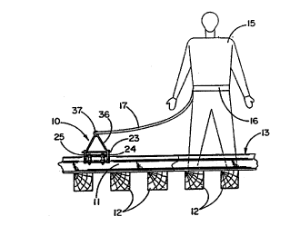
FIGVRE 1 is a r, - t~ry side elevation of a
portion of railroad track illustrating the safety trolley
restraint system of the present invention att~h~ to one
of the track rails and se~-u,ed by a safety line to a
railroad worker;
... .
FIG. 2 is an end view, partially in ~ection, of the
2S track, safety trolley and the rail worker shown in FIG.
l; ;.-: :

FIG. 3 iS an enlarged, fragmentary plan view of the
safety trolley of FIGS. 1 and 2;
. ~,. s. ,

~, ..
SU~STIME SHEET (RULE 26)

wo 94/15C73 ~ L9 1/00042
21315~9

FIG. 4 is an end view of the safety trolley of FIG.
3 subs~antially as seen along line 4-4 with the trolley
C~ r ~ ~~ on the rail and showing alternate positions of
the restraint attachment handle; and

FIG. 5 i6 an end view, similar to FIG. 4 with the
trolley llnc~ from the rail and with the att~ t
handle in a vertical position.

While the invention will be described and ~;~clo~ed
in cQ~--e Lion with certain preferred ~ s and
procedures, it is not inten~ to limit the inV~ntion to
those specific ~ c. Rather it i6 intended to
cover all such alternative ; '-~; ~ s and modifications
as fall within the spirit and scope of the invçnt;~n.

nRTATT.Fn nF.. ~'RTPTI~N OF 11~ Pli~ :~K~ nTMP~NI' ;
. '
~lrn;~ now to the drawings, there is shown in
FIGURE 1 a safety trolley restraint system 10 riding
along a rail 11 D~G Led by cross ties 12 of a railroad
track, indicated generally at 13. Alth~h not shown, it
will be understood that the railroad track 13 may be
~u~o,Led by a rail bridge or track tressel and that the
safety trolley restraint system 10 has particular utility
in such ci~. Lances. Tn~ee~ as shown in FIG. 1, an
individual 15, who may be a railroad inspector or track
, ;nt~nAnr~ worker, is st~n~;n~ on the track roA~he~
between the rails 11. It will also be understood that the
illustrated inspector or worker 15 wear~ a safety -~
harness, only generally indicated at 16, with an attArh
safety line or fall arrest sy~tem 17 which may be secured
to the safety trolley restraint system 10 of the present -~
invention.


SUBSTITUTE SHEET ~RIIlE 2

WO94/15673 PCT1~94/00042
:: 2131 ~9

In accordance with the present invention, the safety
trolley restraint system 10 includes a pair of generally
inverted L-~ihApe~ carriage frames 21 and 22 hinged
together by a pivot means such as a pin 23 or the like
adjacent the ends of the generally hori7ontAlly exten~;
legs of the f~ -e 21 and 22. Each of the carriage frames
21 and 22 includes a pair of generally vertical end
plates 24 and 25 and a pair of spaced apart, generally
hor~7~n~Al ~u~o,~ plates 26 and 27 rigidly secured
bet~_en the end plates. A~ shown in FIGS. 4 and 5, the
end plAte~ 24 and 25 each have a profile formed to engage
and retain opposite sides of the track top therebetween.
Axles 28 (illustrated here as boltg) are inserted through
~ju~Lv~iate openin~ in the Yu~o,L plates 26 and 27 for
jol~rnAlling a pair of rollers 30 on each of the hin~e~
carriage f, ~~ 21 and 22. The rollers are preferably
formed with upper and lower end flAn~es and a re~lce~
diameter center section formed 80 as to engage and retain
opposite sides of the rail top therebetween.

To secure the safety restraint trolley 10 on the
rail 11, the two halves of the carriage 21 and 22 are
pivoted to the open position as shown in FIG. 5. The
trolley 10 is then placed on the rail 11 with the rollers
30 on the main carriage frame 21 in engagement with one
side of the rail top. The other half of the carriage
frame 22 is then pivoted down to the closed position, as
shown in FIG. 4, with its rollers 30 in engay~ - t with
the other side of the rail top. A retA;n;ng pin 33 is
then inserted through aligned openings formed in the end
plates 24, 25 of the carriage halves 21 and 22 offset ~;-
from the pivot pin 23. Thus, it will be understood that
the rollers 30 capture the top or head of the rail 11
between them and attach the trolley 10 securely to the
rail 11 while permitting the trolley to ride freely along
the rail.


SUBSTITUTE SHEET (~UL~ 26)

- W094l~5~3 PCT~B9410W~2
2131~9
-- 5

In order to attach the safety line 17 of the .::
personnel harness 16 to the safety restraint trolley 10,
a restraint attachment means ~5 is provided on the
trolley lO. In the preferred ~ '~'; ~ t shown in the
drawings, the restraint attAf' - A~ means 35 comprises a
generally bail-like handle 36 pivotally mounted on the
end-plates 24, 25 of the trolley by the pivot pin 23 so
as to permit the handle to swing from side to side with
respe-t to the rail 11. Also the attA~ t means 35
preferably is fitted with an attachment eye 37 .- mte~
for swiveling . .~ ~ on the handle 36 and to which the .-
end of the j~elsol~lel safety line 17 may..be at~ hP~ such
as by a safety hook.

From the foregoing it will be appreciated that the
safe~y trolley restraint system of the present invention
includes a trolley that may be quickly and col-veniently
se~L~d on a railroad track rail for roll;ng ~ v. ~ t
along the rail so as to provide a movable attA~ ~ t
point to which a personnel safely line may be at~Ach~ to
arrest falls from rail bridges and the like.


SUBSTlTUrlE SHEET (RULE 26)

Representative Drawing
A single figure which represents the drawing illustrating the invention.
Administrative Status

For a clearer understanding of the status of the application/patent presented on this page, the site Disclaimer , as well as the definitions for Patent , Administrative Status , Maintenance Fee  and Payment History  should be consulted.

Administrative Status

Title Date
Forecasted Issue Date 1997-11-25
(86) PCT Filing Date 1994-01-07
(87) PCT Publication Date 1994-07-21
(85) National Entry 1994-09-06
Examination Requested 1996-11-22
(45) Issued 1997-11-25
Deemed Expired 2003-01-07

Abandonment History

There is no abandonment history.

Payment History

Fee Type Anniversary Year Due Date Amount Paid Paid Date
Application Fee $0.00 1994-09-06
Registration of a document - section 124 $0.00 1995-02-24
Reinstatement: Failure to Pay Application Maintenance Fees $200.00 1996-03-11
Maintenance Fee - Application - New Act 2 1996-01-08 $100.00 1996-03-11
Maintenance Fee - Application - New Act 3 1997-01-07 $100.00 1996-12-18
Final Fee $300.00 1997-07-16
Maintenance Fee - Patent - New Act 4 1998-01-07 $100.00 1998-01-07
Maintenance Fee - Patent - New Act 5 1999-01-07 $150.00 1998-12-16
Maintenance Fee - Patent - New Act 6 2000-01-07 $150.00 1999-12-09
Maintenance Fee - Patent - New Act 7 2001-01-08 $150.00 2000-12-20
Owners on Record

Note: Records showing the ownership history in alphabetical order.

Current Owners on Record
SMMART EQUIPMENT INC.
Past Owners on Record
MACDONALD, KEVIN R.
STRICKLAND, MICHAEL R.
Past Owners that do not appear in the "Owners on Record" listing will appear in other documentation within the application.
Documents

To view selected files, please enter reCAPTCHA code :


To view images, click a link in the Document Description column. To download the documents, select one or more checkboxes in the first column and then click the "Download Selected in PDF format (Zip Archive)" or the "Download Selected as Single PDF" button.

List of published and non-published patent-specific documents on the CPD .

If you have any difficulty accessing content, you can call the Client Service Centre at 1-866-997-1936 or send them an e-mail at CIPO Client Service Centre.


Document
Description 
Date
(yyyy-mm-dd) 
Number of pages   Size of Image (KB) 
Cover Page 1995-05-13 1 91
Abstract 1995-05-13 1 65
Claims 1995-05-13 2 139
Drawings 1995-05-13 2 118
Description 1995-05-13 5 419
Cover Page 1997-11-24 1 48
Claims 1997-03-04 2 58
Representative Drawing 1997-11-24 1 7
Fees 1996-12-18 1 62
Fees 1996-03-11 2 76
National Entry Request 1994-09-06 3 96
Prosecution Correspondence 1994-09-06 7 275
International Preliminary Examination Report 1994-09-06 13 420
National Entry Request 1994-09-13 5 227
Prosecution Correspondence 1996-11-22 1 35
Office Letter 1996-04-19 1 21
PCT Correspondence 1997-07-16 1 36
Prosecution Correspondence 1994-09-06 1 20