Note: Descriptions are shown in the official language in which they were submitted.
I''~. 1
21~1~7G
.~1A010
APPLICATION FOR PATENT
INVENTORS: JEAN-MICHEL D. HACHE
PIERRE A. MOULIN
WAYNE J. PHILLIPS
TITLE: MOTION COMPENSATION APPARATUS AND METHOD
OF GYROSCOPIC INSTRUMENTS FOR DETERMINING
HEADING OF A BOREHOLE
BACKGROUND OF THE INVENTION
1. Field of the Invention
This invention finds application in certain measurement systems which
determine
the heading of a borehole of a well. For example, the invention relates to
measuring-
while-drilling systems (MWD) which are designed to determine the position and
heading
of a tandemly connected sub near the drill bit of a drill string assembly in
an oil or gas
well borehole. The invention also finds application with wireline apparatus in
which one
or more down-hole instruments are designed to determine the position and
heading of
such instruments) during logging of an open hole borehole. In particular, the
invention
relates to the determination of the heading of the well from gyroscopic data
regarding the
earth's rotation and from accelerometer data regarding the earth's
gravitational field. Still
more particularly, the invention relates to an apparatus and method for
compensating
gyroscopic data for movement of a down-hole measurement instrument while a
heading
determination is being made.
_1_
213~.~'~~
,. Description of the Prior Art
Prior art measuring-while-drilling equipment has included magnetometers and
accelerometers disposed on each of three orthogonal axes of a measurement sub
of a
drill string assembly. Such measurement sub has typically been part of a
special drill
collar placed a relatively short distance above a drilling bit. The drilling
bit bores the earth
formation as the drill string is turned by a rotary table of a drilling rig at
the surface.
At periodic intervals, the drill string is stopped from turning so that the
measurement sub in the well boremay generate magnetometer data regarding the
earth's
magnetic field and accelerometer data regarding the earth's gravitational
field with respect
to the orthogonal axes of the measurement sub. The h vector from the
magnetometer
data and the g vector from the accelerometer data are then used to determine
the
heading of the well.
Such prior art method suffers from the fact that the earth's magnetic field
varies
with time and is affected by structures containing iron or magnetic ores in
the vicinity of
the measurement sub. Such variation leads to errors and uncertainty in the
determination
of the well heading.
Such variation in the heading determination of the measurement sub of a MWD
assembly, or a similar wireline instrument, can theoretically be eliminated by
adding
gyroscopes to each of the orthogonal axes of the measurement sub. In theory,
the
heading of the measurement sub can then be determined from accelerometer data
from
each of such axes and gyroscopic data from each of such axes. The
accelerometer data
is responsive to the gravitational field of the earth, while the gyroscopic
data is responsive
-2-
2 :~ 31 ~ '~ G
~ the rotational velocity of the earth with respect to inertial space.
Movement of the measurement sub (in the case of an MWD application) while
accelerometer and gyroscopic data is being taken can introduce an error into
the
determination of the earth's rotational velocity vector. Such movement may be
caused
by the "twist" or torque on the drill string after it is stopped from rotation
and it is
suspended from slips in the rig rotary table. Such twisting motion may occur
on land rigs
or on floating drilling rigs. Motion may also be produced while drilling has
been
suspended for a heading determination in a floating drilling rig where the
heave of the sea
causes the drill string to rise and fall in the borehole. Rotation of such
drill string may be
caused due to wave induced reciprocation of the measurement sub along a curved
borehole. Analogous errors may occur in the case of a wireline instrument.
SUMMARY OF THE INVENTION
A primary object of this invention is to provide an apparatus and method to
compensate for rotation induced errors for an instrument which uses gyroscopic
measurements for determining the heading of a borehole.
An important object of this invention is to provide a specific application of
the
invention in an apparatus and method for compensating gyroscopic measurements
of a
MWD measurement sub for rotation of the measurement sub itself while
accelerometer
and gyroscopic measurements are being made.
Another object of this invention is to provide a measurement apparatus and
method for determining the direction of a well through the use of
accelerometer and
-3-
2~~1~~'~
,,yroscopic measurements where possible corrections for rotation of the
apparatus are
measured using accelerometer and magnetometer measurements.
The objects identified above, along with other advantages and features of the
invention are illustrated in a preferred embodiment in a method and apparatus
for
reducing a source of error in measuring-while-drilling (MWD) equipment. The
invention
is also intended for application in wireline instruments. In the MWD
application of the
invention, a measurement sub is provided having a separate accelerometer,
magnetometer and gyroscope fixed along each of x, y and z axes of a sub
coordinate
system. An error is produced in gyroscope signals by the motion of the
measurement
sub in a drilling string while the string is suspended in a rotary table,
during the time that
a determination of the sub's heading with respect to the earth is conducted. A
unit vector
representing the earth's magnetic field with respect to the sub coordinate
system is
determined at a first time t~ and again at a second time t2 to produce unit
vectors fit, and
fi,~ and a difference unit earth magnetic field vector, 0~. A unit vector
representing the
earth's gravitational field with respect to the sub coordinate system is
determined at the
first time t, and again at the second time t2 to produce unit vectors fit, and
~,~ and a
difference unit earth's gravitational field vector, 0~. The time difference Ot
between t, and
t2 is also determined. From the vectors Ofi, fit,, 0~, fit, and the time
difference Ot, a
vector ~P representative of the angular rotation velocity of the measurement
sub or
"probe" is determined. Determination of ~p allows the gyroscopic vector
measured during
such time, 5~9, to be corrected to determine the actual earth's rotational
velocity vector fee.
Such vector and its components along with the accelerometer determination of
the earth's
-4-
~ 2131 ~7~
gravitational field allow a determination of the heading or
the direction of the well bore.
BRIEF DESCRIPTION OF THE DRAWINGS
The objects, advantages and features of the
invention will become more apparent by reference to the
drawings which are appended hereto and wherein like numerals
indicate like elements and wherein an illustrative embodiment
of the invention is shown, of which:
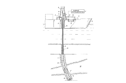
Figure 1 is a schematic representation of a
measuring-while-drilling system including a floating drill
ship and a downhole measurement sub constructed in accordance
with the invention;
Figure 2A is a schematic representation of the
downhole measurement sub with an accelerometer, magnetometer
and a gyroscope placed along orthogonal axes of the sub; and
Figure 2B is a schematic representation of a micro-
computer in the measurement sub with various computer programs
to determine the heading of the sub while it is downhole using
accelerometer data and gyroscopic data where the gyroscopic
data has been corrected for movement of the sub itself, and
Figures 3A-3F are flow charts illustrating variaus
computer programs referenced in Figure 2B.
DESCRIPTION OFTHE INDENTION
Figure 1 represents an illustrative embodiment of
the invention for a MWD application. As mentioned above, the
invention also may find application for a wireline measurement
system. A drilling ship S which includes a typical rotary
drilling rig system
- 5 _
71511-47
2~.~1~'~~
having subsurface apparatus for making measurements of formation
characteristics
while drilling. Although the invention is described for illustration in a MWD
drilling ship
environment, the invention will find application in MWD systems for land
drilling and with
other types of offshore drilling.
The downhole apparatus is suspended from a drill string 6 which is turned by a
rotary table 4 on the drill ship. Such downhole apparatus includes a drill bit
B and one
or more drill collars such as the drill collar F illustrated with stabilizer
blades in Figure 1.
Such drill collars may be equipped with sensors for measuring resistivity, or
porosity or
other characteristics with electrical or nuclear or acoustic instruments.
The signals representing measurements of instruments of collars F (which may
or
may not include the illustrated stabilizer blades) are stored downhole. Such
signals may
be telemetered to the surface via conventional measuring-while-drilling
telemetering
apparatus and methods. For that purpose, a MWD telemetering sub T is provided
with
the downhole apparatus. It receives signals from instruments of collar F, and
from
measurement sub M described below, and telemeters them via the mud path of
drill string
6 and ultimately to surface instrumentation 7 via a pressure sensor 21 in
standpipe 15.
Drilling rig system 5 includes a motor 2 which turns a kelly 3 by means of the
rotary table 4. The drill string 6 includes sections of drill pipe connected
end-to-end to
the kelly 3 and is turned thereby. The measurement sub or collar M of this
invention, as
well as other conventional collars F and other MWD tools, are attached to the
drill string
6. Such collars and tools form a bottom hole drilling assembly between the
drill string 6
and the drill bit B.
-6-
2 ~~:~~"~
As the drill string 6 and the bottom hole assembly turn, the drill bit B bores
the
borehole 9 through earth formations 32. An annulus 10 is defined as the
portion of the
borehole 9 between the outside of the drill string 6 including the bottom hole
assembly
and the earth formations 32. Such annulus is formed by tubular casing running
from the
ship to at least a top portion of the borehole through the sea bed.
Drilling fluid or "mud" is forced by pump 11 from mud pit 13 via standpipe 15
and
revolving injector head 8 through the hollow center of kelly 3 and drill
string 6, through
the subs T, M and F to the bit B. The mud acts to lubricate drill bit B and to
carry
borehole cuttings upwardly to the surface via annulus 10. The mud is delivered
to mud
pit 13 where it is separated from borehole cuttings and the like, degassed,
and returned
for application again to the drill string.
Measurement sub M, as illustrated in Figures 2A and 2B is provided to measure
the position of the downhole assembly in the borehole. Such borehole may be
curved
or inclined with respect to the vertical, especially in offshore wells. The
sub M includes
a structure to define x, y and z orthogonal axes. The z axis is coaxial with
sub M. On
each axis, a separate accelerometer, magnetometer and gyroscope is mounted. In
other
words, signals represented as GX, Hx, ~9X; Gy, Hy, ~9y; and GZ, HZ, S19Z are
produced and
applied to micro computer C disposed in sub M. Such signals are transformed to
digital
representations of the measurements of the instruments for manipulation by
computer C.
The signals Gx, Gy and GZ represent accelerometer output signals oriented
along
the x, y, z axes of the sub M; Hx, Hy, and HZ signals represent magnetometer
signals;
f~9X, ~19y, and ~9Z signals represent gyroscope signals.
_7_
In operation, drilling is stopped periodically, so that measurements of sub M
can
be performed to determine the heading ~ with respect to the vertical. In other
words, a
heading of ~=0 means that the well is inclining or heading toward earth's
geographic
north. A heading of ~=90° means that the well is inclining toward the
east, and so on.
The heading of the wellbore can be found using the tri-axial set of
accelerometers
GX, Gy, GZ and the tri-axial set of gyroscopes n9x, ~19y, S~9Z, to resolve the
earth's
gravitational field G and the earth's rotation vector ~e into their components
along three
orthogonal axes. The rotation vector ~8 represents angular velocity of the
earth with
respect to inertial space.
If the z axis of the measurement sub M is parallel to the axis of the
wellbore, the
i
direction of the borehole ~ can be determined from the vector components of G
and ne
as
tan (~) = 9X ~ dye ~Xe
~Z-~~ w)9Z
where ~ - G is a unit gravitational vector
with components gX, gy, 9Z
and
is a unit earth rotational vector
with components c~eX, c~ey, ~°Z
_8_
w:~3~~~'~~~
The term ~ G ~ , or absolute value of the accelerometer vector is defined as
The angular velocity vector fuels as measured by the gyroscopes is the sum of
the
angular velocity vector She of the earth and the angular velocity vector fop
of the probe.
In other words,
Sts - ~e + ~P
When the drill string 6 is suspended in the rotary table 4 by slips and is not
being
rotated, the motion of the measurement sub M in the borehole can be a large
source of
error for the gyroscopes. Such motion may result from twisting of the drill
string due to
residual torsional energy of the drill string after it is stopped from
turning. Such motion
may also take the form of up and down motion of the drill string caused by the
heave of
the drill ship S. As a result, measurement sub M slides up and down along the
curve of
an inclined borehole during the time of the heading determination. In other
words, the
gyroscopic measurements are corrupted with measurements of the rotation of the
sub
M itself.
This invention includes apparatus and a method for independently determining
the
rotation velocity vector Sip of the sub or "probe" relative to the earth, and
then determining
the earth's rotation vector ne by subtracting np from the rotation vector Sts
determined
from the gyroscopes.
_g_
The effect of the rotation of the measurement sub M relative to the earth on a
unit
vector fixed in the earth can be written as.
- o x ~P (2)
dt
For finite time steps, equation (2) becomes
00 - 0 x r?pOt (3)
The vector ~1p can be resolved into components parallel and perpendicular to 0
by
forming the cross products of the left and right hand sides of equation (3)
with o:
ooxo - (ox~Pot)xo,
0o X o - npot - (o ' npot)o
or
nPOt - ooxo + (o ' ~Pot)o (4)
In equation (4), spot is expressed as the sum of two components. The component
->
Oo x o is perpendicular to o. The term (o ' ~POt)o is parallel to o.
-10-
Because the gravitational field vector G (obtained from GX, Gy, GZ
accelerometers)
and the magnetic field vector H (obtained from HX, Hy, HZ magnetometers) are
both fixed
in the earth's frame of reference, two equations can be written for flpOt:
-.
iZp~t - ~~ X ~ + (~ ~ ~POt)~ (5)
and
~POt - DI1 X ~ + (~ ~ ~P~t)~ (6)
where ~ and ~ are unit vectors along the earth's gravitational field vector G
and the earth
i
magnetic field vector H,
->
= I .~ I ~ where ~ G ~ - J Gx2 + Gy2 + GZ2
and
fi = I .~ I° where ~ H ~ - J Hx2 + Hy2 + HZ2
Equating the right hand sides of equations (5) and (6), the equation becomes,
og x g + (~ ~ ~pnt)g = ofi x fi + (fi ~ nPot)fi (~)
-11 -
Two equations for the unknowns (~ ~ ~POt) and (~ ~ npOt), are obtained, for
example, by forming the dot products of equation (7) with any two linearly
independent
vectors ~ and B:
(~~ x ~) ~ A + (~ ~ ~POt)~ ~ A = (0~ x fit) A + (fit ~ nPOt)~ W (8)
(og x g) ~ s + (~ ~ ~Pot)g ~ a = (ofi x fi) s + (fi ~ s~Pot)fi ~~ (s)
i
Equations (8) and (9) can ,be put in matrix form and solved for (~ ~ f~p~t)
and
(fi ~ spot):
~ ~ A -~ ~ A ~ ~ f~P~t (0~ x ~) ~ A - (A~ x ~) A
(10)
~ ~B -~ ~B ~ ~~pOt (O~x~) ~B- (O~x~) B
One possible solution of equations (8) and (9) is to choose
A - 0~ x Li, and
B = D~x~.
-s
For such a selection, equation (8) can be solved directly for (~ - ~°
Ot) and
equation 9 solved directly for fi ~ npOt.
Figure 2B illustrates the microcomputer C which is disposed in measurement sub
M. Several computer programs or sub-routines are stored in micro computer C to
accept
-12-
2,~3~~76
representation of signals from each of the accelerometers,
magnetometers and gyroscopes.
Computer program 30, labeled Magnetometer Computer
program (unit vector) (see also the flow chart of Figure 3A),
accepts magnetometer signals HX, Hy and HZ signals at times tl
and t2 as received from clock 32. The unit vector fi is
determined at each of times tl and t2. A representation of
the unit vectors ~tl and ~t2 is applied to computer program 36
for further use. In the same way, the computer program or
sub--routine 34 accepts (see also the flow chart of Figure 3B)
signals GX, Gy, GZ from accelerometers of measurement sub M.
Computer program 34 determines unit gravitational field
vectors at the times tl and t2. Such vectors gtl and gt2 are
app:Lied to program 36.
The computer program 36, illustrated in Figure 3C,
first determines the difference between sequential
measurements of gtl and gt2 and Rtl and fit2. In other words,
a representation of Dg and efi is determined. The
representation of At, the time difference between the
sequential measurement times, is also applied to computer
program 36 (see Figure 3C).
Computer program 36 uses representations of ~g,g,
~fi,~ along with arbitrary vectors A and B (A and B selected to
be linearly independent of one another) to produce a
rep resent at ion of S~pAt . Either the gt 1 , or the gt 2 or the
mean value between such vectors may be used as g. Likewise,
the fitl or the fit2 or the mean value between such vectors may
be used as fi. The program 36 has a data input of At from
clock 32. Accordingly, the At representation is used with the
- 13 -
71511-47
2131576
represent at ions of S~pAt to produce represent at ions of Stpx,
Stpy, S~pZ which are applied to gyroscope correction computer
program or sub-routine 38, which is illustrated in the flow
chart of Figure 3D. Program 38 also accepts gyroscope signals
ngx, S~gy, Stgz. It then determines the difference of the probe
rotation signals S2px, Spy, S~pZ from the gyroscope signals S~gx,
Slgy, S2gz to produce corrected earth rotation signals' Stex'
S2ey' S2eZ for application to computer program or sub-routine 40
illustrated in Figure 3E which produces the unit vector ire
representative of the earth's rotation vector, that is'
__ ~ ° , Where ~ f1° ~ _ ~ n°2x + 9°2y +
n°2= .
Next , the represent at ion of the unit vector cue is
combined with the representation of the unit vector g from
program 34 to determine a corrected borehole heading
according to the relationship of equation (1) above. The flow
chart illustration of the computer program to accomplish the
determination of heading m is illustrated in Figure 3F. The
signal ~ is applied to telemetry module T for transmission to
surface instrumentation via the mud column of drill string 6,
standpipe 15 and pressure sensor 21 as illustrated in Figure
1.
Practical aspects of the invention deserve mention.
The gyroscopes used in this invention are preferably ring
laser gyros. Fiber optic gyros or mechanical spinning mass
gyroscopes may be used which are suitably protected to survive
- 14 -
71511-47
2131576
mechanical shocks of a downhole drilling environment.
The method outlined above does not take into account
sources of uncertainty in the measurement of g and f~. Errors
in the measured ~ and fi time sequences can result in an
inequality between the left and right hand sides of equation
(7). Since equation (7) is a vector and must hold along any
coordinate axis, it is in fact equivalent to three scalar
equations.
Since there are three equations and only two free
parameters, the system of equations is over constrained. The
method described above guarantees that the left and right hand
sides of equation (7) will be equal in a plane containing the
vectors A and B but they may not be equal on a line
perpendicular to that plane as a result of errors in the
measurement of ~ and fi. The value of Sip obtained will depend
->
on the choice of vectors A and B which has been made
arbitrarily and without any consideration of which choice is
"best". It is useful to determine the "best" estimate of the
true rotational velocity of the probe given the uncertainties
in the measurement of dg and ~~.
Since ~~ and AFB are both 3 dimensional vectors, a
single measurement of ~~ and Afi can be viewed as a single
sample of a 6 dimensional random vector. The uncertainties in
the measurements can be expressed in the form of a 6X6
covariance matrix, K, in which each element of the covariance
matrix is the covariance between two of the components of the
random vector. The covariance matrix can be determined by
analyzing the sources of uncertainty in the measurement of Ag
and ~~. Assuming that distribution of measurements of A9 and
- 15 -
71511-47
2131576
fi obey a Gaussian distribution for multidimensional random
variables, it is necessary to find the value of np which
maximizes the probability of obtaining the observed values of
eg and dfi. The maximum likelihood estimates of Dg and efi,
~gml and afiml, are computed from the maximum likelihood
est imate of ~2p f rom the equat ions ~
~~ml - ~~ X ~pml~
- 15a -
71511-47
~~~r~~.ay
0 'rlm~ _ ('U~1 X flPml) Ot
The probability of observing the measured value of 0~ and 0~ is proportional
to
the quantity:
- ~~ml T ~~ ' O~ml
exp _ ,~2 . K-1
O fl - D ~m~ O fl - O flml
To maximize the probability of observing the measured values of 0~ and 0~, the
factor in the exponential is minimized by treating the three components of np
as free
parameters which are allowed to vary. The value of S1P so determined is the
maximum
likelihood estimate of ~P, ~pml.
Various modifications and alterations in the described methods and apparatus
which do not depart from the spirit of the invention will be apparent to those
skilled in the
art of the foregoing description. For this reason, these changes are desired
to be
included in the appended claims. The appended claims recite the only
limitation to the
present invention. The descriptive manner which is employed for setting forth
the
embodiments should be interpreted as illustrative but not limitative.
-16-