Note: Descriptions are shown in the official language in which they were submitted.
CA 02131744 2000-08-22
-1-
BACKGROUND AND SUMMARY OF THE INVENTION
The present invention relates to truck-mounted brakes for a railroad
vehicle and more particularly to an improved single actuator, truck mounted
brake.
The accepted truck mounted brakes throughout the railroad industry
approved by AAR is a double actuator system known as NYCOPAC*sold by New
York Air Brake Corporation and its equivalent WABCOPAC ~ sold by
Westinghouse Air Brake Corporation. Two actuators are used, one connected to
each brake beam on opposite sides of the center axis. An example of the
structure is illustrated in U.S. Patent 3,499,507. The next generation of
truck
mounted brake includes a single actuator, truck mounted brake assembly known
as WABCOPAC II. This structure includes a single actuator with a pair of force
transmitting arms and a lever connected to the opposite brake beam. A typical
example of this structure is illustrated in U.S. Patent 4,793,446.
As illustrated in U.S. Patent 3,499,507, the slack adjuster is provided on the
opposite end of the force transmitting device from the actuator and in the
opposing brake beam. The NYCOPAC and WABCOPAC have no slack adjuster.
In the single actuator system illustrated in U.S. Patent 4,793,446 the slack
adjuster
is on the return force transmitting device. As discussed therein, it is
important
that the force transmitting elements and the slack adjuster do not intersect
the
openings in the bolster for the various angular positions of the force
transmitting
elements.
The single actuator, truck mounted brake provides a force generated by
the brake cylinder multiplied by a factor of four. This system is very
effective as
a force generated by the brake cylinder is transferred to the center of the
arc of
each of the shoes equally. The center of the force in the middle of each of
the
shoes eliminates wasted torsional components that exist in other systems. In
extreme arc conditions, the piston in the force actuator is forced to rotate
with
respect to the cylinder. This provides unnecessary wear and tear on the
packing
cup and in severe cold weather conditions could cause leakage. Also, the two
*trade-mark
-'~ 2131 X44
-2-
brake beams are not maintained parallel during operating conditions, providing
further deviations in the arc.
A substantial number of cars are equipped with the dual actuator, truck
mounted brake, and thus there is a need to provide a single actuator, truck
S mounted brake system which can be used on existing equipment which was
manufactured using dual actuators.
Thus, it is an object of the present invention to provide an improved single
actuator, truck mounted brake system which accommodates for extreme arc
conditions and severe cold weather.
Another object of the present invention is to provide a single actuator,
truck mounted brake system which may be retro-fitted onto existing dual
actuator,
truck mounted brakes.
These and other objects are attained by mounting a single actuator to a
first brake beam in such a manner that the actuator's force transmitting axis
is
freely maintained coaxial with the transmitting axis of the first force
transmitting
element which is connected at its other end to a transfer lever on a second
brake
beam. A second force transmitting element connects another arm of the transfer
lever back to the first beam. The mounting structure allows the actuator to
rotate
about two orthogonal axis. Preferably the mounting structure is a cage which
is
pivotally rotated to the first brake beam to rotate about the first axis and
the
actuator is pivotally mounted to the cage to rotate about a second orthogonal
axis.
The actuator is mounted exterior the first brake beam and includes a slack
adjuster extending through the first beam to connect the actuator to the first
force
transmitting element.
To convert a dual actuator brake system to a single actuator brake system
using the previously described elements, the actuator with the first force
transmitting elements extending therefrom is mounted at an actuator aperture
of
the first brake beam using the mounting holes about the periphery of the
actuator
aperture. The first force transmitting element extends through an opposed
force
transmitting aperture in the second brake beam. A transfer lever is pivotally
CA 02131744 2001-O1-31
-3-
mounted to the second brake beam by a bracket using the mounting holes about
the actuator
aperture of the second brake. The bracket includes an aperture which aligns
with the actuator
aperture of the second brake beam. The first transmitting element is connected
to an arm of
the transfer lever. A second force transmitting element is extended through
the actuator
aperture of the second brake beam and into the force transmitting aperture of
the first brake
beam. The second force transmitting element at one end is connected to an
opposite arm of
the transfer lever and its other end is connected to the first brake beam at
the force
transmitting aperture of the first brake beam using the existing mounting
holes.
More particularly, in accordance with a first aspect of the invention, there
is provided, a
brake system a brake system for a railway vehicle comprising: first and second
brake beams;
a transfer lever pivotally connected at a point intermediate the ends thereof
to said second
brake beam; first and second force transmitting means each having a second end
connected to
opposite arms of said transfer lever and a force transmitting axis, and a
first end of said
second force transmitting means being connected to said first brake beam;
actuator means
connected to a first end of said first force transmitting means for
controlling the position of
said first force transmitting means along a force application axis in response
to fluid pressure;
and mounting means freely mounting said actuator means to said first brake
beam for
maintaining said actuator means force application axis coaxial with said first
force
transmitting means transmitting axis.
In accordance with a second aspect of the invention there is provided, a
method of
converting a dual actuator brake system for a railway vehicle having first and
second brake
beams each with an actuator aperture having mounting holes about its periphery
and a force
transmitting aperture having mounting holes to a single actuator brake system
comprising:
mounting an actuator with a first force transmitting means extending therefrom
at said
actuator aperture of said first brake beam using said mounting holes of said
actuator aperture
and with said first force transmitting means extending through said force
transmitting
aperture in said second brake beam; mounting a transfer lever pivotally to
said second brake
beam using said mounting holes of said actuator aperture; connecting said
first force
transmitting means to an arm of said transfer lever; inserting a second force
transmitting
means to extend through said actuator aperture of said second brake beam and
into said force
CA 02131744 2001-O1-31
-3 a-
transmitting aperture of said first brake beam; and connecting said second
force transmitting
means to an opposite arm of said transfer lever and to said first brake beam
using said
mounting holes of said force transmitting aperture.
In accordance with a third aspect of the invention there is provided, a single
actuator
S brake system for a railway vehicle comprising: first and second brake beams
each with a first
aperture having mounting holes about its periphery and a second aperture;
actuator means
with a first force transmitting means extending therefrom mounted at said
first aperture of
said first brake beam using said mounting holes of said first aperture and
with said first force
transmitting means extending through said second aperture in said second brake
beam; said
actuator means being rotatably mounted to maintain a force application axis of
said actuator
means coaxial with a transmitting axis of said first force transmitting means;
transfer lever
means pivotally connected to said second brake beam using said mounting holes
of said first
aperture of said second brake beam; said first force transmitting means being
connected to an
arm of said transfer lever means; and second force transmitting means
connected to an
opposite arm of said transfer lever means, extending through said first
aperture of said second
brake beam and connected to said first brake beam at said second aperture of
said first brake
beam.
Other objects, advantages and novel features of the present invention will
become
apparent from the following detailed description of embodiments of the
invention when
considered in conjunction with the accompanying drawings.
BRIEF DESCRIPTION OF THE DRAWINGS
Figure 1 is a plan view of a brake system incorporating the principles of the
present
invention.
Figure 2 is a cross sectional view of the mounting of the actuator to the
brake beam
taken along lines II-II of Figure 1.
Figure 3 is a cross sectional view of the actuator with slack adjuster taken
along lines
III-III of Figure 1.
CA 02131744 2001-O1-31
-3b-
DESCRIPTION OF THE PREFERRED EMBODIMENTS
A brake system for a railroad vehicle is illustrated in Figure 1. Although the
description of the system will be provided with respect to conversion of
existing dual
actuator, truck mounted brake systems, the present mounting structure of the
single actuator
is also applicable to any other truck mounted brake system or any other brake
system. The
existing structure of the dual actuator, brake mounted system will be
described first and will
be followed by the specific elements of the present system which is mounted
thereto. Two
pairs of
CA 02131744 2000-08-22
..4_
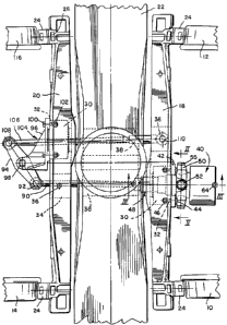
wheels 10/12 and 14/16 are secured to opposites ends of a respective axle, not
shown for sake of clarity, of a two-axle, four wheel railroad car truck. A
pair of
brake beams 18 and 20 extend crosswise of the car truck and parallel to each
other and to a truck bolster 22. Brake shoes 24 are mounted to the brake head
26 at each end of the brake beams 18 and 20. The brake beams 18 and 20 have
a generally U-shaped cross section. A non-pressurized head of a brake cylinder
or actuator 30 is integrally formed with each of the brake beams 18 and 20 and
' has a plurality of mounting holes 32 about the periphery thereof. The head
30
is to be referred to as an actuator aperture. The remainder of the actuator,
including the pressurized portion and piston, are mounted to head portion 30
by
fasteners through the apertures 32. On the other side of the center line of
each
of the brake beams 18 and 20 is a force transmitting aperture 34 for receiving
the
other end of the force transmitting elements. A pair of opposed mounting
holes 36 on the top and bottom portion of the flange are used to mount slack
adjusters in the apertures 34 or the end of a force transmitting arm of the
prior
art. The bolster 22 includes a pair of channels 38 on each side of the center
axis
and aligned with the opposed pair of actuator aperture 30 and the force
transmission aperture 34.
In a dual actuator, truck mounted brake, an actuator or brake cylinder is
mounted in each of the brake cylinder heads or actuator apertures 30 with a
force
transmitting element or pushrod extending through channels 38 in the bolster
22
and received in a slack adjusting element in aperture 34 of the opposed beam.
The present brake system includes a brake actuator or cylinder 40 mounted to
the
brake beam 18 at the actuator aperture 30 by a bracket 42 and an intermediate
cage 50. Bolts 44 extend through the elongated openings 43 (Figure 2) in the
bracket 42 and the mounting holes 32 in the brake beam 18 and are secured
thereto by nuts 46. A slack adjuster 48 extends from the cylinder 40 and lies
in
and extends through the actuator aperture 30 in the beam 18. The slack
adjuster
will be discussed in detail with respect to~~Figure 3.
CA 02131744 2000-08-22
-5-
The cage 50 mounts the actuator brake cylinder 40 to the brake beam 18
so that it freely rotates about two orthogonal axes to provide two axes of
adjustment about the center axis of the aperture 30 and may be considered a
gimbal. As illustrated in Figure 2, the cage SO is mounted to the bracket 42
by
fasteners 52 which are threadably received in aperture 41 of the bracket 42
and
extend into a sleeve bearing 54 in the cage 50. A non-pressurized cylinder
portion 58 is mounted to the cage 50 by a fastener 55 threadably received in a
bore 56 of the cage 50 and having an end extending into bearing sleeve 57 in
the
cylinder portion 58.
As illustrated in Figure 3, the brake cylinder actuator 40 includes a head
portion 60 which receives at one end the cylindrical portion 58 and includes a
piston 62 dividing the interior of head 60 into pressurized and unpressurized
volumes. A port 64 admits the fluid pressure to move the piston to the left to
operate the brakes. Spring 66 rests at one of its ends on the housing portion
58 and biases the piston 62 to the right or brake release position.
The slack adjuster 48 includes a back female clutch 70 at the piston 62, a
male clutch 72, a bearing 74 and a bearing cup 76. A compensator screw with
head clutch 78 is received in the front female clutch 74. Slack adjuster
spring 80
rests between the piston 62 and the bearing cup 76. A second slack adjuster
spring 82 rests between the actuator housing 58 and a flange on ram 84. A ram
spring 86 extends between ram 84 and a portion of the front female clutch
'14:. -
The slack adjuster 48 is a double acting slack adjuster integral with the
actuator
40 or brake cylinder.
A first force transmission element or rod 90 extends from the slack
adjuster 48 at ram portion 84 through the channel 38 in the bolster 22 and the
force transmitting aperture 34 in the second brake beam 20. The rod 90 is
connected at its other end by pin 92 to a first arm of transfer lever 94. A
pin 98
pivotally mounts the transfer lever 94 to a bracket 96 which is connected to
the
brake beam 20 by fasteners 100 extending through the mounting holes 32 and
nuts
102. The bracket 96 has an aperture 104, not shown, which aligns with the
2131744
-6-
actuator aperture 30 in the beam 20. A second force transmitting element or
rod
106 has its first end connected to a second arm of the transfer lever 94 by a
pin
108. The force transmitting rod 106 extends through the aligned aperture 104
in
bracket 96 and the aperture 30 in brake beam 20, through channel 38 in the
bolster 22 and into the force transmitting aperture 34 of the first brake beam
18.
A pin 110 extends through the pre-existing mounting hole 36 in the beam 18 to
connect the other end of the force element 106 to the first brake beam 18.
The cage 50 and its connection to the first brake beam 18 allows the
actuator 40 to freely maintain its axis of force application coaxial with the
axis of
the first force transmitting element or rod 90. This prevents twisting and
bending
of the piston 62 and possible damage to the slack adjuster 48 during the arc
movement of the force transmitting rod 90 as well as any non-parallelness of
the
brake beams 18 and 20 to each other. Although the bracket 42 has been shown
to be mounted to the preexisting mounting holes for a dual actuator beam
system,
it can be mounted to any brake beam.
Bracket 96 is configured such that it can be used with the preexisting
mounting holes 32 while positioning the attachment of the transfer lever 94 to
pivot about pin 98 at a center line midway between the axis of the opposed
pairs
of actuator apertures 30 and force transmitting apertures 36 in the brake
beams.
The aperture 104 in the bracket 96 allows the beam second force transmitting
element 106 to extend therethrough while allowing the use of the preexisting
mounting holes. While the bracket 96 has taken advantage of the preexisting
mounting holes 32 for the actuator opening 30 in the brake beam 20, it may
also
be used with other brake beams.
The method of assembly of the present brake system to the preexisting
brake beams 18 and 20 of a dual actuator system includes mounting bracket 42
to the first brake beam with the fasteners 44 and nuts 46 through holes 32.
The
brake actuator 40 with slack adjustor 48 can be previously mounted to the cage
SO which also can have been previously mounted to the bracket 42. While the
actuator 40 is external the actuator aperture 30, the slack adjuster 48
extends
CA 02131744 2000-08-22
_'J_
through the actuator aperture 30 in the beam 18. The previously connected
first
force actuating element 90 would extend through the opening 38 in the bolster
22
and the force transmitting aperture 34 in brake beam 20. Bracket 96 is mounted
to the second brake beam by fasteners 100 and nuts 102. The transfer lever 94
is
S mounted to the bracket 96 and the other end of the rod 90 is connected to
one
arm of the transfer lever 94. The second force transmitting element 106 is
extended through apertures 104 in the bracket 96 and aperture 30 in brake beam
20, through channel 38 in bolster 22 and into the aperture 34 in brake beam
18.
A first end of force transmitting element 106 is connected to the transfer
lever 94
and the other end is connected to the first brake beam 18 in the aperture 34.
Thus, a dual actuator, truck mounted brake can be converted to an
improved single actuator, truck mounted brake using the existing brake beams.
The reduced volume resulting from eliminating one fluid actuator is added to
the
actuator pipe to maintain the same cylinder pressure in an existing system.
Although the present invention has been described and illustrated in detail,
it is to be clearly understood that the same is by way of illustration and
example
only, and is not to be taken by way of limitation. The spirit and scope of the
present invention are to be limited only by the terms of the appended claims.