Note: Descriptions are shown in the official language in which they were submitted.
' , , ~131g58
TITLE OF INVENTION
Drainage or Weeping Port Closure for a Window Sill or the like.
~l~LD OF lNVENTION
This invention relates to devices for providing the drainage of
5 window sills, patio doors, or door sills.
BACKGROUND OF THE INVENTION
There exists at the present time a drainage port in most window
sill designs. Typically there are openings, located in the extrusions below
the tracks provided for movement of the windows or patio doors. These
10 openings in the extrusions are covered by a flap which has a pivot or pin
extending from each end, usually integral with the flap. The flap is
suspended adjacent to the opening and allows the water to exit the
extrusion. However generally the flap will extend and hang by gravity at
90 degrees to the horizontal, substantially extending with the vertical
15 part or portion of the sill. Therefore gravity offers no assistance to
closing the flap whatsoever. In fact if the water adjacent the opening
freezes the flap may be kept open by the ice accumulated and may
become an inlet for cold air thus reducing the effectiveness of the sill as
a thermal barrier. If the sill includes an angled face containing the
2 0 opening to be closed, the flap will still extend at 90 degrees to the
horizontal and leave the angled opening uncovered.
For example if the extrusion is made from vinyl and is for a double
hung window typically there is a track provided with the sill for each
window and there is a slanted bottom provided on the sill extrusion
2 5 which slants toward the opening from each track. There is an inner
track and outer track provided, the inner track draining to the outer
track and the outer track draining to outside. The outer track wall
contains the flap which pivots. If ice accumulates around the flap then
in fact the cold air will move from the outer track to the inner track
3 0 around the window and into the home or space being closed by the
- 2 - 2131958
~window. This is compounded if the outer track wall is angled to the
horizontal as discussed above.
It will therefore be advantageous to provide a closure for a
drainage port or a weeping port which is assisted by gravity to a closed
5 position, and further which readily closes openings provided in
extrusions which have angled surface to the horizontal and vertical.
It will also be advantageous to provide a drainage port for a sill
which drains the inner chamber of an extrusion and the outer track of
an extrusion, the inner track draining internally to the inner chamber.
It is therefore an object of this invention to meet the
aforementioned objectives simply and economically.
Further and other objects of the invention will become apparent to
those skilled in the art when considering the following summary of the
invention and the more detailed description of the preferred
15 embodiment illustrated herein.
SUMMARY OF THE INVENTION
According to a primary aspect of the invention there is provided a
drainage port closure for a sill portion of a closure assembly, the
drainage port closure closing a drainage port provided in the sill of a
2 0 closure assembly and comprising a preferred snap in member having
means for providing the closure member for the drainage port therein,
preferably said means being raised outwardly away from a preferably
substantially rectangular member which clips in position within the
drainage port and has further provided there with means for suspending
2 5 a flap at an angle to the horizontal so as to be assisted by gravity to a
closed position, the flap being suspended from said means, the flap
including pin portions extending laterally away from the ends thereof to
suspend from the means for suspending the pivots, further said
preferred substantially rectangular portion including a hood or a cover
3 0 portion for covering the opening in part from the environment and
3 21 3 1 ~58
extending laterally away from the rectangular portion on the side
opposite of the rectangular portion from which the flap is suspended,
the closure assembly preferably snap fitting into said drainage port and
providing gravity assisted closure for said drainage port.
According to yet another aspect of the invention there is provided
a drainage port closure for a window sill, said window sill including
drainage extending from said outer track and said inner chamber, said
drainage port closure including a preferred substantially rectangular
member having two ends and two sides, a top and bottom, and having
disposed proximate one side thereof proximate the top thereof, a
laterally extending flange having disposed proximate the ends thereof
and the end of the said port closure a pivot support for receiving the
pivot disposed with the flap provided with the assembly, the pivot
support will dispose the flap at substantially an angle to the horizontal
and vertical planes with in which a window is disposed, (and preferably
45 degrees) said rectangular member having disposed proximate the
other side thereof a hood assembly for hooding the opening open by the
said flap, wherein when water is drained from said outer track or said
inner chamber, said flap is assisted back to a closed position by gravity
2 0 unless water is draining from said flap which will pivot away from said
housing and assist the water to pass outwardly away from said inner
track and said inner chamber. According to a preferred embodiment of
the invention said extrusion is made from vinyl and said preferably snap
in drainage port assembly for said port of said sill is made from
2 5 thermoplastic material or thermoset material.
The drainage port closure described in the two paragraphs above
may fit into an opening provided in a vertical extrusion wall or one
angled to the vertical such as those openings provide in overhung
surfaces . Therefore the drainage port closure may be disposed with an
3 0 overhung or angled extrusion wall.
- 4 - Z13~L958
BRIEF DESCRIPIION OF THF. DRAWINGS
Figure 1 is a perspective view of the drainage port closure member
illustrated in one embodiment of the invention.
Figure la is a perspective view of the drainage port closure member
5 illustrated in another embodiment of the invention.
Figure 2 is a schematic view of the flap included with the drainage
port closure member of figures 1 or 1 a.
Figure 3a. b. c. are front, top, side, and cut away views of figure 1 a
illustrated in a preferred embodiment of the invention.
10 Figure 4a. b. c, are similar views in relation to figures 3, a, b, c, but
with respect to figure 1 and illustrated in the preferred embodiment of
the invention.
Figure 5 is a sectional view of an extrusion including two drainage
port closure member and illustrated in a preferred embodiment of the
1 5 invention
DETAlLED DESCRIPIION OF THE DRAWINGS
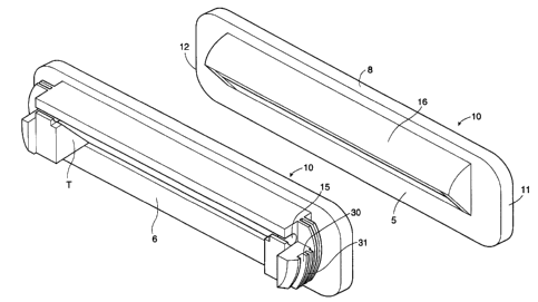
Referring generally to the figures there is provided a substantial
rectangular closure for a drainage port (10) having two ends (11) and (12)
and two sides (5) and (6) and a top (8). Said closure for the drainage port
20 having disposed on one side (6) openings (15) for suspending a flap (20) as
best seen in figure 2 and specifically the pivots thereof (21 ) which fit withinthe openings (15) and which allow the flap to be closed by gravity at a
substantial angle to the horizontal and vertical as suspended adjacent
opening ( 15) and assisted by gravity . Fastening portions (30) are serrated
2 5 at (31 ) to clip within the opening of the substantially rectangular drainage
port as best seen in figure 5 of the window sill W. Located on side (8) of
said closure for a drainage port (10) is a hood (16) which closes or hoods
over the flap to protect from the elements. Similarly with respect to figure
1 a it is provided that all the elements of figure 1 are present with the
3 0 exception that the fasteners (40) and serration (41 ) are separated from
~ 2~1958
- 5 -
portion (6a) and suspended near opening (15). As best seen in figure 2 said
flap (20) closing the opening is pivoted by pins (21 ) and is suspended near
the opening.
Referring to figures 3, 3a, b, c 4, 4a, b, c, there is illustrated said
5 closure member 10 having disposed therewith said opening (15) and a
butting surface T disposed substantially at an angle of 45 degrees. Said
flap of figure 2 will but against said surface T when in a closed position
and will allow water to past from said closure port opening as water
presses against the flap.
As can be seen figure 3a and 4a the member 10 at each side thereof
has the hood 16 and flap suspension assembly 6a with the supporting
surface T disposed therewith at an angle of 45 degrees.
Referring to figure 5 there is illustrated a sill W including an inner
track T 1 and an outer track T2. The track portions are formed by
15 extrusion portions E 1 and E2 respectively which include drainage
openings Il and I2 which drain any liquid collecting in the tracks or
outer chamber Cl to the closure members lOa and lOb.
The closure members lOa and lOb are illustrated as installed in a
vertical extrusion wall E4 and an overhung or angled wall E3. The
2 0 closure will work well in both situations so long as the flap is assisted by gravity to the closed position. Should the overhang portion E3 be
extreme so as to dispose the flap of the illustrated embodiments at an
angle of greater than or equal to 90 degrees than the embodiment must
be redesigned for that particular situation to ensure that the flap
2 5 properly closes.
As many changes can be made to the preferred embodiments of
the invention without departing from the scope thereof; it is asserted
that all matter contained herein can be consider illustrative of the
invention and not in a limiting sense for the invention.