Note: Descriptions are shown in the official language in which they were submitted.
CA 02131971 1998-02-2~
rlOTOR CONTROL SYSTEM AND APPARATUS ~FOR PROVIDING
DESIRED THREE-P~ASE VOLTAGE THEREIN USING A ~IN
TRANSFORMER ENERGIZED THROUGH AN AUTO TRANSFORMER
Backqround of the Invention
This invention relates generally to a motor control system
and an apparatus for providing a desired three-phase voltage in
the motor control system. In a particular aspect, the invention
relates to such a system and apparatus adapted to operate from
a higher voltage primary source while still using industry
standard lower voltage components. In another particular aspect,
the invention relates to such a system and apparatus adapted to
operate from a lower voltage primary source that is stepped up
- with a corresponding step down in current. The system and
apparatus can be used in operating a three-phase motor to drive
a submersible pump, for example.
Submersible pumps are used, for example, in oil wells at
remote locations. Three-phase electric motors are typically used
to drive these pumps. Such a motor is rated for a nominal line-
to-line voltage which must be provided within a specified
tolerance for the motor to work. This voltage is typically
provided from an electric utility through a transformer and motor
controller to provide the suitable voltage and control to operate
the motor as desired. A motor control system and components of
the system are disclosed in United States Patent No. 5,130,616
to Owen.
A specific implementation of such a system is typically made
for use with a specific nominal input voltage. For the exemplary
system disclosed in the Owen patent, a specific implementation
is preferably energized by a nominal alternating current (a.c.)
25 kilovolt (kV) (25,000 volts) line-to-line three-phase voltage.
This is a conventional utility voltage in many countries, and
accordingly many of the components of the particular
implementation are not designed to operate at higher voltage
levels. If a higher nominal input voltage were to be
accommodated, more expensive and less readily available
components would preferably be needed. For example, for a
nominal 25 kVac voltage, components preferably have a 150 kV BIL
--2-- X! ~. e,J
(basic impulse insulation level) rating as Xnown in the industry.
Components at this rating are readily available and relatively
inexpensive; however, higher BIL rated components that would
preferably be used at a higher voltage (e.g., 33 kVac) are not
as readily available and are more expensive.
Although the aforementioned nominal 25 kVac source is
standard in many countries, a higher voltage source is used in
many important oil producing countries where submersible pumps
are needed. For example, in several Middle Eastern countries the
standard utility power source is at 33 kVac. If the invention
of the aforementioned Owen patent were to be used with such a
power source, a specific implementation different from the 25-
kVac implementation would be needed. That is, although the
invention could be used, it wouId have to be implemented with
higher rated components than an implementation limited to a
maximum nominal input voltage of 25 kVac.
To avoid having to design a different overall
implementation, construct such implementation with more costly
components, and maintain multiple inventories, there is the need
for an improved motor control system and apparatus for such
system whereby a lower voltage implementation can be more simply
modified for use with a higher voltage input power source.
There are also situations where maximum current into a
primary of a transformer providing the desired voltage for the
motor is a significant concern. Rather than redesigning the
primary to accommodate a larger current in such a case, it may
be preferable for economic reasons or otherwise, to step up a
lower voltage power source to a higher voltage but lower current
than is drawn by the motor at the lower voltage output by the
transformer. The stepped-up higher voltage would preferably be
the rated nominal input voltage of the transformer necessary to
obtain the desired output voltage for the motor, and the lower
current would preferably not exceed the rating of the primary of
the transformer at such nominal input voltage. To provide for
this, there is the need for an improved motor control system and
apparatus for such system whereby a current-limited
.'
2 ~ 3 ~
implementation can be accommodated without replacing the current-
limited feature.
8ummary of the Invention
The present invention overcomes the above-noted and other
shortcomings of the prior art and meets the aforementioned need
by providing a novel and improved motor control system and
apparatus for providing a desired three-phase voltage in the
motor control system.
In meeting the aforementioned need, a preferred embodiment
of the present invention lowers the continuous voltage applied
to a disconnect switch, fuses and the primary of a main
transformer of the motor control system. This allows, for
example, industry standard (150 kV BIL) switches and fuse holders
for a 25 kVac system to be used even when the input voltage is
higher (e.g., 33 kVac). This preferred embodiment also forces
transients that enter the input terminals to pass through
impedances 80 that the transients are attenuated before they
reach the disconnect switch, the fuses and the main transformer
primary. This again allows the lower rated components to be used
in the higher rated system.
The preferred embodiment can also limit the -~i fault
current that can flow through the internal primary fuses. This
allows limited interrupting capacity fuses to be used, again
providing for reduced cost in accommodating a higher voltage
power source.
The preferred embodiment can be implemented so that
ferroresonance is prevented.
Another preferred embodiment allows a current-limited
primary of a transformer to be used even when the motor draws
from the secondary of the transformer a current that exceeds the
current limit of the primary.
In one embodiment, an apparatus for providing a desired
three-phase voltage in a motor control system in accordance with
the present invention comprises: a compartment having an
insulating fluid therein; a first step-down transformer disposed
in the compartment, which first step-down transformer includes
three-phase primary winding means for receiving a maximum rated
--4--
three-phase voltage and further includes three-phase secondary
winding means for providing a desired three-phase voltage in
response to the maximum rated three-phase voltage applied to the
primary winding means; a second step-down transformer disposed
in the compartment for receiving from an electrical energy source
an input three-phase voltage that is greater than the maximum
rated three-phase voltage and for providing an output three-phase
voltage that is not greater than the maximum rated three-phase
voltage; and connector means disposed in the compartment for
connecting the first and second step-down transformers, which
connector means includes switch means and fuse means connected
to the first and second step-down transformers.
In another embodiment, an apparatus for providing a desired
three-phase voltage in a motor control system comprises: a
compartment having an insulating fluid therein; a step-down
transformer disposed in the compartment, which step-down
transformer includes three-phase primary winding means for
receiving a maximum rated three-phase current and further
includes three-phase secondary winding means for providing a
desired three-phase voltage in response to a rated three-phase
voltage applied to the primary winding means; a step-up
transformer disposed in the compartment for receiving from an
electrical energy source an input three-phase voltage that is
less than the rated three-phase voltage and for providing an
output three-phase voltage equal to the rated three-phase voltage
at a current not greater than the ~; rated three-phase
current; and connector means disposed in the compartment for
connecting the step-down and step-up transformers, which
connector means includes switch means and fuse means connected
to the step-down and step-up transformers.
In particular implementations, the second step-down
transformer of the first-mentioned embodiment and the step-up
transformer of the second-mentioned embodiment each includes a
three-phase autotransformer having a neutral grounded internally
within the compartment. More preferably, the three-phase
autotransformer includes three single-phase wye-connected
autotransformers connected to the switch means.
~ ' ~
L ,~ C~
-5-
The present invention also provides a motor control system
that includes such an apparatus. In general, such a system
comprises: load connection output terminals for connecting to
an external motor; first transformer means for conducting
electric power consumed by the motor control system and the
external motor, which first transformer means includes: a
primary winding rated to receive a rated voltage, wherein the
rated voltage is a selected alternating current voltage within
the range of about 20 kilovolts (a.c.) to about 35 kilovolts
(a.c.); and a secondary winding adapted to supply power directly
to the external motor via the load connection output terminals;
a motor controller for switchably connecting the secondary
winding to the load connection output terminals, which motor
controller includes switch terminals connected to the secondary
winding and the load connection output terminals; power
connection input terminals for connecting to an external electric
power source providing alternating current voltage of at least
about 20 kilovolts (a.c.) but different from the rated voltage
of the primary winding; second transformer means, connected to
the power connection input terminals and the primary winding of
the first transformer means, for converting voltage from the
external electric power source to the rated voltage for the
primary winding of the first transformer means; and a single
transportable containment means for holding the power connection
input terminals, the load connection output terminals, the first
and second transformer means and the motor controller.
Therefore, from the foregoing, it is a general object of the
present invention to provide a novel and improved motor control
system and apparatus for providing a desired three-phase voltage
in the motor control system. Other and further objects, features
and advantages of the present invention will be readily apparent
to those skilled in the art when the following description of the
preferred embodiments is read in conjunction with the
accompanying drawings.
,~,
..
CA 02131971 1998-02-2~
Brief Description of the Drawinq
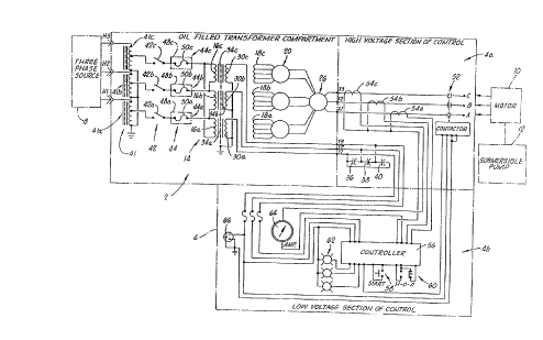
FIG. 1 is a schematic circuit diagram of a preferred
embodiment motor control system and apparatus of the present
invention.
FIG. 2 is a schematic diagram of the windings of a step-
up autotransformer for another preferred embodiment of the
present invention.
Detailed Description of Preferred Embodiments
A preferred embodiment of the motor control system and
apparatus of the present invention is schematically shown in
FIG. 1. The apparatus is embodied in a transformer circuit
2 which is used within the overall motor control system that
also includes a motor controller circuit comprising a high
voltage section 4a and a low voltage section 4b. These are
enclosed within a transportable containment apparatus
represented by dot-dash line 6.
The input of the transformer circuit 2 is adapted to be
connected to a suitable power source, such as a three-phase
electric utility power source 8. For the embodiment of FIG.1,
the source 8 typically provides a nominal line-to-line
voltage higher than the tolerable line-to-line voltage of a
load to be energized with the present invention. For the
preferred embodiments described herein, the power source 8
provides a substantially constant a.c. voltage from within
the range of about 4160 Vac to about 34500 Vac or above
("substantially constant" encompassing fluctuations from the
nominal voltage in a conventional voltage source). The lower
limit is more preferably about 20000 Vac because this is
where BIL ratings begin for components used in a motor
control system of the type to which the present invention is
directed. In a specific implementation of the FIG.1
embodiment, the voltage is nominally 33000 (33 kVac). This is
the input voltage to the transformer circuit 2. The FIG 2
embodiment of the present invention lowers this voltage and
controls its application to the...
-7-
load, such as a three-phase motor 10 connected to a submersible
pump 12. The windings of the motor 10 are connected to outputs
A, B, C, of the high voltage section 4a of the motor controller
for the use illustrated in FIG. 1.
In a contemplated particular application, the motor control
system would be placed at the base of a typical riser pole which
supports the three-phase power lines of the utility power source
8. Cables from the source 8 would be run down the riser pole and
connected to inputs H1, H2, H3 of the transformer circuit 2.
From the outputs A, B, C of the high voltage section 4a, cables
would be extended to a vented junction box from which cables
would extend to connect to the motor 10.
Referring to FIG. 1, the transformer circuit 2 includes a
main transformer 14. The main transformer 14, which is a step-
down transformer in the illustrated embodiment, includes three
primary windings 16a, 16b, 16c, and three secondary windings 18a,
18b, 18c. The windings 16, 18 are conventional. The secondary
windings 18 are switchably interconnected by a suitable output
selection switch 20, such as one used in transformers
manufactured by Southwest Electric Company of Oklahoma City. In
a particular embodiment, the switch 20 has two exterior handles
mounted on shafts passing through the containment apparatus 6.
Rotating the handles selects different taps from the windings 18
for providing different outputs. The handles are manually
operated by a person standing on the ground adjacent the motor
control apparatus. The switch 20 of the preferred embodiment
provides a wide voltage range with all outputs being full kVA
rated. The secondary of the transformer 14 is dedicated to a
single load, namely the electrical submersible pump motor 10 in
the preferred embodiment.
The thus selected portions of the windings 18 are then
connected in either a delta or a wye connection by means of a
switch 26 which has a handle mounted on a shaft of the switch 26
passing through the containment apparatus 6. An example of a
suitable switch 26 is the RTE Components (Pewaukee, Wis.) lSOA
externally operated Series Multiple Switch.
~: .:. ,
' ' ', ~
~ . ~
~ ~ 3 ~ r~
-8-
Transformer 14 also includes tertiary windings 30a, 30b, 1;
30c. The primary windings 16, the secondary windings 18 and the
tertiary windings 30 are all inductively coupled within
respective groups to provide a three-phase transformer. Each
phase of the preferred embodiment is wound wherein a core leg
supports the secondary winding 18a, the tertiary winding 30a and
the primary winding 16a. Preferably, these windings are in a
configuration with the tertiary winding 30a radially in between
the primary winding 16a and the secondary winding 18a. A
conventional electrostatic shield 34a is disposed between the
primary winding 16a and the tertiary winding 30a. Whether the
~econdary is innermost and the primary outermost or vice versa
i8 immaterial; what is preferred is that the tertiary is radially
in between the two and that the electrostatic shield 34 (if used)
is radially in between the tertiary and the primary. These same
relationships for the tertiary and electrostatic shield should
be retained if additional radially disposed windings are used
within a winding group on a core leg. Each of the other two
phases is similarly constructed. The core legs in the preferred
embodiment are part of an overall iron core of a type known in
the art.
The tertiary windings 30 provide electrostatic shielding so
that the transformer 14 is double-shielded. This is achieved by
grounding one end of each of the windings 30a, 30b, 30c as shown
2S in FIG. 1 (alternatively, one tertiary winding could be grounded
and the other tertiary windings could be connected to the
grounded winding, or to both ground and the grounded winding).
This places these common ends in a common ground connection with
the conventional electrostatic shield 34. ~hus, both the
electrostatic shield 34 and the tertiary windings 30 filter
electrostatically induced transients; therefore, they need to be
disposed between the primary and secondary windings. So that ;
each tertiary 30 can itself be shielded, the respective
electrostatic shield 34 needs to be between the primary and the
tertiary. A different degree of electrostatic shielding can be
obtained by the tertiary windings 30 depending upon the
particular winding configuration and axial length. In general,
.....
:.
I
!- ~ ~ . .~j -:. ~j, ., ., . ! ,
r2 ~ L '
g
these should be such that the electrostatic induction between the
primary windings 16 and the secondary windings 18 is measurably
reduced. To maximize the shielding, the axial length of each
tertiary winding should be at least as long as the longer of the
respective primary winding or secondary winding.
The tertiary windings 30 also filter magnetically induced
transients in conjunction with capacitors 36, 38, 40 physically
located within the high voltage section 4a of the motor
controller but electrically connected to the tertiary windings
30. The capacitors 36, 38, 40 shown in FI&. 1 are connected to
the ends of the tertiary windings 30 opposite the ends thereof
connected to electrical ground. The capacitance preferably is
such that the magnitude of transient voltages induced into the
tertiary and secondary windings by lightning or switching spikes
imposed onto the primary windings is measurably reduced.
A third function of the tertiary windings 30 is to provide
control power and metering voltages in the controller section.
This is illustrated in FIG. 1 by the connections of the tertiary
windings 30 to the low voltage section 4b of the motor control
circuit.
In a particular implementation, each of the tertiary
windings 30 is implemented by a respective layer of a 3/16 inch
wide by 1/16 inch thick rectangular wire spirally wound on the
re~pective electrostatic shield 34 with 3/16 inch spacing between
turns. Within each phase of the transformer 14, each of the
respective windings and the electrostatic shield is electrically
insulated by being wrapped on kraft paper or other suitable
insulating substrate known in the art.
The transformer circuit 2 also includes a primary winding
aircuit which connects the primary windings 16 to the power
source 8 when the power source is connected to the high voltage
terminals Hl, H2, H3.
The primary winding circuit of the FIG. 1 I- ho~i -nt
includes a step-down input transformer 41 for receiving from the
electrical energy source 8 an input three-phase voltage that is
greater than a maximum three-phase voltage for which the primary
windings 16 of the transformer 14 are rated. The input
' ',
CA 02131971 1998-02-2
-10-
transformer 41 converts this input voltage to provide an
output three-phase voltage that is not greater than such
maximum rated three-phase voltage so that the main
transformer 14 is adapted by the input transformer 41 for use
with the power source 8 when such power source provides
voltage above the maximum rating of the transformer 14.
Thus, when the main transformer 14 is of a type that converts
a line-to-line voltage of a first three-phase power source
(e.g., one providing nominally 25 kVac) to a level compatible
with the nominal line-to-line voltage rating of the motor 10,
the input transformer 41 converts a line-to-line voltage of
a second three-phase power source (e.g., one providing
nominally 33 kVac) to a level equivalent to the line-to-line
voltage of the first three-phase power source thereby
enabling conventional lower voltage components to be used on
the primary side of the transformer 14 even though there is
a higher input voltage. Preferably, the primary windings 16
are rated to receive a rated voltage that is a selected
alternating current voltage within the range of about 20 kVac
to about 35 kVac. This selection is made preferably in
response at least in part to a desired BIL rating for a
primary switch and fuses preferably to be used as
subsequently described.
Although any suitable transformer can be used for the
input transformer 41, a three-phase autotransformer having a
neutral grounded internally within the compartment of the
system is preferred. More preferably, the transformer 41
includes three single-phase wye-connected autotransformers
41a, 41b, 41c connected respectively to the high voltage
inputs H1, H2, H3 and to respective terminals of a primary
switch 42 as illustrated in FIG.1. It is through the primary
switch 42 that the output terminals of the auto transformers
41 are connected to respective nodes of the delta-connected
primary winding 16 as shown in FIG.1. Three single-phase
transformers are more effective at reducing or preventing
ferroresonance than one three-phase transformer having a
four- or five-legged core design. Autotransformers are
CA 02131971 1998-02-2
-lOa-
preferred because they have lower leakage reactances, lower
losses, smaller exciting current and lower cost than two-
winding transformers when the voltage ratio does not differ
too greatly from 1:1.
The primary switch 42 to which the input transformer 41
is connected is used for selectably energizing and de-
energizing the...
rJ ~
--11-- ~,
main transformer 14 and the motor controller from the power ~ ;
source 8. The switch 42 of the preferred embodiment is intended
to be operated manually by a person standing on the ground
adjacent where the motor control system is located. This
5 operation is direct, i.e., without the aid of any tools, such as
a hot stick. The switch 42 should be rated at least for
interrupting full load current. The switch 42 is a true
emergency safety disconnect switch which can be directly operated
by a person to break the current conductive path between a
connected power source and the primary windings 16. When the C
switch 42 makes or completes the current conductive path, the
a.c. voltage from the secondary of the transformer 41 is applied
to the primary windings 16 so that an induced a.c. output voltage
is provided on the secondary windings 18. This causes an output
current to flow in a secondary winding circuit connected to the
secondary windings 18 if the secondary winding circuit is
completed as subsequently described. The resulting current which
flows through the primary side of the main transformer 14 is
proportional to such output current. The switch 42 is preferably
one which is oil-insulated so that it is relatively inexpensive
despite being able to break full load current. Any suitable type
switch can be used, such as a RTE Components two-position
Loadbreak/Loadmake stored energy type switch. This is a three-
phase switch with one pole per phase connected in series between
the respective component of the input transformer 41 and a
respective primary winding 16 of the main transformer 14. The
operating mechanism of the switch 42 includes a shaft which
extends through the containment apparatus 6. This pass-through
of the containment apparatus 6 and the others referred to herein
are made fluid-tight by suitable sealing members as would be
readily known in the art.
Connected in series with the respective section of the
switch 42 are load sensing fuses 44a, 44b, 44c. The switch 42
and the fuse 44 can be in either order within the series
configuration between the two transformers 14, 41.
The fuses 44 are preferably field replaceable, such as by
being contained within draw-out mechanisms that penetrate the
"
.
-12-
side of the containment apparatus 6. Each fuse 44 includes a
fuse carrier 48 having terminals connected in the electrical
series as represented in FIG. 1. The fuse carrier 48 is also
connected to the containment apparatus 6 so that an opening of
the fuse carrier communicates outside the containment apparatus
6. A fuse ~ h~r 50 is releasably connected within the fuse
carrier 48 and is replaceable through the opening of the fuse
carrier 48. A particular type of fuse which can be used is the
RTE Components Bay-O-Net Fuse Assembly with the RTE Components
Dual Sensing Bay-O-Net Fuse Link.
The fuses 44 are relatively inexpensive because they provide
a lower current interrupting capacity. The fuses 44 are capable
of interrupting a fault current with a magnitude limited solely
by the sum of the internal impedance of the power source 8 added
to the impedance of the transformer 41 with a short circuit
anywhere downstream from the transformer 41. Stated another way,
the fuses 44 stop current flow within the primary winding circuit
in response to current flowing therethrough exceeding a
predetermined level in response to a short-circuit fault anywhere
downstream from the transformer 41. For example, when a short-
circuit fault on the secondary side of the transformer 14 occurs,
the magnitude of the output current increases and the magnitude
of the input current increases in response. When the increase
of the input current reaches a predetermined level, the fuses 44
clear. The predetermined level corresponds to the selected
rating of the fuses 44. When the fuses clear, the main
transformer 14 and the secondary winding circuit are de-
energized. This protects the portion of the system upstream of
the fault (towards the power source).
Although not shown in the drawing, the transformer circuit
can also include suitable conventional arresters to shunt each
line to ground in a conventional manner.
The motor controller components of the motor control
sections 4a, 4b are conventional. Typically, the particular
motor controller would be specified by the user to coordinate
with other equipment. An example of a typical controller is a
Keltronics brand motor controller.
. .
'? ~ 3 ~ ~ rl ~-
-13-
Referring to FIG. 1, the high voltage section 4a includes
a vacuum contactor 52 which is electrically operable to connect
or disconnect the outputs from the switch 26 to the terminals A,
B, C (and the motor 10 when connected thereto)~ The outputs from
the switch 26 are provided to the high voltage section 4a through
terminals Xl, X2, X3. In the prefer-ed embodiment the output
includes a substantially constant a.c. voltage within the range
of about 460 Vac to about 4160 Vac. There is one contactor pole
per phase in series between the secondary of the main transformer
14 and the output terminals A, B, C. The contactor 52 is an
electrically operated start-stop switch which turns a motor
connected to the terminals A, B, C on or off when the output
voltage is available at the contactor poles connected to the
selected secondary winding sections through the switches 20, 26
and the terminals X1, X2, X3. These connected components
comprise the secondary winding circuit by which the motor 10 is
connected to the secondary of the transformer 14. The wiring,
such as cables, used to connect the motor 10 to the terminals can
also be part of the secondary winding circuit. When the
contactor 52 is in a conductive state, and the motor 10 is
connected, the entire secondary circuit is completed so that if
there is output voltage it is applied to the motor and ouL~uL
current flows through the secondary windings, the secondary
winding circuit and the motor (when reference is made to a
voltage being applied or the like from one point to another, this
encompasses any voltage drops across intervening circuitry).
When the contractor 52 is in a non-conductive state, the motor
10 is not energized.
The high voltage section 4a also includes three current
transformers 54a, 54b, 54c which sense current through the
respeative phase output line to provide control signals to a
solid state logic controller 56 in the low voltage section 4b.
The controller 56 also receives sensing inputs, as well as
energizing electricity, from the tertiary windings 30. The
controller 56 is operated by start and h-o-a (hand-off-automatic)
switches 58, 60, respectively. Indicator lights 62 signal
operating conditions in a known manner. A chart recorder/ammeter
~'
64 is also included in the low voltage section 4b, as is a
convenience outlet 66.
The transportable containment apparatus 6 of the preferred
embodiment includes a single, multicompartment enclosure mounted
on a skid. The skid provides a base for supporting the housing
on the ground. The containment apparatus 6 can be positioned
before or after the external connection cables have been
installed at the site where the present invention is to be used.
The multicompartment enclosure includes a compartment for
receiving the components of the transformer circuit 2 shown in
FIG. 1. These include the transformer 14 (except for the
capacitors 36, 38, 40), the transformer 41, the primary switch
42 and the fuses 44. In the preferred embodiment these
components are immersed within a volume of insulating fluid, such
as a suitable oil known in the art. The surface of the fluid is
below the access openings of the fuse carriers 48 of the field
replaceable fuses 44. The portion of each fuse carrier 48 into
which its replaceable fuse element 50 is connected is, however,
below the surface of the fluid, as are the other components of
the transformer circuit 2 which are within the compartment.
The enclosure includes another compartment in which the
capacitors 36, 38, 40 and the components of the motor control
sections 4a, 4b are located. At one end of this compartment
there is an outer door. There is an inner door located within
the interior of this compartment to divide it into two chambers.
The components of the low voltage section 4b shown in FIG. 1 are
located in the outer chamber and on the outer door, and the
capacitors 36, 38, 40 and the components of the high voltage
section 4a shown in FIG. 1 are located within the inner chamber.
The enclosure includes a further compartment containing the
high voltage terminals H1, H2, H3 (FIG. 1) to which the power
source ~ connects. A door is connected at one end of this
compartment.
In use, the motor control system of the present invention
is transported to a location where it is to be connected to a
power source and a load, such as the power source 8 and the motor
lO and submersible pump 12 combination. Transportation to and
d J
-15-
placement at the location are facilitated by the single
containment housing 6 which has all the electrical components
located and interconnected therein.
Once at the location, conventional power connections are
made to the high voltage terminals H1, H2, H3, and conventional
load connections are made to the terminals A, B, C in the high
voltage section 4a. Operation then proceeds as described in the
United States Patents to Owen incorporated herein by reference,
except that the transformer 41 converts the voltage input from
the source 8 to the level for which the transformer 14 is rated.
Another preferred embodiment of the present invention
includes an input transformer 141 having the winding arrangement
shown in FIG. 2. The transformer 141 is used in place of the
transformer 41 shown in FI~. 1, and it is so used when the
primary windings 16 of the main transformer 14 are rated to a
maximum three-phase current that is to be accommodated by using
a power source 8 that provides an alternating current voltage
which is less that the selected rated input voltage for the main
transformer 14. The input transformer 141 steps up the voltage
~rom the power source 8 to the rated input voltage for the main
transformer 14 while stepping down the current so that the
maximum current from the transformer 141 at the rated voltage of
the primary windings 16 of the main transformer 14 is not greater
than the maximum rated current of the primary windings 16. A
non-limiting example is as follows:
main transformer 14 maximum input voltage rating 8320 V
main transformer 14 maximum input current rating 150 A
power source 8 nominal voltage 4160 V
input transformer 141 output voltage8320 V
input transformer 141 maximum output current at
said output voltage 150 A
If the load current drawn from the secondary windings 18 of the
main transformer 14 requires current exceeding the ~ m rated
current of the primary windings 16, then this overloads the
system and either pulls the input voltage down or clears the
fuses 44.
,:
.
I -16-
The other aspects described above with regard to the FIG.
1 embodiment apply to the preferred embodiment using the
transformer 141. Thus, the transformer 141 is also preferably
an autotransformer (except configured for stepping up voltage)
as described above.
Thus, the present invention is well adapted to carry out the
objects and attain the ends and advantages mentioned above as
well as those inherent therein. While preferred embodiments of
the invention have been described for the purpose of this
disclosure,
:".
changes in the construction and arrangement of parts can be made
by those skilled in the art, which changes are encompassed within
the spirit of this invention as defined by the appended claims.
':
~ ,~
. . ,
~ .
.;