Note: Descriptions are shown in the official language in which they were submitted.
~~ 213204fi
1
ERGONOMIC SHOVEL
BACKGROUND OF THE INVENTION
a) Field of the Invention
The present invention relates to a hand tool for the
shovelling of debris, particularly snow and ice, having a
flexible portion along its handle so as to permit limited
flexion of the handle when lifting a load.
The invention also relates to a hand tool as described
above, where the handle is collapsible or retractable.
b) Description of prior art
Hitherto, it has been common to mount a blade on a handle
to form a tool which may be used for shovelling.
United States Patents NOS. 1,177,072, 1,177,073, 1,267,915,
1,930,000, 2,047,485, 3,401,971 relate to shovels which
have collapsible or retractable handles of various designs.
United States Patent 4,730,860 relates to a shovel having
a vibrator mounted between the handle and the blade so as
to increase its digging efficiency.
United States Patent 4,691,954 relates to a snow shovel
having a telescoping handle and a detachable blade. A
compression spring extends lengthwise within the handle.
This spring is mounted so as to compress under load or
shock from striking an object submerged in the snow. When
the shovel is lifted, the spring decompresses and assists
in discharging the load.
:. ~ ~ 213~o~s
2
In the snow remover art, United States Patent 4,550,943
relates to a snow remover with a collapsible handle.
In the broom art, United States Patent 645,988 relates to
a handle which has a slit lengthwise along it whereby the
handle absorbs the initial shock when sweeping.
It is recognized that one of the problems associated with
such devices is that they are associated with back pains
due to the stiffness of the handle. Indeed, because of
such stiffness, the user of the shovel has to absorb all
the force fluctuations associated with lifting a load and
discharging it. Particularly, when the user lifts a load
with a given force and this load is greater than
anticipated, he or she does not have the opportunity to
adjust to the new load gradually and thus risks injury when
lifting a load of unknown weight.
OBJECTS OF THE INVENTION
It is apparent from the foregoing that it is desirable to
have a shovel where a portion of the handle can flex in a
limited manner in a plane perpendicular to the front edge
of the shovel exclusively, such that the handle absorbs
part of the initial shock and permits the user to gradually
adjust the force required to lift the load.
An object of the present invention is to provide such a
hand tool having a flexible portion to help prevent the
risk of injury. Another object of the invention is also to
provide a shovel of the above mentioned type which has a
telescopic handle to permit easy and compact storage.
:. ' 2132046
3
SUMMARY OF THE INVENTION
In meeting this and other objects, the present invention
provides a shovel comprising:
- a blade having a front edge and a rear portion;
- a handle having a front surface and a back surface and
two opposite ends, one the ends being fastened to the
rear portion of the blade, where the handle has a
portion adjacent to the blade which is made flexible
so as to permit flexion of the handle to a given
extent exclusively in a plane perpendicular to the
front edge of the blade.
In use, when a user lifts a load with a given force and the
load is greater than anticipated, the flexible portion will
permit the user to adjust the force required to lift the
load, thereby permitting the user to adjust smoothly to a
new load and help prevent the risk of injury when lifting
a load of unknown weight.
Furthermore, the flexible portion aids in discharging the
load by providing a catapult-like effect when it resumes
its static position.
The flexible portion of the handle may consists of either
a hollow piece of resilient plastic material having fins
extending longitudinally along its side, or of a piece of
resilient plastic material having recesses opening on the
back surface of the handle and in which are inserted pieces
of elastomer. A slidable sleeve may be mounted over such
piece and the handle so that the user can adjust the amount
of resiliency of the flexible portion.
Furthermore, the handle can be made telescopic and thus
comprise an extendable portion that can be either retracted
:. ' 2132046
4
inside the main portion of the handle or fastened in an
extended position. Advantageously, the handle can also be
designed so as to be retracted through an opening provided
in the rear portion of the blade of the shovel. This
allows easy and compact storage.
BRIEF DESCRIPTION OF THE DRAWINGS
The invention will be better understood upon reading the
following non-restrictive description of two preferred
embodiments thereof, made with reference to the
accompanying drawings.
Figure 1 is a perspective view of a shovel according to a
first embodiment of the invention, in use.
Figure 2 is another perspective view of the same embodiment
as in Figure 1, in fully extended position.
Figure 3 is a view similar to the one of Figure 2, showing
the shovel in retracted position.
Figure 4 is a cross-sectional view taken along line IV-IV
of Figure 1.
Figure 5 is a top plan view of the flexible portion of the
shovel shown in Figure 1.
Figure 6 is a side elevational view of the same flexible
portion as shown in Figure 5.
Figure 7 is a view similar to the one of Figure 6, showing
the flexible portion flexed to a certain extent.
2132040
Figure 8 is a cross-sectional view similar to the one of
Figure 4, showing a flexible portion where the fins are
slightly above the central axis.
5 Figure 9 is a side elevational view showing the shovel of
Figures 1 to 3 in use, where the flexion of the flexible
portion of the handle of this shovel is emphasized during
a shovelling motion.
Figure l0 is a side elevational view similar to the one of
Figure 9, where the flexion of the flexible portion is
emphasized during a digging motion.
Figure 11 is an exploded perspective view of the shovel
shown in the previous drawings.
Figures 12a and 12b are rear and side elevational views of
the shovel previously shown, in retracted position.
Figure 13a and 13b are rear and side elevational views of
the shovel previously shown, in fully extended position.
Figure 14 is a cross-sectional view taken along line XIV-
XIV in Figure 12.
Figure 15 is a cross-sectional view taken along line XV-XV
in Figure 13.
Figure 16 is a partial perspective view of the rear portion
of the blade of the embodiment shown in the previous
f figures .
Figure 17 is an exploded perspective view of the flexible
portion of the handle of a shovel according to another
embodiment of the invention.
i
21~2o~s
6
Figures 18, 19, 2o and 21 are side elevational views of the
embodiment shown in Figure 17 , showing the lower part of
the handle and the blade.
Figure 22 is a cross-sectional view taken along the line
XXII-XXII of Figure 19.
Figure 23 is a bottom plan view of the flexible portion of
the shovel shown in Figure 17, in use.
Figures 24 and 25 are side elevational cross-sectional
views of another embodiment of the invention, showing the
junction between the blade and the handle where the
rotational aspect of the junction is enhanced during a
digging and lifting motion.
DESCRIPTION OF THREE PREFERRED EMBODIMENTS
In the following description and drawings, the same
reference numerals will be used to identify the same
structural components.
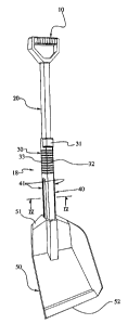
The shovel according to the invention as shown in the
accompanying drawings comprises three main parts, namely a
hand grip l0, a handle 18 and a blade 50.
The blade 50 has a front edge 52 and a rear portion 51
designed to receive the handle 18 and be connected to the
same. The blade 50 is made of a single piece of plastic
material. Alternatively, it can be made of metal.
The handle 18 has a front surface 32 and a back surface 33.
The handle 18 is preferably telescopic and comprises an
extendable portion 20 which is telescopically mounted
CA 02132046 2003-08-27
7
within a main portion 30. Specifically, the extendable
portion 20 can be reversibly moved between a position where
the extendable portion 20 is retracted inside the main
portion 30 and a position where the extendable portion 20
is fully extended. The extendable portion 20 can be
fastened in the fully extended position by means of snap
lock consisting of a piece of resilient plastic material 69
inserted into the base of the extendable portion 20. This
piece of resilient plastic material 69 has a pin 68 which
Projects towards the front surface 32 of the handle 18 in
order to snap into a hole 39 drilled into the main portion
30. The tongue 68 can be released by a collar 31, similar
to the one disclosed in Canadian Patent 1,277,462 and
United States Patent 4,908,900, so that the extendable
portion 20 can be slidably retracted inside the main
portion of the handle.
In accordance with an essential aspect of the invention,
the handle 18 has a portion 40 adjacent to the blade 50
which is made flexible so as to permit flexion of the
handle 18 to a given extent, exclusively in a plane
perpendicular to the front edge 52 of the blade 50.
In a first embodiment of the invention shown in Figures 1
to 16, this flexible portion 40 is preferably made of
hollow plastic material having fins 41 extending
longitudinally along it so as to permit flexion exclusively
in a plane perpendicular to the front edge 52 of the blade
50.
In this particular embodiment, the shovel can be made even
more compact. Thus, the rear portion 51 of the blade 50
CA 02132046 2003-08-27
7a
may have an opening 54 having guard rails 53 such that the
flexible portion 40 can be inserted in the opening 54 and
the fins 41 fit inside the guard rails 53. This permits
2132046
8
reversible movement of the flexible portion 4o between a
position where the flexible portion 40 is partially
retracted inside the blade 50 and a position where the
flexible portion 40 is fully extended. The flexible
portion 40 can be fastened in the fully extended position
by means of another snap lock mechanism which comprises a
rectangular opening 65 at the base of the rear portion 5'
of the blade, and a tongue 61 having a protuberance 64.
The protuberance 64 locks into the rectangular opening 65
when the flexible portion 40 is extended. The mechanism
can be released by a push button 62, which clears the
protuberance 64 from the rectangular opening 65 so that the
flexible portion 40 can be retracted. The flexible portion
40 is prevented from slipping off the blade 5o by a pair of
hooks 63 at the base of the flexible portion 40.
The advantage of having the shovel telescopic is that it
makes its storage easy and compact, particularly if the
shovel is to be stored in a vehicle such as a car. In this
connection, compare Figures 2 and 3.
In a second embodiment of the invention shown in Figures 17
to 23, the flexible portion 40 comprises a piece of
resilient plastic material 42 having transverse recesses 46
of given width at equal distances along the length of the
piece of resilient plastic material 42, opening on the back
surface 33 of the handle 18. Sections of elastomer 43 are
fastened within all the recesses 46. Preferably, these
sections of elastomer are made in a single piece 49 which
is fastened to the piece of resilient plastic material 42.
The flexible portion 40 is fastened to the blade 5o at one
end and fastened to said handle 18 at the other end. The
piece of resilient plastic material lies in the same plane
as the front edge 52 of the blade 50 and at the front
surface of the shovel so as to permit the elastomer 43 to
2132~~~
9
compress and the lateral walls 47 to distort slightly, as
can be seen in Figure 23, when in use.
The flexible portion 40 of the second embodiment described
above may also include a sleeve 44 for use to adjust the
amount of resiliency of the portion 40. As can be seen in
Figures 18, 19, 20 and 21, the sleeve 44 is fastened along
the piece of flexible plastic material 42 by snapping a
push button 45 inside holes 48 drilled at predetermined
distances in the piece of flexible plastic material 42 on
the front surface 32 of the handle.
When all recesses are covered by the sleeve 44, the
flexible portion 40 exhibits no resiliency and when all the
recesses are uncovered by the sleeve 44, the shovel
exhibits maximum resiliency. Thus the user can adjust the
resiliency of the flexible portion 4o so that it absorbs as
little or as much as he or she desires.
Although the present invention has been described
hereinabove by means of a preferred embodiment thereof, it
should be pointed out that any modification to these
preferred embodiments, within the scope of the appended
claims, is not deemed to change or alter the nature of the
invention.
Thus, for example, the flexibility of the shovel could be
obtained, as shown in Figures 24 and 25, by replacing the
flexible portion of the handle with a rotating mechanism
consisting of a spring 73 mounted around a pin 72 extending
inside the handle 18. The pin 72 is inserted through the
rear portion 51 of the blade 50 and is prevented from
slipping inside the handle 18 by a head or nut 75. At the
other end, a nut 76 and washer 77 prevent the spring 63
from slipping off the pin 72. The spring 73 is designed so
. .. _2132046
that it extends inside the handle exclusively and its
natural resiliency holds the pin firmly in place. Inserted
between the handle 18 and the rear portion 51 of the blade
50 is a piece of elastomer 74. A cover 71, preferably made
5 of plastic, is snapped on the front surface 32 of the
handle to hide the mechanism.
When the user uses the shovel in a digging motion, the
blade is forced to rotate clockwise in a limited manner
l0 about a first axis "X" which is downwardly spaced from the
pin 72. This in turn forces the spring 73 to compress and
thus absorb part of the impact, as shown in Figure 24.
Afterwards, when the user uses the shovel in a shovelling
motion, lifting the load forces the blade 50 to rotate
counter-clockwisely in a limited manner about a second axis
"Y" which is upwardly spaced apart from the pin 72, thereby
compressing the piece of elastomer, as shown in Figure 25.
Instead of using such a mechanism, the flexibility of the
shovel could be obtained by pivotably fastening the handle
to the blade by means of a pin transversely inserted
through the rear portion of the blade and the handle, where
the rear portion is shaped like an open wedge. The pin
would be fastened at both ends to the rear portion of the
blade. A coil spring would then be mounted around the pin
between the rear portion of the blade and the handle, and
fastened at one end to the rear portion of the blade and at
the other end to the handle. The spring has a given
resiliency so that when the user digs or shovels, the
spring would absorb part of the initial shock or load and
then return the blade to its static position.