Note: Descriptions are shown in the official language in which they were submitted.
CLAMP RING ASSE2~I13L5C FOR AIR SPRING
UACRGROUND -O_F' TFxE INVENTION
Technical Field
The invention relai~es to clamping means and more
particularly to the clamping means adapted to affix a
resilient elastomeric sleeve member to a relatively rigid
piston member or end cap of an air spring. Specifically, the
invention relates to a clamp ring assembly employing a
clamping ring having at least a pair of recesses on the inner
diameter thereof which coact with a corresponding member of
projections on the outer diameter of the piston member or end
cap to positionally locate the clamping ring on the piston
member and to effectively seal the open end of the elastomeric
sleeve therebetween.
Background Information
Pneumatic springs commonly referred to as air
springs, have been used for many applications, including motor
vehicles, for a number of years to provide cushioning between
moveable parts of the vehicle, primarily to absorb Shock loads
impressed on the vehicle axles by the wheels striking an
object in the road or falling into a depression. The air
spring usually consists of a flexible rubber sleeve or bellows
containing a supply of compressible fluid and has one or more
pistons movable with respect to the flexible sleeve. The
piston causes compression and expansion of the fluid within
the sleeve as the sleeve compresses and expands as the vehicle
experiences 'the road shock. The spring sleeve is formed of
a flexible elastomeric material containing reinforcing cords,
and permits the piston to move axially with respect to another
piston or end cap secured within open ends of the sleeve.
1
The open ends of the sleeves are sealingly connected
to the piston and/or opposite end cap, and the integrity of
this connection is always one of the important and major
aspects in producing an efficient and maintenance free air
spring. Another problem with existing air springs, and in
particular, the clamp ring therefore, is that the clamp ring
will move in its clamped position under dynamic air spring
conditions causing movement of the clamped elastomeric
material therebetween tending to loosen the sealing engagement
and deteriorating the clamp integrity and causing ultimate air
spring leakage and failure. This ring movement is especially
critical during the jounce or collapsing stroke.
Another problem with existing air springs and the
clamping of the elastomeric sleeve ends to the piston member
and/or end cap is to secure a sufficiently tight seal to be
able to withstand high fluid pressures contained in the fluid
chamber without premature leakage or bursting even upon
experiencing severe air spring movement and being exposed to
the harsh environments on the undercarriage of a vehicle.
Some examples of air springs and band sealing
devices are shown in the following patents described below:
U.S. Patent No. 3,788,628 discloses a pneumatic
spring-type system which includes a structure for anchoring
the inner ends of a flexible rolling sleeve. The sleeve is
positioned between surfaces characterized by having a saw
toothed shape with a circumferential groove and rib on an
inner circumferential surface and two ribs on an outer
circumferential surface. The opposite sides of the grooves
converge at predefined angles with predetermined and matching
radius of curvatures, the combination of which provides a
gripping action to hold the flexible sleeve firmly in place
by means of the saw-tooth design, in cooperation with the
matching recess of the ring and sleeve flange.
U.S. Patent No. 3,870,286 shows a fluid spring
wherein the ends of the rolling sleeve are secured by annular
2
clamping rings which engage against the internal surface of
the sleeve. The clamping ring secures the rolling sleeve to
the working cylinder. The c:Lamping ring contains an annular
groove deformation by which the rolling sleeve is held in
place by virtue of this interacting groove-shaped design in
combination with the clamping force exerted by the ring.
U.S. Patent No. 4,489,474 relates to means for
connecting a tubular flexible member to a piston which
includes a recess near the piston end to which is secured a
flexible member. The flexible member is wrapped over and
around a ring-shaped fitting which secures the flexible member
to the piston. The piston comprises a circumferentially
extending recess adjacent to its end with the flexible sleeve
being positioned and substantially filling the recess of the
piston. The ring-shaped fitting is a conventional swaged ring
and the end portion of the flexible member is trimmed from the
portion extending from the piston ring with the flexible
member substantially filling the recess of the shoulder of the
piston. The piston employs a serrated edge to assist in
griping of the flexible member.
U.S. Patent No. 4,573,692 discloses an assembly for
sealing two members, one of which has a cylindrical surface
which supports the seal, wherein a sealing lip is provided to
bear against the second member. A cylindrical surface
supports the seal which comprises a hollow-cylindrical body
having a lip which extends outwardly from the body with an
elastomeric band circling the body to hold it firmly in place.
The cylindrical surface contains a recess which extends
circumferentially around the surface and receives a matching
projecting element of the seal which extends from the inside
diameter of the cylindrical body.
U.S. Patent No. 4,629,170 shows a pneumatic spring
with a pair of chambers formed by a pair of membranes that are
sealingly attached to an axially spaced apart retainer and
piston wherein the axial end of the membrane is compressed
3
CA 02132371 2004-02-20
between a serrated surface of a solid member and a
retaining ring. The ring is swaged, fitted or otherwise
tightened to produce radial compression against the axial
ends of the flexible membrane.
5 British Patent No. 199,789 discloses a metal securing
band which grips a diaphragm and forces it against a
tapered end portion of a tubular member.
U.S. Patent No. 4,718,650 shows an air spring in which
the ends of the flexible sleeves are connected to the
10 sealing surfaces of a pair of axially spaced pistons by
swaged or crimped clamping rings. The piston clamping
surfaces are formed with serrations to assist the retention
of the elastomeric material when forced therein by the
clamping rings.
15 Other types of piston and end cap sealing arrangements
for air springs are shown in U.S. Patents Nos. 4,784,376;
4,787,607 and 4,787,606, all of which have been assigned to
the Assignee of the present invention.
Another known prior art air spring construction
20 includes a radially extending shoulder formed on the piston
member on which the clamping ring seats and sealingly
clamps the cut end of the flexible sleeve against a
plurality of uniformly raised ribs formed on the axially
extending sealing surface of the piston member adjacent the
25 annular shoulder. However, such construction presents
problems in that the clamp ring is not positively
positioned on the annular shoulder, and is free to move in
an upward axial direction upon the air spring experiencing
severe jounce or extended positioning.
30 Many of the problems discussed above are solved by the
clamping arrangement shown in U.S. Patent Nos. 4,899,995
and 4, 852, 861 . These patents show the use of a clamp ring
having a single centrally located recess which aligns with
an outwardly extending projection formed on the sealing
35 surface of the piston and end member in order to position
the clamping ring on the piston or end member. A pair of
pinch areas are
4
formed on opposite sides o;E the projection by outwardly
extending annular rings or surfaces on the sealing surfaces
of the piston and/or end member. These rings form the pinch
areas or zones in cooperation with the axially extending inner
annular surface of the clamp ring on opposite sides of the
concave recess. Although this clamp ring assembly does solve
many of the problems discussed above and is extremely
efficient for many applications, it has been found that for
certain air spring applications, especially for larger air
springs having high internal pressure, it may not provide the
necessary clamping power.
Therefore, the need exists for a still further
improved clamp ring assembly for air springs which provides
increased clamping and sealing for the open ends of the
elastomeric member between the clamp ring and end member
and/or piston.
SUMMARY OF THE INVENTION
Objectives of the invention include providing an
improved clamp ring assembly for air springs, primarily used
for motor vehicles, having a piston at one end and an end cap
at an axially spaced opposite end, with a flexible elastomeric
sleeve extending therebetween and clamped against the
respective end cap and piston member by clamp rings to form
a fluid tight seal therebetween and provide an intervening
pressure chamber.
A still further objective of the invention is to
provide such a clamp ring assembly in which movement of the
clamp ring is reduced when operating under dynamic conditions
by positioning the ring directly adjacent a shoulder of the
piston member or an annular flange of the end cap thereby
maintaining a positive sealing effect with the elastomeric
sleeve clamped between the ring and adjacent end member.
A still further objective of the invention is to
5
provide such an improved clamp ring assembly in which the
piston member or end cap clamping surface includes at least
a pair of annular projection~> which act in cooperation with
a~ corresponding number of concave grooves on the clamp ring
to facilitate efficient gripping of the elastomeric material
therebetween and to alter the direction of the reinforcing
cords contained within the elastomeric sleeve, to further
increase the clamping effect of the ring, and which
positionally locates the clamp ring on the sealing surface of
the piston meiriber or end cap.
A further objective is to provide such an improved
clamp ring assembly in which annular expansion grooves are
formed between the projections on the piston member and end
cap member sealing surfaces to permit the elastomeric material
to flow therein to form bead-like holding members.
Another objective is to provide such an improved
clamp ring assembly in which the outer surface of the clamp
ring generally aligns with the adjacent outer surface of the
piston or end cap to provide a generally continuous surface
between the clamp ring and piston member or end cap over which
the elastomeric sleeve rolls, to provide a smooth interface
therebetween to reduce wear on the elastomeric sleeve as it
moves along the surfaces of the piston member or end cap and
clamping ring during dynamic operation of the air spring.
A further objective is to provide such an improved
clamp ring assembly in which the radial distance between the
outer surfaces of the annular projections of the piston and/or
end member sealing surfaces is spaced from the bottom curved
surfaces of the concave recesses in the clamp ring a distance
generally equal to 500 of the thickness of the elastomeric
sleeve to be sealingly clamped therebetween.
Still another objective of the invention is to
provide such a clamp ring assembly in which the concave
recesses of the clamp ring are separated by generally flat
surfaces having the same diameter as the remaining portions
6
w ~:~~z~~z
of the clamp ring inner surface thereby enabling the clamp
ring to be formed from a ring blank having a uniform inner
thickness or diameter to achieve the most efficient use of the
clamp ring material and to reduce costs of constructing the
clamp ring.
These objectives and advantages are obtained by the
improved clamp ring assemble of the invention, the general
nature of which may be stated as including a pair of end
members adapted to be mounted at generally axially spaced
locations; a flexible sleeve formed of an elastomeric material
containing reinforcing cords and having open ends sealingly
engaged with the end members forming a fluid chamber
therebetween; an annular axially extending sealing surface
formed on at least one of said end members, said sealing
surface being formed with a pair of axially spaced annular
projections extending radially outwardly; an annular clamp
ring located concentrically with respect to the annular
sealing surface of said one end member for sealingly clamping
one end of the flexible sleeve therebetween, said clamp ring
having an axially extending inner clamping surface formed with
a pair of recesses, each cooperating with a respective one of
the annular projections to positionally locate said ring with
respect to said one end member, and for providing a pair of
axially spaced pinch areas for clamping the flexible sleeve
therebetween and for changing the direction of travel of the
reinforcing cords in the clamped sleeve end; at least three
grooves being formed in the sealing surface of said one end
member providing expansion zones for receiving elastomeric
material of the sleeve therein, one of said grooves being
intermediate the pair of projections with the other two
grooves being located on other sides of said projections; and
a radially outwardly extending annular shoulder formed at one
end of the annular sealing surface of said one end member for
abutting the clamp ring to restrict movement of said clamp
ring in the axial direction during operation of 'the air
7
spring.
BRxE~ DESCRxPTxaN of THE DR~wxNGs
A preferred embodiment of the invention illustrative
of the best mode in which applicant has contemplated applying
the principles, is set forth in the following description and
is shown in the drawings and is particularly and distinctly
pointed out and set forth in the appended claims.
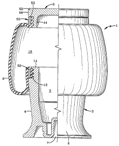
FIG. 1 is an elevational view of the improved
clamping ring assembly incorporated into an air spring, with
portions broken away and in section, with the air spring being
shown in a static at-rest position;
FIG. 2 is a greatly enlarged fragmentary sectional
view showing the clamp ring assembly securing one end of the
elastomeric sleeve against the sealing surface of an end cap;
FIG. 3 is a great~.y enlarged fragmentary sectional
view similar to FIG. 2 showing the clamp ring assembly
securing another end of the elastomeric sleeve against 'the
sealing surface of the piston member:
FIG. 4 is a top plan view of the clamp ring of the
improved clamp ring assembly of the invention; and
FIG. 5 is a sectional view of the clamp ring taken
on line 5-5, FIG. 4.
Similar numerals refer to similar parts throughout
the drawings.
DESCRIPTION OF THE PREFERRED EMBODIMENT
Two of the improved clamp ring assemblies of the
invention are shown in FIG. 1 mounted on an air spring, which
is indicated generally at 1, and which is shown in an at-rest
position. Air spring 1 includes axially spaced end members
consisting of an end cap and a piston member, indicated
generally at 2 and 3 respectively. Piston member 3 may have
8
CA 02132371 2004-02-20
various configurations, with that shown in the drawings
being an example of one type. Member 3 is cup-shaped
having a generally conical shaped outer wall 4 forming an
open interior 5 in a base 6 which is formed with a recessed
5 central bottom portion 7. A flexible sleeve 8 formed of
elastomeric material and containing internal reinforcing
cords 9 (FIGS. 2 and 3), extends between end cap 2 and
piston member 3 which are clampingly engaged within the
open ends of the sleeve by the clamp ring assembly of the
10 invention, in order to form a fluid pressure chamber 18
therebetween.
In accordance with the invention, an improved axially
extending clamping surface indicated generally at 10, is
formed on a reduced diameter upper end portion 11 of piston
15 member 3, shown in detail in FIG. 3. Clamping surface 10
is connected to conical outer wall 4 of the piston member
by a radially extending shoulder 12 and a curved corner 13.
The open outer end of piston end portion 11 has a radially
extending flat surface 14 which terminates in an annular
20 stepped surface having first and second annular portions
indicated at 15 and 16, respectively, with portion 15,
having a larger diameter than portion 16.
In accordance with the invention, clamping surface 10
includes a pair of annular radially extending clamping
25 projections 19 and 20. Annular projections 19 and 20 are
of equal diameters and preferably terminate in convex outer
ends 21 and 22, respectively. Projections 19 and 20 are
separated by an annular material expansion groove 23 which
has an inwardly tapered configuration formed by flat sides
30 which terminate in a generally flat bottom surface,
providing a generally truncated configuration.
A pair of material expansion grooves 26 and 27 are
formed on the other sides of projections 19 and 20, with
groove 26 being formed by one tapered side of projection 19
35 and a generally flat radially extending surface 28 which
merges with stepped portion 16. Groove 27 is formed by a
tapered side of
9
~~~z~~r~
proj ection 20 and the innermost portion of radial shoulder 12 ,
Grooves 23, 26 and 27 provide expansion areas or
zones for the movement of the elastomeric material of flexible
sleeve 8 therein, and provide for the formation of three bead
s like members 29 which assist greatly to prevent axial pull out
of the sleeve end when clamped thereon as described below.
In further accordance with the invention, the clamp
ring assembly includes a clamp ring indicated generally at 32,
(FIGS. 4 and 5), preferably formed of aluminum or of a high
strength plastic. Ring 32 has a pair of recesses 33 and 34
which are formed in an inner axially extending surface 35
thereof, which extends between circumferential end surfaces
36 and 37. Inner surface 35 preferably is parallel with an
axially extending outer diameter ring surface 38, with inner
and outer diameter surfaces 35 and 38 being connected to
eircumferential end surfaces 36 and 37 by four rounded corners
39. Recesses 33 and 34 preferably are concave and have
rounded bottom surfaces and are of equal depths, and are
separated by a flat annular surface 40. Surface 40 preferably
has the same diameter as inner surface 35 which enables ring
32 to be formed out of an annular band having an inner
diameter the same as surfaces 35 and 40, which eliminates
machining operations thereon, which would be required if
surface 40 was of a different diameter than surface 35.
Referring again to FIG. 3, recesses 33 and 34 of
clamp ring 32 radially align and cooperate with convex
projections 19 and 20 of piston clamping surface 10 to
positionally align the clamp ring on the piston sealing
surface for receiving the open end of flexible sleeve 8
therebetween. In this position, circumferential end surface
37 of the clamp ring seats upon or is located closely adjacent
to annular shoulder 12, which prevents movement of clamp ring
32 in the downward axial direction in reference to FIGS. 1 and
3, during the operation of the air spring. This is especially
critical during the jounce of collapse position of the air
spring in which piston 3 moves axially towards end cap 2.
In accordance with one of the main features of the
invention, convex outer ends 21 and 22 of projections 19 and
2~0 are spaced from 'the curved bottom surfaces of clamp ring
recesses 33 and 34 a distance within the range of 40% to 60%
of the thickness of sleeve 8, which is represented by arrow
A in FIG. 3, to provide a pair of spaced pinch areas 42 and
43 on the elastomeric sleeve material. Preferably the
distance between outer ends 21 and 22 and the bottom curved
surfaces of recesses 33 arid 34 is 50% of the thickness of
sleeve 8. The top annular portion of inner clamp ring surface
35 is spaced from a rounded corner 30 which connects radial
surface 28 with annular portion 16, and is separated therefrom
by a~distance indicated by arrow B, which again is generally
equal to distances A described above, that is between 40% and
60% of the material thickness of sleeve 8 to provide another
pinch area.
Furthermore, as shown in FIG. 3, expansion grooves
23, 26 and 27 receive the elastomeric material of sleeve 8 as
it is squeezed between the bottom surfaces of recesses 33 and
34 and ends 21 and 22 of projections 19 and 20, which further
assists in providing a tight clamping engagement between clamp
ring 32 and piston clamping surface 10. The volume provided
i by the three expansion grooves preferably is greater than the
volume of the rubber which is squeezed thereinto, which will
permit annular void areas at the bottoms of grooves 23, 26 and
27 to ensure that the desired clamping force is achieved
between the projections and ring recesses.
In accordance with another feature of the invention
as shown in FIG. 3, reinforcing cords 9 are caused to change
directions several times due to the radial outward extensions
of projections 19 and 20 into the aligned clamping ring
recesses 33 and 34. This provides a tighter and more stable
clamping engagement with the trapped sleeve end since a
greater force will be required to pull the sleeve end from
11
CA 02132371 2004-02-20
between the clamp ring and clamping surface of the piston
then would be required if the trapped elastomeric material
and reinforcing cords were in a generally straight
alignment.
5 Referring to FIGS . 1 and 2, end cap 2 is formed with
an annular axially extending body 44 having an outer
axially extending annular sealing surface indicated
generally at 45. Sealing surface 45 is formed with a pair
of projections 46 and 47 similar to piston projections 19
10 and 20, and three material expansion grooves 48, 49 and 50,
similar to expansion grooves 23, 26 and 27 of piston 3.
End cap 2 preferably is provided with a radially extending
annular top flange 52 having an annular radial shoulder 53
which communicates with end expansion groove 50. The end
15 of end cap 2 opposite top flange 52 has a stepped annular
area with a pair of annular portions 51 and 54, with
annular portion 54 forming a pivot zone indicated by arrow
C, similar to the pivot zone B of piston 3 as shown in FIG.
3. Furthermore, an end cap clamp ring 55 which is similar
20 to clamp ring 32 of the piston member, is provided for
clamping the elastomeric sleeve against sealing surface 45,
and thus is not described in greater detail.
The relationship of the various grooves and
projections of end cap sealing surface 45 in cooperation
25 with clamp ring 55 is similar to that described above with
respect to piston clamping surface 10 and clamp ring 32.
Also, outer annular surface 56 of end cap flange 52 axially
aligns with outer annular surface 57 of clamp ring 55 to
provide a generally continuous surface over which flexible
30 sleeve 8 will move when the air spring is in the jounce
position to avoid any sharp bends and to provide continuous
transition between the aligned surfaces in a similar manner
as provided by outer surface 38 of clamp ring 32 and outer
wall 4 of the piston member as shown in FIG. 3.
35 It has been found that annular projections 19 and 20,
and projections 46 and 47, in cooperation with the bottom
surfaces of the corresponding concave recesses formed in
clamp
12
rings 32 and 55, provides increased holding power for
maintaining the trapped sleeve ends, than that provided by the
pair of spaced pinch zones provided by the single projection
and recess and pair of adjacs:nt projections of the clamp ring
assembly of Patent No. 4,899,995. This increased holding
power is believed to occur due to the additional direction
changes of the sleeve material and in particular by changes
of direction of the reinforcing cords 9 embedded therein.
Also, this groove configuration in the piston and end cap
sealing surfaces provides for the formation of three bead-like
members 29 which further assist in trapping the sleeve ends
in their respective end members and further resist pull-out,
even when a relatively high internal pressure is placed within
fluid chamber 18.
Accordingly, the improved clamp ring assembly for
an air spring is simplified, provides an effective, safe,
inexpensive, and efficient assembly which achieves all the
enumerated objectives, provides for eliminating difficulties
encountered with prior clamping assemblies, and solves
problems and obtains new results in the art.
In the foregoing description, certain terms have
been used for brevity, clearness and understanding; but no
unnecessary limitations are to be implied therefrom beyond the
requirement of the prior art, because such terms are used for
descriptive purposes and are intended to be broadly construed.
Moreover, the description and illustration of the
invention is by way of example, and the scope of the invention
is not limited to the exact details shown or described.
Having now described the features, discoveries and
principles of the invention, the manner in which the improved
clamp ring assembly for an air spring is constructed and used,
the characteristics of the construction, and the advantageous,
new and useful results obtained; the new and useful
structures, devices, elements, arrangements, parts and
combinations, are set forth in the appended claims.
13