Note: Descriptions are shown in the official language in which they were submitted.
~--` 2132380
Case 1109
MEASURING DEVICE FOR REMOVABLE SENSORS
The present invention concerns a measuring device
intended to be used with a removable sensor. For example,
such a measuring device is used to carry out measurement
of the electrochemical type, in particular to measure the
glucose level in blood. The electrochemical functioning of
such a measurement is described for example in patent
application WO 92/14 836.
More particularly, the present invention concerns the
electrical connection between such a measuring device and
a removable sensor used with this measuring device.
Figure 1 shows a schematical general view of a
measuring device, designated by the general reference 2,
and a removable sensor designated by the reference 4.
Removable sensor 4 comprises an active zone 6 and two
contact surfaces 8 and 10 electrically connected to active
zone 6 via two conductors which are not shown.
Figure 2 shows a schematical view of a conventional
electrical connection between a measuring device
(partially shown) and a removable sensor of the type shown
in figure 1.
The electrical connection is realised by two metallic
strips connected respectively to the two contact surfaces
8 and 10, the latter being electrically connected in
series to active zone 6 of removable sensor 4.
In order to enable removable sensor 4 to be
introduced into the measuring device or to be withdrawn
from the latter, the electrical connection is ensured only
by pressure from metallic strips 12 and 14 on ithe
respective contact surfaces 8 and 10, these strips 12 and
14 ~
exhibiting a certain elasticity. ~ -
The electrical connection arrangement described above
is not very reliable. Indeed, it can easily happen that
one of the metallic strips becomes distorted following the
~. . , ~.~ ,..
''. . ~
~132380
repeated introduction of removable sensors or that the
pressure exercised by the metallic strip is insufficient
to establish a proper electrical connection. Further,
removable sensor 4 may be defective and the contact
surfaces may have, for example, an abnormal electrical
resistance.
The different problems cited above are especially
disastrous for measurements of a medical nature.
A purpose of the present invention is to overcome the
lack of security of the electrical connection between a
measuring device and a removable sensor intended to be
used with this measuring device.
The present invention therefore concerns a measuring
device intended to be used with a removable sensor having
at least two electrical contact surfaces, this measuring
device comprising measuring means and connection means
comprising at least two first contact means. These two
first contact means are used respectively to establish an
electrical connection between the two contact surfaces of
said removable sensor and the measuring means. This
measuring device is characterised in that said connection
means also comprises two second contact means, the two
second contact means being used respectively to connect
electrically the two contact surfaces of said removable
sensor to testing means enabling said electrical
connection between each of the two first contact surfaces
and said measuring means to be tested.
The doubling of contact means according to the
invention between the measuring device and the removable
sensor with which it is used enables, according to
different embodiments, at least one electric circuit to be
established, not including the active zone of the
removable sensor and enables one to test whether the
electrical connection bet~een the first contact means and
the respective contact surfaces of said removable sensor
is correctly established, to the extend that the
electrical connection between the second contact means and
3 2l3238o
the respective electrical contact surfaces of said
removable sensor is also correctly established.
It is therefore possible, before carrying out a
measurement by the intermediary of the measuring device
and the removable sensor with which it is used, to ensure
that the establishment of an electrical connection between
each of the first or second contact means intervening in
the measurement and the removable sensor is correctly
established.
According to another characteristic of the invention,
it is also possible to test whether the sensor used for
measuring is defective.
Other advantages and characteristics of the invention
will become clear with the help of the following
description made with reference to the attached drawings,
given purely by way of a non-limitative example, in
which :
- figure 1, already described, shows in perspective
a general view of a measuring device and a removable
sensor with which it is used;
- figure 2, already described, is a partial view of
a measuring device of the prior art schematically showing
the electrical connection between the measuring device and
a removable sensor with which it is used;
- figure 3 shows in perspective a schematical view
of a measuring device according to the invention used with
a removable sensor;
- figure 4 shows a schematical view of a first
embodiment of the electric circuit of the measuring device
according to the invention.
- figure 5 shows a schematical view of a second
embodiment of the electric circuit of the measuring device
according to the invention.
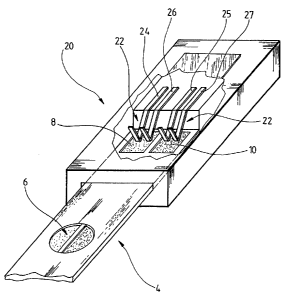
In figure 3, the measuring device according to the
invention, designated by the general reference 20, is used
with a removable sensor 4 comprising at least an active
zone 6 and two electrical contact surfaces 8 and 10. These
42l32380
electrical contact surfaces 8 and 10 are electrically
insulated from each other and are electrically connected
to active zone 6 by means of two respective conductors
(not shown) integrated into removable sensor 4.
Measuring device 20 includes connection means 22
formed by four electrical contacts 24, 25, 26 and 27,
consisting respectively of four metallic strips or wires.
These four metallic strips 24 to 27, used as electrical
contact means between measuring device 20 and removable
sensor 4, are bent and exhibit a certain elasticity
enabling them to rest on electrical contact surfaces 8 and
10 of removable sensor 4, that is to say, to exercise a
certain contact pressure on said electrical contact
surfaces 8 and 10.
Thus, each of two electrical contact surfaces 8 and
10 is used with two electrical contacts 24 and 26, 25 and
27, independent of each other. This doubling of electrical
contacts by electrical contact surface enables the
electrical connection between removable sensor 4 and
measuring device 20 to be tested by means of an electric
or electronic circuit arranged in said measuring device.
Two embodiments of this electric circuit of measuring
device 20 according to the invention will be described
below.
In figure 4 a first embodiment of the electric
circuit of a measuring device according to the invention
is shown.
Figure 4 shows a schematical diagram of two
electrical contact surfaces 8 and 10 of a removable sensor
and the four electrical contacts 24, 25, 26 and 27 of a
measuring device according to the invention which are used
with them.
It should be noted here that the removable sensor is
a multiple zone sensor comprising a plurality of active
zones 6a, 6b, 6c, electrically connected in parallel to
two electrical contact surfaces 8 and 10, there being any
number of these actives zones. The electric circuit of the
2S132380
measuring device according to the invention comprises
measuring means 30 and testing means comprising a testing
electronic unit 32 and testing resistor 34. It will be
noted that measuring means 30 and testing electronic unit
32 may be formed by one and the same electronic unit.
Electrical contacts 24 and 27 used respectively with
contact surfaces 8 and 10 are connected to measuring means
30. On the other hand, electrical contacts 25 and 26 used
respectively with electrical contact surfaces 8 and 10 are
connected to testing resistor 34. In this embodiment, the
value of the electrical resistance of active zones 6a, 6b
and 6c, when these active zones are not in contact with a
substance which is electrically conductive in conjunction
with one of said active zones, is very high, more
particularly almost infinite.
In order to be able to test whether the electrical
connections between electrical contact 24 and contact
surface 8 and between electrical contact 27 and contact
surface 10 are correctly established, electrical contacts
24 and 27 are capable of being electrically connected to a
voltage source (not shown) which is part of measuring
means 30 and/or testing electronic unit 32. It is
envisaged that testing resistor 34 has a value enabling an
electric test current IC to be established when electrical
contacts 24 and 27 are connected to said voltage supply.
Testing resistor 34 has, for example, a value of the order
of several tens of KQ~ in particular 30 KQ.
It is advantageous for the voltage source used to
establish an electric test current IC to be a constant
voltage supply. Thus, knowing the value of testing
resistor 34, it is possible to determine the minimal value
of an electric test current IC required to flow through
testing resistor 34 when the electrical connection between
four electrical contacts 24, 25, 26 and 27 and two
electrical contact surfaces 8 and 10 is correctly
established.
21,~2380
In order to test whether said minimal value is
achieve during a testing phase, namely a phase in which
active zones 6a, 6b and 6c are not in contact with any
substance which is electrically conductive in conjunction
with one of the active zones, testing means 32 comprises
means for comparing (not shown) the value of electric test
current IC to a first reference value approximately equal
to said minimal value.
In an alternative of this first embodiment, test
current IC may be stored, the value of this test current
IC being taken into consideration by measuring means 30 at
the time of measuring a substance to be analysed by means
of at least one of active zones 6a, 6b and 6c of the
removable sensor used with the measuring device according
to this first embodiment of the invention.
It will also be noted that the resistance of testing
resistor 34, electrically connected in parallel with
active zones 6a, 6b and 6c to measuring means 30, is to be
taken into consideration in the arrangement of measuring
means 30. For the sensitivity of the measuring device
arranged according to this first embodiment to be high, it
is preferable that the electrical resistance of each of
active zones 6a, 6b and 6c, when placed in contact with a
substance to be analysed, has a value less than the value
of testing resistor 34, for example, ten times smaller.
In another alternative of this first embodiment, said
means for comparing also enables the value of test current
IC to be compared to a second reference value. The
removable sensor used with the measuring device according
to this alternative, is considered to be defective when
the value of test current IC is greater than this second
reference value. This comparison notably enables a defect
in one of active zones 6a, 6b or 6c or a short-circuit
intervening in t.he removable sensor to be detected.
Thus, during a testing phase prior to a measurement,
the measuring device used with a removable sensor is
judged to be in a correct operating condition when the
~ . .
. ~:
721 32380
~ ~ ,.
value of test current IC is included between the first
reference value and the second reference value. To this
end, the testing means of the measuring device according
to the invention is arranged to indicate that this
measuring device used with a removable sensor introduced
into the latter is not functioning when the value of the
test current is less than said first reference value or
greater than said second reference value.
Referring to figure 5, a second embodiment of the
electric circuit of a measuring device according to the
invention will be described below.
In figure 5 two electrical contact surfaces 8 and 10
of a removable sensor and active zone 6 of this removable
sensor are also shown.
Each of two electrical contact surfaces 8 and 10 is
also used with two electrical contacts 24 and 26, 25 and
27 belonging to the measuring device. This measuring
device also comprises measuring means 40 and testing means
comprising a testing electronic unit 42 and two switches
44 and 46. Each of two switches 44 and 46 may be actuated
independently of each other by testing electronic unit 42.
The two switches 44 and 46 are electrically connected to
measuring means 40, each of these two switches 44 and 46
being capable of switching between a first terminal 48, 49
and a second terminal 50, 51.
The two terminals 48 and 50 of switch 44 are
connected respectively to electrical contacts 24 and 25,
which are respectively used with the two electrical
contact surfaces 8 and 10 of the removable sensor.
Similarly, the two terminals 49 and 51 of switch 46 are
respectively connected to the two electrical contacts 26
and 27, which are respectively used with the two
electrical contact surfaces 8 and 10. Measuring means 40
and/or testing electronic unit 42 comprise a voltage
source (not shown) capable of being connected in series to
the two switches 44 and 46.
28132380
This second embodiment of the invention enables the
electrical connection of electrical contacts 24 and 26
used with contact surface 8 and the electrical connection
of electrical contacts 25 and 27 used with electrical
contact surface 10 to be checked separately.
When switches 44 and 46 are connected respectively to
terminals 48 and 49, it is possible to test whether an
electric test current flows between electrical contacts 24
and 26 when the two switches 44 and 46 are connected in
series to said voltage source. Similarly, when the two
switches 44 and 46 are connected respectively to terminals
50 and 51, it is possible to test whether the electrical
connection between electrical contacts 25 and 27 and
electrical contact surface 10 is correctly established.
Thus, it is possible to test independently the state
of the electrical connections of each of the two
electrical contact surfaces 8 and 10. Further, this second
embodiment of the invention enables the electrical
connection between the removable sensor and the measuring
device to be tested without the resistance of active zone
6 to the passage of an electric current or the state of
active zone 6 having an effect on the test carried out.
Also, testing electronic unit 42 comprises means for
comparing enabling the value of an electric test current
flowing either between electrical contacts 24 and 26, or
between electrical contacts 25 and 27 to be compared to a
first reference value corresponding to a minimal current
below which the electrical connection is considered to be
incorrectly established.
This second embodiment also enables the state of
active zone 6 to be tested by switching switch 44 onto
terminal 48 and switch 46 onto terminal 51 or by switching
switch 44 onto terminal 50 and switch 46 onto terminal 49.
It is thus possible to test that the resistance of active
zone 6 of the removable sensor to the flow of an electric
current, when active zone 6 is not in contact with any
substance which is electrically conductive in conjunction
92I32380
,, ~, ;,
with this active zone, is not less than a determined
value.
To achieve the latter test, comparing means of ~ -
testing electronic unit 42 enables the value of an
electric test current capable of flowing through active
zone 6 to be compared to a second reference value. When
the latter electric control current has a value less than
this second reference value, the removable sensor is
considered to be defective. This defectiveness may arise
for example from the active zone itself or from a short-
circuit between the two conductors 54 and 56 electrically
connecting active zone 6 to contact surfaces 8 and 10.
Finally, it will be noted that the second embodiment
of the invention is also suitable for multiple zone
removable sensors, just as the first embodiment described
in figure 4 is suitable for single-zone removable sensors.
.