Note: Descriptions are shown in the official language in which they were submitted.
` s ~
~ ` ~ 3
15 41 CANADA
INSTRlJMEN'r FOR CLOSING TROCAR P~JNC'r~JRB ~O~JNDS
1. Field of the Invention
This invention relates to instruments for suturing
puncture wounds and more particularly to instruments for
closing trocar puncture wounds formed during endoscopic
surgical procedures.
2. Descri~tion of the Related Art
With laparoscopic and endoscopic surgery, a small -
incision or puncture i8 made in the patient's body to
provide access for a tube or a cannula device. Once
extended into the patient's body, the cannula allows for
insertion of various surgical instruments such as scissors,
dissectors, retractors, or biopsy instruments to perform
diagnostics and/or surgery. Upon completion of the
surgical procedure, the remaining trocar wound may require
some attention, e.g., in the form of placing sutures to
C105~ the wound. In certain cases it may be desirable to
close the wound from within.
A device which forms sutures from within the ;~
urethra is shown in Soviet Patent SU 1093329. The device is -
; inserted into the urethra and pivotally deploys needles from
, which eutures are subsequently pulled through the side walls
of the urethra.
Other devices have been developed which are used
to place sutures from within a wound. For example, co-
pending commonly assigned applications Serial No. 07/950,073
filed September 23, 1992 and Serial No. 08/013,244 filed
February 23, 1993 as well as co-pending application Serial
' . ~, ',
: -1- :~
~ ..' "'
~,
8 9
No. 07/876,511 relate to different surgical instruments for
placing sutures from within a trocar wound. U.S. Patent
Application Serial No. 08/091,793, filed July 14, 1993 also
discloses a surgical instrument for placing suture, the
contents of which are incorporated herein by reference.
Also, a device has been developed for placing sutures from
within a trocar wound which includes a needle clamping - -
device for capturing the needles upon deployment thereof.
Such a device is shown in a product brochure of REMA- -
Medizintechnik GmbH of Germany.
An improved instrument which provides better
deployment and capturing or shielding of the needles is
disclosed in commonly assigned co-pending application Serial
No. 08/134,144, filed October 8, 1993, the contents of which
are incorporated herein by reference
It would be advantageous to provide a reloadable
instrument which would allow replacement of fresh needles
and sutures to close several trocar wounds in the patient.
8UMNARY OF TH~ INV~NTION
The present invention provides a novel surgical
instrument for applying sutures through body tissue and
includes a lightweight and easy to use instrument which may - ~
be operated quickly and efficiently. ~¦
In one aspect of the present invention, the
instrument includes an elongated body having a proximal end
portion and a distal end portion, at least one needle
carrier member operatively mounted in the distal end portion
and movable between at least a retracted position and a
deployed position, a needle releasably retained in the at ~-
least one needle carrier member, a predetermined length of
suture material having one end affixed to the needle. The
instrument may include a suture material tensioning member
disposed within the elongated body for maintaining the
suture material in tension during movement of the at least -~
one needle carrier member from the retracted position to the
deployed position.
The instrument may also include a retaining
mechanism adapted to retain the at least one needle carrier
in the partially deployed position.
In another aspect of the present invention, the
instrument includes an actuator member operatively
associated with the at least one needle carrier member, the
actuator member being movable between at least a first
position and a second position to move the at least one
needle carrier from the lnitial position to the deployed
position, a needle retaining member disposed in the
elongated body and adapted to retain the needle therein when
the at least one needle carrier member is in the deployed
position, and a needle skewing mechanism operatively
associated with the actuator member such that upon movement
of the actuator member from the first position to the second
position the needle skewing mechanism contacts a tapered
portion of the needle to change the alignment thereof
relative to the retaining member.
A deployment indicator may be included in the
instrument to provide an indication to an operator of the
instrument when the at least one needle carrier member is in
the second position.
2S In alternate embodiments, the instrument is
reloadable to provide replacement with fresh needles and
sutures to close several trocar wounds in the patient. The
elongated housing portion, in one embodiment, is removably
mounted to a pistol grip handle housing to intermesh with a
gear mechanism for movement between a proximal and distal
position to deploy the needle structure. In an alternate
embodiment, the instrument comprises a pair of flexible
curved members mounted to a grip portion and a pair of
levers mounted to the curved members. The elongated member
has a groove to receive the levers to provide for distal
movement to deploy the needle structure. In another
-3-
.
embodiment, the elongated housing is removably mounted by a
bayonet mount to the handle portion. The inner rod is ~
deployed by depression of a push button mechanism. These -
instruments can incorporate the different aspects described
above.
..
BRIEF DESCRIPTION OF THE DRAWINGS
Preferred embodiments of the invention are
described herein below with reference to the drawings
wherein:
Fig. 1 is a perspective view of one embodiment of
the instrument o~ the present invention;
I Fig. 2 is a partial cross-sectional view taken
¦ along section line 2-2 of Fig. l;
! 15 Fig. 3 is an exploded partial-view with parts
f separated of the distal end of the instrument of Fig.1;
Fig. 4 is a cross-sectional view taken along
section line 4-4 of Fig. l; ~ -
Fig. 5 is a cross-sectional view taken along line
5-5 of Fig. 4;
Figs. 6-8 are views similar to Fig. 5, which show
the sequential operation of the needle deployment actuating ~ ~
mechanism of the instrument of Fig. 1; ~;
Fig. 9 is a cross-sectional view of the distal end ;~
o~ the instru~ent taken along 8ection line ~-9 of Fig. l and
8howing the needle carrier5 in the intermediate position in
phantom lines;
Fig. 10 is an enlarged view of the needle
deployment mechanism showing the needle carriers in the
fully deployed position:
Fig. 11 is an enlarged view similar to Fig. 10,
which shows the needle carriers retracting after the needles
have become embedded in the needle retaining members;
Fig. 12 is a partial plan view of the instrument
of the present invention with one half of the elongated body
removed to illustrate the suture material tensioning system;
-4-
..
'. '
Fig. 13 is a cross-sectional view taken along
section line 13-13 of Fig. 12;
Fig. 14 is a view similar to Fig. 12, which shows
the suture tensioning system after the deployment of the
needles;
Fig. 15 is a cross-sectional view taken along
section line 15-lS of Fig. 14;
Figs. 16-19 illustrate two alternative needle
retaining members for use with the instrument of the present
invention;
Fig. 20 is another embodiment of the needle
skewing mechanism ~or use with the instrument of the present
invention; and
Fig. 21 illustrates the deployment indicator for
lS the instrument of the present invention.
Fig. 22 is a perspective view of a first
embodiment of the apparatus of the present invention having
a reloadable needle and suture housing and utilizing a
pistol grip for deploying the needle carriers;
Fig. 23 is a side view of the apparatus of Fig.
22; ~`
Fig. 24 is a partial cross-sectional view of the
apparatus of Fig. 22 prior to deployment of the needle
carriers;
Fig. 25 is a partial cross-sectional view of the
apparatus o~ Fig. 22 showing the handle squeezed to deploy
the needle carriers; ;~
Fig. 26 is a perspective view of an alternate
embodiment of the apparatus of the present invention having
a reloadable needle and suture housing and utilizing a pair
of flexible handle members for deploying the needle
carriers;
Fig. 27 is a partial cross-sectional view of the
apparatus of Fig. 26 prior to deployment of the needle
carriers; ~
. ,. '' ,.:~.
-5- ` ;``
.j ~ J
.:
Fig. 28 is a partial cross-sectional view of the
apparatus of Fig. 26 showing the handles squeezed to deploy -
the needle carriers;
Fig. 29 is a perspective view of another alternate
embodiment of the apparatus of the present invention having
a reloadable needle and suture housing and utilizing a push
button mechanism for deploying the needle carriers;
Fig. 30 is a top view of the apparatus of Fig. 29;
Figs. 31 and 32 are rear and front views,
respectively, of the apparatus of Fig. 29;
Fig. 33 is an side view of the apparatus of Fig.
29, showing the elongated needle and suture housing
separated from the handle portion;
Fig. 34 is a perspective view of the elongated
needle and suture housing; ` ;~
Fig. 35 is a partial cross-sectional view of the
apparatus of Fig. 29 prior to deployment of the needle
carriers: and
Fig. 36 is a partial cross-sectional view showing
the button depressed and the needle carriers deployed.
D~TAIL~D DE8CRIPTION OF THB P~EFERRED EM~ODIMENT8 :
Re~erring now in specific detail to the drawings,
in which like reference numerals identi~y similar or
identical ele~ents throughout the several views, and
initially to Figs. 1-3, one embodiment of a suturing
instrument for closing puncture wounds in accordance with
the present invention is shown generally at 10. Suturing
instrument 10 is particularly adapted for driving a pair of
needles 12 and 14 from within the endoscopic cavity of a
¦ patient into the peripheral tissue adjacent an endoscopic
¦ puncture wound and placing a suture therein. However,
instruments which utilize more or less than two needles are
also within the scope of the present invention.
Generally, suturing instrument 10 includes an
elongated housing portion, for example, elongated tubular
body 16 having actuator button 18 slidably disposed at
proximal end 20 and needle deploying means such as needle
carrier arms 24 and 26 mounted adjacent distal end 28.
Elongated tubular body 16 is suitable for insertion
preferably through a trocar cannula or alternately directly
into a puncture wound such as a trocar incision wound formed
during an endoscopic or laparoscopic surgical procedure.
Except where noted otherwise, the materials utilized in the
components of the instrument generally include such
materials as polycarbonate ~or housing sections and related
components, and stainless steel, particularly for components
which transmit forces. One preferred material is a
polycarbonate material available from General Electric
Company under the trade name LEXAN. Other specific
preferred materials such as nylon or glass filled nylon (for
strength) may also be utilized. However, equivalent
alternative materials will readily come to the mind of those
skilled in the art. ~-
In Fig. 3, distal end 28 of instrument 10 is shown
with the component parts separated for illustration
purposes. Elongated housing portion 16 includes housing
hal~-sections 16a and 16b which are attached by any suitable
means, 8uch as ~or example, ~astener5, adhe8ive9, welding,
etc. A pair o~ needle5 ~uch a~ needles 12 and 14 are
removably mounted such as by slip ~itting them to carrier
arms 24 and 26, respectively. Carrier arms 24 and 26 are
.
mounted on gear members 25 and 27, respectively, which are ;;
operatively mounted on elongated housing portion 16 in cut ~1
I out portions 30a and 30b formed in housing half sections 16a
and 16b, respectively. Gear members 25 and 27 are
preferably pivotally mounted on posts 32 and 34
respectively. A boss (not shown) is mounted on post 32
below gear member 25 and another boss (not shown) is mounted
-'. :~
-7- ~
~ J
on post 34 above gear member 27. These bosses maintain gear
members 25, 27 in the same plane.
An actuating member i5 provided, in the form of
elongated rod 36 which is slidably positioned in a bore
S formed through elongated housing portion 16 and made up of ~ ;
grooves 38a (not shown) and 38b formed in housing half~
sections 16a and 16b, respectively. Preferably, grooves 38a
and 38b conform in shape to the outer surface of elongated
rod 36 so as to facilitate sliding motion of elongated rod ~ -
36 within elongated housing portion 16. Elongated rod 36 is
provided with teeth 40 formed on both side edges of
flattened distal end portion 42. In the illustrated
embodiment, distal end portion 42 is shown as being -
flattened, having a rectangular cross-section. Clearly, any
suitable cross-section may be substituted for flattened
distal end portion 42 or for rod 36.
Teeth 40 of elongated rod 36 cooperate, i.e. mesh,
with teeth 44 of gear members 25 and 27 in a rack and pinion
fashion so as to cause carrier arms 24 and 26 to pivot about
posts 32 and 34, respectively. Needle retaining means are
also provided in the form of latch members 46 which are
inserted in slots formed in the walls of housing half ~ ~ -
sections 16a and 16b on either side of cutout portions 48a
and 48b formed in housing half-sections 16a and 16b,
2S xe5pectively. Referring to Figs. 12 and 13, a suture ~ ;
passageway i5 provided in elongated rod 36, shown as bore 50
formed along the central longitudinal axis of elongated rod
36 and passing partially therethrough. A suture tensioning
member, shown as rolled constant force spring element 51,~ -~
has tab portion 51a press fit into a cut-out portion 55 of -~
elongated rod 36 so that tab 51a will remain fixed relative
to elongated rod 36 upon actuation of instrument 10.
Referring once again to Fig. 3, a suitable suture material -~
such as suture 52 is thereby stored and fed through bore 50
(Fig. 15) and passes around suture guides 53a and 53b (Fig.
3) mounted between housing half-sections 16a and 16b,
: .
-8-
~ ~J ~ 3
respectively, and spaced from the end of instrument 10 so
that suture material 52 is not exposed at the bottom of the
instrument. Suture 52 is attached to proximal ends 54 and
56 of needles 12 and 14, respectively.
Also mounted on elongated body 16 are needle
kinking members such as arms 57 and 59 which are preferably
pivotably mounted to housing half-section 16b. Clearly arms
57 and 59 could also be mounted one on each housing half
section 16a and 16b or both on housing half-section 16a.
10 Arms 57 and 59 have needle contacting surfaces extending
therefrom such as extended portions 61 and 63, respectively.
Camming pins 64 and 66 are preferably press fit into bores
formed on opposite sides of elongated rod 36, as shown in
Fig. 3. The operation of arms 57 and 59 in cooperation with
lS camming pins 64 and 66 will be explained in detail further
herein below.
As shown in Fig. 2, elongated rod 36 is spring
biased in a proximal direction corresponding to a retracted
position of needles 12 and 14, illustrated in Figs. 1 and 9.
20 In the retracted position, needles 12 and 14 are preferably
disposed completely within elongated housing portion 16.
This facilitates insertion and removal of suturing
inst Nment 10 without undesired contact of needle 12 and 14
with either the patient'5 tissue or that of the operating
25 room per~onnel.
Re~erring now to Figs. 4-8, the mechanism for
retaining needle carriers 24 and 26 in the partially
deployed position as shown in phantom lines in Fig. 9. will ~ ~
now be described. Figs. 4 and 5 illustrate the various ~ -
130 st Nctural components of the retaining mechanism. Pivot arm
68 is pivotably mounted on housing half-section 16a and is
spring biased to align parallel with a longitudinal axis of
housing half-section 16a. Latch member 70 is securely
mounted to the proximal end of pivot arm 68 or alternatively ;
35 can be integral therewith. Post member 72 is mounted on -
elongated rod 36, preferably in line with the central
_g_ "''.,
~ cJ~ 3
longitudinal axis of pivot arm 68, so that post member 72 is
situated immediately proximal to the proximal end of pivot
arm 68 when the instrument is in the fully retracted
position.
In operation, suturing instrument 10 is inserted,
in its initial or fully retracted position, as shown in Fig. -
9, in a puncture wound such as the type created by a trocar
during endoscopic or laparoscopic surgical procedures. ~-
Preferably the instrument is inserted into the incision
wound (in the direction o~ arrow A in Fig. 9) so that
proximal end 58 of the opening ~ormed by cutouts 3Oa and 3Ob
is situated immediately below the ~ascia, designated as 60
in Fig. 9. Separate indicating means (not shown) may be
provided on suturing instrument 10 to apprise the user as to
when suturing instrument lo is in the preferred position.
Alternatively, suturing instrument 10 may be
inserted through an appropriately sized trocar situated in a
body wall. Once suturing instrument 10 is adequately
inserted, the trocar may be removed leaving suturing
instrument 10 in place. ; ~`
With suturing instrument 10 situated in the -~
appropriate position, actuating button 18 (Fig. 1) is
depressed thereby urging elongated rod 36 in a distal
direction causing teeth 40 to rotate carrier arms 24 and 26,
due to the meshlng o~ teeth 40 with teeth 44 o~ the gear
members 25 and 27. As actuator button 18 is depressed, post ~
member 72, which as noted above is mounted to elongated rod ~ -
36, moves distally, as shown in Fig. 6. Post member 72
contacts leading edge 74 of latch member 70 and the camming
action resulting from the sliding contact between the
continued distal motion of post member 72 and leading edge
74 causes pivot arm to rotate counter-clockwise in the
direction of Arrow A of Fig. 6. With continued distal
motion of elongated rod 36, post member 72 passes becomes -~
latched, as shown in Fig. 7. This position corresponds with ~`
: ;
'''' ','
-10- , ," ~,
~ 3
the intermediate position of needle carrier arms 24 and 26
as shown in phantom lines in Fig. 9.
The initial rotation of needle carrier arms to
their intermediate position causes suture material 52 to
pull in a distal direction consequently causing rolled
spring element 51 (Figs. 12 and 13) to unravel slightly
while maintaining tension in suture material 52. ::
With the carrier arms disposed in the intermediate : ~:
position, the user can then pull the instrument proximally .
toward the surface of the trocar incision and embed the :
needles in the fascia. Once the needles have been embedded
in ~ascia 60, the instrument is then preferably fully
deployed by depressing actuator button 18 to its distal-most
position. Needles 12 and 14 are thereby rotated on carrier
arms 24 and 26 such that needles 12 and 14 continue through
fascia 60 allowing the needles to pass through a portion of
the fascia and surrounding tissue. (See arrow B in Fig 10).
The complete depression of actuator button 18 causes post
member 72 to move distally to disengage with latch member 74 :: .
enough so that the spring biased pivot arm 68 returns to its : ::
centrally aligned orientation, which causes latch member 74
to drop below post member 72, as shown in Fig 8. Thus, when
the appropriate time occurs, the release of actuator button ~
and the resulting proximal movement o~ the spring biased ::
elongated rod 36 will cause po5t member 72 to cam trailing
edge 76 o~ latch member 70 such that post member 70 passes
around latch member 70 and returns to its proximal-most
: . . :~ ,:
position.
Upon complete depression of actuator button 18, ~-
needles 12 and 14 become latched in latch members 46. One
way of achieving the latching is shown as the pointed end
passes through the gap between flap portions 65 and 67 and
cam flap portions open until they seat in annular groove
portions 65 and 67 of needles 12 and 14, as best shown in .:-
Fig. 10. To insure that needles 12 and 14 are retained in
latch members 46, a needle kinking mechanism is preferably
''~":."
:"`.
incorporated in the instrument and constructed to
automatically strike the pointed ends of the needles as soon
as they are completely within latch members 46. When
actuator button 18 is completely depressed, camming pins 66
and 64, which are mounted on elongated rod 36, contact pivot
arms 57 and 59 causing them to pivot distally and thus -
strike the pointed ends of needles 12 and 14, thereby
deforming them, as shown in Fig. 10.
The complete depression of actuator button 18 and
the corresponding distal movement of elongated rod 36 and
fully deployed position of needle carrier arms 24 and 26
causes suture material 52 to pull rolled spring element 51
(Figs. 14 and 15) to completely unravel and release suture
- material 52 therefrom. In Fig. 15 rolled spring element is ~`
shown an instant before needle carrier arms reach their
~ fully deployed position. At true full deployment of needle¦ carrier arms 24 and 26, end 51b of rolled spring element
! releases suture material 52 so that it may be passed through
¦ the path created in fascia 60 by needles 12 and 14.
Actuator button 18 is released allowing elongated
rod 36 to return to its proximal or initial position and
needle carrier arms 24 and 26 to return to their retracted
positions within elongated housing portion 16 leaving
needles 12 and 14 attached to latch members 46, as shown in
Pig. 11. Suturing instrument 10 i5 pulled out of the trocar
incision causing suture 52 (still attached to needles 12 and
14 which are latched onto suturing instrument 10) to be
pulled through fascia 60 following the path taken by needles
12 and 14 and up through the remainder of the trocar
incision until exiting the opening at the surface of the
skin. Suture 52 is grasped and preferably cut away from
needles 12 and 14 and thereafter tied off in the appropriate
surgeon's knot.
Figs. 16-19 illustrate alternative embodiments of
the needle latch member of the present invention. In Figs.
16 and 17 latch member 146 is shown having flap portions 169
-12-
and 171 which are oriented at 9Q degrees relative to flap
members 69 and 71 of latch member 46. Figs. 18 and 19
illustrate latch member 246 having four flap portions 273
orthogonally situated so as to receive the pointed end of
needles 12 and 14 through the central region thereof.
Fig. 20 illustrates an alternative embodiment of
the arm component of the needle skewing mechanism of the
present invention. Arm 157 is shown having camming slot 161
formed thereon so that camming pin 166 is in constant
sliding contact with arm 157 as compared with the momentary
sliding contact camming plns 64 and 66 have with arms 57 and
59. ~`
In Fig. 21 a needle deployment indicator is
illustrated schematically with indicator light 302 being
connected in a simple series circuit by wire 303 with a -
power source, such as battery 304 and latch members 46. The
circuit is complete when the pointed ends of needles 12 and
14, which are electrically conductive, contact the
electrically conductive plates 306 which are in turn
connected by bridge wire 308.
The indicator light 302 is preferably positioned -
adjacent a proximal portion of the instrument to visually
indicate to the user that the n~edles are securely embedded
in latch members 46. Thus the connecting wires 303 would
extend the length o~ the elongated body 16. Alternately,
the indicator can be positioned adjacent a distal end of the
elongated body 16, and i~ a visual indicator is provided, it
can be viewed on the TV monitor used in the laparoscopic
I procedure.
¦ 30 The indicator is preferably an LED, however other
devices which emit a detectable response to an electrical
current can also be utilized, such as incandescent lamps, -~
liquid crystal displays (LCD's), audible indicators, tactile
indicators and light/temperature responsive materials. ~ ~ -
Figures 22-36 illustrate three different ~
embodiments wherein the elongated housing portion is ~ `
. . "",.,"
-13- ~
,.~, ......
~ - f ~
~ ~J
removably mounted to the handle portion of the instrument to
enable reloading the instrument with fresh needles and
suture. Consequently the instrument can be used to close
several trocar puncture wounds in the patient. ;
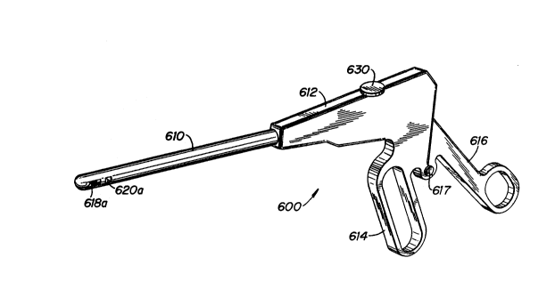
Turning to the first embodiment of the reloadable
instrument, and more particularly to Figs. 22-25, instrument
600 includes elongated housing portion or tubular body 610
and handle assembly 612 having a stationary grip portion 614
and a movable handle 616 pivotally mounted thereto by pivot
pin 617.
The distal end portion o~ elongated housing
portion 610 is similar to the elongated tubular body 16 of
Figs. 1-3 in that it includes a pair of needles mounted on
carrier arms and an inner elongated rod cooperating with the
gear members mounted on the carrier arms. Cut-out portions
618A and 620A are identical to cut-out portions 30B and 48B ~ -
of Fig. 2, respectively, and the actuation of the carrier
arms, i.e. deployment and subsequent latching of the needles
within the housing, occurs in an identical manner.
Therefore, these ~eatures will not be discussed in detail
again. However, the mechanism for actuating the inner
elongated rod in Figs. 22-25 differs from that of Figs. 1-3.
The proximal end portion of the inner elongated rod
¦ terminates in a plurality o~ teeth 624. These teeth 624
cooperate with gear 626 which is lnterposed between teeth
624 and teeth 628 on handle 616. Thus, movement of handle
616 towards handle 614 rotates gear 626 counterclockwise
which moves the elongated inner rod from its proximal
position of Fig. 24 to its distal position shown in Fig. 25.
This deploys the carrier arms and moves the needles into
engagement with the latch member as described in detail
above with respect to Figures 1-3.
When the handle 616 is released, the inner
elongated rod returns to its proximal position (Fig. 24) and
carrier arms return to their retracted positions within the
elongated housing portion 610, leaving the needles latched
-14-
! ` ` ~ i
in the latch member (see e.g. Fig. 11). The suturing
instrument is pulled out of the trocar incision, causing the ~ -
suture to be pulled through the fascia, and the suture is
grasped and preferably cut away from the needles and tied
off as described above. If the user desires to close
another trocar wound with the instrument, screw 630 is
rotated to release the pressure, i.e. frictional engagement,
of retainer member 632 on elongated housing portion 610.
This allows the elongated housing portion 610 to be pulled
distally and removed from the handle portion of the
instrument. A fresh tubular body 610, having a fresh pair
o~ needles and a suture, (as well as carrier arms, gear
mechanism and the other components as described above) can
then be inserted into the handle portion 612 and secured
` 15 therein by tightening of screw 630 to force retaining member
632 to clamp down on tubular body 610. The instrument is ~ ~-
then ready to be used again, i.e. inserted into the body to
close another trocar puncture wound.
Figures. 26-28 illustrate an alternate embodiment
of the instrument of the present invention having a -
removable/replaceable elongated housing portion. The
instrument 700 includes a tubular handle housing portion
712, a pair of flexible curved handle members 714 and an `~
outer tubular ~ody 710. The tubular body 710 is identical
to the elongated tubular hody 610 o~ Figures 22-26, except
an elongated inner rod 723 has a proximally positioned
circumferential recess 716 (instead of teeth) dimensioned to ~;
receive lever arms 718. A pair of compression rings 725 are
provided within housing portion 712 to help retain the
tubular body 710.
In use, squeezing handles 714 towards tubular
handle housing portion 712, causes pins 719 to slide
proximally in slots 720 and lever arms 718 to pivot
clockwise. The engagement of the fingers 721 of lever arms
718 in recess 716 forces the inner elongated rod 723
distally (Fig. 28) to deploy the carrier arms and needles as
.. .:
-15- ~
.: ,.
:: ".'
3 9
described above. After use, the handles 714 are released,
thereby springing back to their original position ~Fig. 27) -
and returning the elongated inner rod 723 to its initial
position. To remove outer tubular body 710, it is rotated
so upper and lower slots (not shown) formed in inner rod 723
are aligned with the finger 721 of each lever arm 18, and
then pulled distally away from handle housing portion 712.
A fresh tubular body with fresh needles and suture can then
be inserted.
Figures. 29-36 illustrate an alternate handle `
design for actuating the inner rod. Instrument 800 includes
elongated tubular handle housing 812, outer tubular body
810, and push button 814 for actuating the elongated inner
rod 827. Except for the slot arrangement 818 described
below, the outer tubular body 810 and the components
contained therein are identical to that described in
reference to Figs. 22-26. Slot arrangement 818, which
provides a bayonet type mount, includes a distal recess 820
and a proximal recess 822. Push button 814 is biased
outwardly through handle housing 812 by spring 816.
Projection 824 of push button 814 is adapted to cooperate
with proximal recess 822. Projection 826 of tubular housing
812 cooperates with distal recess 820 to prevent distal
movement of outer tubular body 810.
In operation, when push button 814 i5 pressed
inwardly, from the position of Fig. 35 to the position of
Fig. 36, projection 824 forces the elongated inner rod 827
distally to actuate the needle carriers and needles as
described in detail above. After use, button 814 is released
allowing inner elongated rod 827 to return to its initial
proximal position of Fig. 35. To remove outer tubular body
810 to allow replacement with a fresh needle and suture
arrangement, tubular body 18 is rotated so that projection
824 of button 814 and projection 826 of tubular housing 812
are in alignment with elongated slot 818. Tubular body 810
can then be removed and a new tubular body initially
-16-
3 : :
~.
inserted so that elongated slot 818 aligns with projections
824, 826 and then rotated so the projections 824, 826 are
positioned within recesses 822, 820 respectively.
It should be understood that the embodiments of
Figs. 22-36 may optionally include a suture tension member,
a retaining mechanism to retain the needle carrier in the
-
partially deployed position, a needle skewing mechanism -~
and/or an indicator to inform the user that the needles are
securely latched.
While the invention has been particularly shown --
I and described with reference to the preferred embodiments,
! it will be understood by those sXilled in the art that
¦ Various modi~ications and changes in form and detail may be
made therein without departing from the scope and spirit of
the invention. Accordingly, modifications such as those
~ -
suggested above but not limited thereto, are to be
considered within the scope of the invention.
,~
;"". ~ ,.
,. ~.,
, ~'.~''
-17-
. ..
. , , . -~.