Note: Descriptions are shown in the official language in which they were submitted.
-
-- 1 --
METHOD AND APPARATUS FOR R~llON
OF OPTICAL COl_u~lCATION SYSTEM IMPAT~M~TS
Fiel~ of ~h~ Tnv~nt;on
The present invention relates generally to the field
of optical communications systems, and particularly to
methods and apparatus for reduction of system impairments
including interference noise and stimulated Brillouin
scattering in lightwave transmission systems, such as
those utilized for transmitting cable television signals.
Backgro1~n~ of ~h~ TnV~nt; on
Community antenna television (CATV) signals used for
cable television transmission may be transmitted over
optical communication networks, using intensity-modulated
analog lightwave signals. Lasers are typically employed
to generate the light signals. A CATV signal generally
consists of several carrier signals representing different
television channels. The analog lightwave systems used
for transmitting these CATV signals have stringent
carrier-to-noise ratio (CNR) and distortion requirements.
A source of noise referred to as interferometric
intensity noise (IIN) can degrade the CNR, thereby
compromising system performance. IIN is caused
predominantly by multipath interference (MPI), which is
interference that results from multiple reflections of the
lightwave signal in optical fiber. In particular, MPI is
detrimental to analog lightwave systems because it
converts source phase noise to lightwave intensity noise,
which increases the system noise level. For a further
discussion of MPI, see Judy, "Intensity Noise from Fiber
Rayleigh Backscatter and Mechanical Splices," Proc. 15th
European Conf. Optical Communications (Gothenburg, Sweden,
September 10, 1989). The spectrum of the noise caused by
IIN is strongly dependent on the optical spectrum of the
modulated laser. Lasers exhibiting relatively broad
-- 2
linewidths produce phase noise that falls within the CATV
signal band. Consequently, IIN in systems employing such
lasers can degrade signal quality.
Interference noise may also be caused by single
reflections of bidirectional light transmission, referred
to herein as single reflection noise, which may occur in
interactive CATV applications. In bidirectional systems,
light travels in both directions along the optical fiber.
If light originating at one end of the system is
reflected, then the reflected light may interfere with the
light originating from the other end of the system.
Because of this interference, the optical frequency
differences between the light from the two sources are
converted to intensity noise. When the light sources'
optical frequencies are close this noise may fall within
the frequency band of interest, thereby degrading system
performance.
MPI noise and single reflection noise within the CATV
band may be reduced by distributing the total noise
spectrum over a broader frequency range. It is known that
by increasing the spectral width of the laser used to
transmit the optical signals, the noise concentration due
to IIN may be spread over a wide range of frequencies.
See Judy, supra. Consequently, broadening the ~ptical
spectrum of the transmitting laser reduces the
concentration of IIN at the frequencies within the CATV
signal band.
In the past, transmission systems using direct
intensity-modulated semiconductor lasers relied on the FM
efficiency of the lasers, also known as chirp, to broaden
the optical spectrum. Darcie, et al, "Fiber-Reflection-
Induced Impairments in Lightwave AM-VSB CATV Systems," 9
J. Lightwave Tech. 991 (1991). Chirp is known in the art
as the incidental modulation of the light's wavelength or
frequency that occurs during direct intensity modulation
of a light source. Chirp resulting from direct modulation
by an amplitude modulated-vestigial sideband format (AM-
VSB) CATv signal can broaden the optical spectral width,
thereby reducing the noise caused by MPI.
Not all of the effects of chirp, however, are
beneficial. Detrimental effects caused by the interaction
of chirp and polarization-mode dispersion (PMD) or
chromatic dispersion in the fiber increase as the
frequency of the modulation increases. CATV signals are
carried at frequencies up to 500 MHz or more. As a
result, the use of chirp produced by CATV signals can
cause an unacceptable level of signal degradation due to
chirp-related impairments. See Phillips, et al, "Non-
linear Distortion Generated by Dispersive Transmission of
Chirped Intensity-Modulated Signals," 3 IEEE Photonic
Tech. Letters 481-83 (1991). This forces the system
designer to strike a delicate balance between too much
chirp, where dispersion creates problems, and not enough,
where multipath interference limits system performance.
An alternative proposal to broaden the optical
spectrum is to employ a fast phase modulator in the
optical transmission system. See Yariv, et al., ~A
Reduction of Interferometric Phase-to-Intensity Conversion
Noise in Fiber Links by Large Index Phase Modulation of
the Optical Beam," 10 J. Lightwave Tech. 978-981 (July
1992). Although this method can lower the noise due to
MPI, this method has the disadvantage of requiring the
incorporation of a fast phase modulator, which
significantly increases the cost of the system.
~Ary of 1-he Tnv~nt; ~n
The present invention provides a method of reducing
interference noise by broadening the optical spectrum
without unduly increasing dispersion impairments in an
optical communications system. The method comprises
r~
- modulating or ~'dithering" the optical signal frequency to
broaden the optical spectrum. This is accomplished by
applying a low frequency signal to the optical source in a
manner that modulates the light source output frequency. By
using a low modulation frequency, typically between 1 kHz
and 100 kHz, and large optical frequency excursions, the
optical spectrum can be broadened so that the MPI noise is
reduced. While the method according to the present
invention may also result in increased distortion, the
distortion it produces is spectrally different than that of
the prior art and results in less perceptible signal
degradation.
The optical frequency can be modulated utilizing a
number of different techniques, including, for example,
using thermal tuning means on the laser or direct modulation
of the laser. The invention may be implemented in several
types of systems including those incorporating externally
modulated solid state lasers and either externally modulated
or directly modulated semiconductor lasers.
The present invention not only reduces the interference
noise in a system, but reduces stimulated Brillouin
scattering by broadening the optical spectrum.
In accordance with one aspect of the present invention
there is provided a method of reducing the noise level in an
electrical signal which is modulated on an optical carrier
signal in an optical transmission system, said method
comprising: effecting modulation of an optical carrier
signal generated by an optical signal generator with a first
electrical signal within a first frequency range; effecting
frequency modulation of the optical carrier signal by
applying a second electrical signal to the optical signal
generator, said second electrical signal being within a
second frequency range wherein the second frequency range
does not overlap with the first frequency range;
transmitting said modulated optical carrier signal over an
optical signal transmission line; and effecting detection of
- 4a -
the optical carrier signal to produce an electrical signal
having a noise level reduced by said frequency modulation.
In accordance with another aspect of the present
invention there is provided a system for transmitting
electrical signals using a lightwave carrier signal
comprising: a) light signal generating means, the light
signal generating means comprising a laser, means for
modulating the laser with a first electrical signal, and
means for frequency modulating of the laser; b) a first
electrical signal generating means for generating a first
electrical signal to be transmitted, operably connected to
the modulation means of the light signal generating means;
c) a second electrical signal generating means for
generating a second electrical signal for frequency
modulating the laser, said second electrical signal being of
a lower frequency than the first electrical signal, operably
connected to the frequency modulating means of the light
signal generating means; and d) means for directing and
carrying the lightwave signal operably connected to the
light signal generating means to direct and carry the signal
produced by said light signal generating means.
Brief Description of the Drawinqs
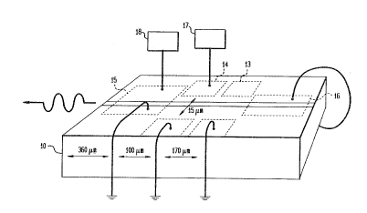
Fig. 1 shows a 1.5 ~m distributed Bragg reflector laser
that is tunable using resistive heating, which may be used
in apparatus and methods according to the present invention.
Fig. 2 shows an optical transmission system employing
the method of broadening the optical spectrum according to
the present invention.
Fig. 3 is a graph of the frequency response of the
optical signal under three different conditions
demonstrating the advantages of the present invention.
. :~
t~
-- 5
De~;le~ Descr; ptinn
The present invention provides a method for reducing
noise in an optical transmission system, such as a CATV
system, by applying a low frequency signal to the optical
signal generator in a manner that modulates the optical
output frequency. One embodiment of an optical signal
generator 10 capable of performing the inventive method is
illustrated in FIG. 1.
FIG. 1 illustrates a 1.5~m distributed Bragg
reflector (DBR) laser 10 that may be frequency tuned by a
thermal tuning means comprising a resistive heater. The
DBR laser 10 is a semiconductor laser having various
control sections including a Bragg section 13, a phase
control section 14, and an active section 15. The Bragg
section 13 and phase control section 14 further include a
resistive heater or tuning resistor which may suitably be
a top p-type cladding layer on the semiconductor laser 10.
See Woodward, et al., "A DBR Laser Tunable by Resistive
Heating," 4 IEEE Photonic Tech. Letters 1330-32 (1992).
The laser 10 also contains a back detector section 16.
The general configuration of a DBR laser for use in an
optical transmission system is well known in the art. For
further details on such a laser, see Woodward, et al.,
supra .
A low frequency signal generator 17 capable of
producing up to a 100 kHz sine wave output is connected to
the phase control section 14 through ohmic contacts
located thereon. Alternatively, the low frequency signal
generator 17 may be connected directly to the active
section 15, as discussed further below. Further, while a
variable frequency generator is described herein, a fixed
frequency source may be employed if single frequency
operation is suited to the environment of operation. For
example, a 1 kHz fixed frequency source may suitably be
used in the embodiment described herein.
-- 6
A high frequency signal generator 18 capable of
producing one or more electrical signals in a first
frequency range, for example, between 5-1000 MHz, but
typically capable of producing CATV signals comprised of
one or more carrier frequencies between 50-500 MHz, is
operably connected to the active section 15 of the laser
10 to effect direct intensity modulation of the laser 10
with an electrical signal to be transmitted. In an actual
transmission signal, generator 18 would be replaced by a
CATV signal source. The back detector section 16 and
Bragg section 13 are configured in a manner well-known in
the art to enable the laser 10 to generate and transmit
1.3~m or 1.5~m lightwave signals.
In operation, generator 18 produces a first
electrical signal to be transmitted, which may suitably be
between 5-1000 MHz, but in a current CATV transmission
application would comprise one or more electrically
multiplexed 50-500 MHz carrier signals. The first
electrical signal is intensity modulated onto the
lightwave carrier by modulating the active section 15 of
the laser 10 of FIG. 1. Alternatively, the laser 10 may
be modulated externally as is well known in the art. The
low frequency signal generator 17 produces a second
electrical signal, herein referred to as the di~her
signal, which frequency modulates the DBR laser 10 in the
manner described herein. The dither signal, which may
suitably be a one volt, 1 kHz sinusoid or other periodic
signal, is applied across the resistive heater in the
phase control section 14 of the DBR laser 10. Because the
phase control section 14 contains a resistive heater, the
temperature of the phase control section 14 of DBR
laser 10 will rise when a voltage is applied thereto. As
the temperature changes, the frequency of the generated
optical signal changes. Consequently, the application of
-
-- 7
a sinusoidal dither signal will cause both the temperature
and the optical frequency of the laser to modulate.
For a DBR laser such as the DBR laser 10 of FIG. 1, a
dither signal amplitude of one volt is generally
sufficient to produce approximately a 2 GHz excursion in
the optical carrier frequency. It will be understood that
the dither signal amplitude and frequency are specified by
way of example only. The dither signal frequency may vary
for the particular application or embodiment as will be
discussed further below, but should be within a range
outside the frequency band of the electrical carrier
signal bandwidth. Typically, the dither signal frequency
will be below the carrier signal bandwidth. Likewise, the
dither signal amplitude that is required to produce a
specific excursion in optical carrier frequency may vary
for the particular application, and is dependent on the
tuning characteristics of the laser. The determination of
such characteristics is a relatively simple matter for one
skilled in the art. See, for example, Woodward, et al.,
supra .
FIG. 2 shows a lightwave transmission system in
accordance with the present invention. A tunable laser 21
having a frequency tuning means, which may suitably be the
thermally tunable DBR laser 10 as described in ~onnection
with FIG. 1, is operably connected to a low frequency
signal generator 22 and a high frequency signal generator
23. In a commercial embodiment of the present invention,
the laser 21 may alternatively be any laser incorporating
a tuning means, such as a distributed feedback (DFB) laser
or an yttrium-aluminum-garnet (YAG) laser. These
embodiments are discussed further below. The tuning means
may suitably be a resistive heater incorporated onto the
laser 21 or an acousto-optic frequency modulator following
the laser 21. The use of an acousto-optic frequency
modulator for tuning a laser is well known in the art.
a ~
-- 8
The high frequency signal generator 23 produces a
first electrical signal, which may suitably be a CATV
signal, to be transmitted which intensity or phase
modulates the tunable laser 21. The low frequency
generator 22 produces a second electrical signal that
frequency modulates the tunable laser 21. The frequency
of the second electrical signal is lower than the lowest
frequency of the first electrical signal bandwidth. The
tunable laser 21 produces at its optical output an
intensity modulated and frequency modulated optical
signal.
The optical output of the tunable laser 21 is
operatively coupled to a lensed tip fiber 24 which may be
on the order of 1 meter in length. The other end of the
lensed tip fiber is connected to the input of an optical
in-line isolator 25. The in-line isolator 25 operates to
prevent the optical signal from reflecting back into the
laser 21. Alternatively, the in-line isolator 25 and
lensed tip fiber 24 may be replaced by an isolator which
is directly connected to the laser 21 as is common in
commercial laser packages. For example, an AT&T 257-type
DFB laser package incorporates an isolator. Such a laser
would of course require the addition of a resistive heater
as discussed further below.
The output of the optical isolator 25 is connected to
one end of a length of optical fiber 26 which may suitably
be on the order of 20 km. In operation, the optical
signal travels through the lensed tip fiber 24, the in-
line isolator 25, and the length of optical fiber 26 to an
optical signal detector 27 that is connected to the- other
end of the fiber 26. The optical signal detector 27
reproduces a signal similar to the first electrical signal
produced by the high frequency generator 23. The optical
signal detector is operably connected to signal receiving
means 28. In one embodiment, the signal receiving means
- 9
28 may comprise a means for demultiplexing a CATV signal,
a means for demodulating one or more of the demultiplexed
50-500 MHz carrier signals, and a means for viewing or
recording the demodulated video signal. Alternatively,
the signal receiving means 28 may be connected to further
optical or electrical transmission means.
In an alternative embodiment of the invention, the
laser 21 of FIG. 2 may suitably be a DFB laser. DFB
lasers are semiconductor lasers commonly employed in
commercial lightwave systems. A DFB laser may readily be
adapted to include a tuning means, such as a thermal
tuning resistor or an acousto-optic frequency modulator.
For an example of a DFB laser incorporating a thermal
tuning resistor, see Sakano, et al., "Tunable DFB Laser
with a Striped Thin-Film Heater," 4 IEEE Photonic Tech.
Letters 321-23 (1992). A dither signal as described above
would then be applied across the tuning of the DFB laser
in a similar manner as it is applied in the case of the
DBR laser illustrated in FIG. 1. Intensity or phase
modulation of a DFB laser by a high frequency signal,
which may suitably be a CATV signal, is well known in the
art.
The method of the present invention could enable the
deployment of CATV systems operating at 1.55 microns which
have heretofore been impracticable without compensation of
dispersion induced distortion. At present, high-chirp DFB
lasers have been operating in 1.55 micron systems, but
require extensive dispersion distortion compensation. In
the art, 1.55~m distributed feedback (DFB) lasers with low
chirp are currently being developed for analog systems so
that systems can transmit signals at both 1.55~m and
1.3~m. See Cebulla, et al, "1.55-~m Strained Layer
Multiple Quantum Well DFB Lasers with Low Chirp and Low
Distortions for Optical Analog CATV Distribution Systems,"
Conf. Lasers and Electro-Optics (Baltimore, Md., May 5,
- 10 -
1993). The implementation of CATV systems using low-chirp
1.55 micron lasers, however, has been limited to date
because such systems are presently incapable of
maintaining a commercially acceptable CNR, due primarily
to IIN. If a 1.55~m low-chirp DFB laser is outfitted with
a thermal tuning resistor and dithered according to the
present invention, the IIN problem could be improved. As
a result, low-chirp DFB 1.55~m lasers may now feasibly be
employed in AM-VSB CATV systems.
Furthermore, the development of interactive video
will increase the need for interference noise reduction.
Interactive video applications employ bidirectional
transmission, which introduces a source of interference
caused by single reflections. In particular, single
reflections of one laser may interfere with direct
transmissions of a laser transmitting the opposite
direction on the same fiber. The method of the present
invention may substantially enhance the development of
such systems by reducing the added interference noise.
In another embodiment of the invention, the optical
frequency in the DBR, DFB or other semiconductor laser may
be dithered by modulating the laser's active section. In
other words, the dither signal could be applied to the
same section of the laser as that to which the ~igh
frequency electrical signal is applied. Due to the
thermal characteristics of the laser semiconductive
material, the FM efficiency exhibited by semiconductor
lasers at low frequencies is much larger than the FM
efficiency in the CATV band. It is therefore possible to
broaden the optical spectrum of even a low-chirp laser by
applying a low frequency signal to its active section.
Dither frequencies of up to 100 kHz may suitably be used.
The advantage of this embodiment of the present
invention is its applicability to existing DFB laser
systems. DFB lasers in current commercial use generally
g
do not contain the incorporated resistive heaters required
for the method of temperature modulation described above
in connection with FIG. 1. Because the direct application
of the dither signal to the laser active section does not
require a resistive heater, the existing systems may
employ the method of the present invention without
retrofitting or replacing the existing DFB lasers. Direct
modulation of the active section with the low frequency-
dither, however, requires a larger intensity modulation
depth than that required when modulating the temperature
as discussed in connection with FIG. 1. It has been shown
that a DBR laser dithered by modulating the resistive
heater on the phase control section requires a modulation
depth of m = 0.1~ to produce a frequency excursion of 0.6
GHz. To obtain the same frequency excursion by directly
modulating the active section, a modulation depth of m =
1~ is required. Because significantly less modulation
depth is required, frequency modulation through a thermal
tuning means is preferable for implementation in new
systems.
A further embodiment of this invention may be used in
optical systems employing externally modulated lasers.
Instead of modulating the high frequency signal, for
example a CATV signal, onto the active section ~f the
laser, the laser may be externally modulated. It is well-
known in the art to externally modulate both semiconductor
lasers, for example, a DFB or DBR, and solid state lasers,
for example, a YAG. The application of the dither signal
does not change for externally modulated systems. A YAG
laser may then be dithered via a resistive heater as
discussed above and the semiconductor lasers may be
dithered through any of the above described methods.
For all of the above-described embodiments, it is
important to apply a dither signal of appropriate
amplitude and frequency. Accordingly, the theory and
'
- 12 -
method for choosing the proper dither signal are discussed
below. Initially, it is important to understand generally
the MPI phenomenon that causes IIN.
MPI is caused by double reflections of a light
signal, one backwards and one forwards, in optical fiber.
Because of MPI, one portion of the light signal can travel
directly through the optical fiber to a detector while
another portion is twice reflected before it reaches the
same detector. As a result, the arrival of the doubly-
reflected portion at the detector is delayed with respectto the unreflected signal. IIN is the noise that results
from the simultaneous arrival of direct input signals and
doubly-reflected signal-s at the optical detector.
The coincidental arrival of a direct signal and a
doubly-reflected signal results in the generation of noise
concentrated at the difference in optical frequency, or
beat frequency, between the two signals. The sum of the
noise caused by the continuous generation of these beat
signals tends to concentrate at frequencies within the
CATV spectrum.
The dither signal, applied according to the present
invention, varies the laser's optical frequency, which
spreads the noise due to MPI over a broad spectrum. In
other words, the dither signal serves to diffus the
concentration of the beat signals. Consider a system
transmitting a 50-500 MHz carrier signal on optical fiber
in which the input light interferes with a reflected light
delayed by a time ~. Theoretically, the objective is to
vary the laser frequency by more than 500 MHz in the time
period r. If this is accomplished, the two signals will
differ in optical frequency by more than 500 MHz, and the
beat signal that would have otherwise added to the noise
concentration below 500 MHz will be moved to a higher
frequency. Consequently, it is desirable to vary the
' -
- 13 -
laser frequency by a relatively large amount to distribute
the noise to higher frequencies.
Ideally, the optical frequency should be varied by an
amount sufficient to cause the beat frequency between the
input light and the doubly-reflected light delayed by a
time ~ to occur outside the signal frequency band. For
example, in a CATV system wherein the frequency band is
50-500 MHz, the optical frequency should constantly be
changed by more than 500 MHz for every time period ~.
However, it is impossible to increase or decrease the
optical frequency indefinitely. Accordingly, the present
invention dithers the optical frequency using a bounded
signal, for example, a sinusoid or other periodic signal.
The optical frequency, fopt, under the influence of a
sinusoidal dither signal, may be expressed: fopt = fopt o +
dfoptcos (Qt), where dfopt is the magnitude of the optical
frequency excursion and n is the dither signal frequency.
Because the optical frequency changes by the quantity
dfoptcos(Qt), the beat frequency between the incident beam
and the doubly-reflected beam at a time ~ later becomes:
df = (dfOpt~2-2cos(Qr) ) cos(Dt) . For a small n~, this
equation may be simplified as the following approximation:
df = (dfopt Qr) cos(Qt).
The beat frequency, as discussed above, sh~uld be as
large as possible. The beat frequency maximum, however,
is limited by system parameters including dispersion and
degradation of laser output power. These limitations
result from attempting to dither the laser too much in
order to achieve higher beat frequencies. A balance must
therefore be struck between too much dither and too little
dither. It has been found that the maximum of the beat
frequency, df, above, should be at least equal to or
larger than the signal bandwidth. In the case of a 50-500
MHz broadband CATV signal, for example, the maximum df
should ideally be greater than 500 MHz. Consequently,
-
- 14 -
(dfopt Q~) > 500 MHz. In the case of a single carrier
signal, for example, a 77.25 MHz carrier, the maximum df
should be greater than the signal frequency.
Consequently, in the case of a 77.25 MHz carrier, (dfopt
Q~) , 77.25 MHz. The more the dfopt n~ exceeds the
frequency band of interest, the more effective the
reduction of MPI will be. The determination of the
maximum optical frequency excursion, dfopt, the dither
frequency, n, and the time delay, r, caused by a
reflection in the fiber are discussed below.
As discussed above, T iS the time delay between an
input signal and a doubly-reflected signal which arrive
simultaneously at a detector due to MPI. If this
interference is caused by two discrete reflections in the
fiber separated by a length l, then ~ = 2nl/c for a fiber
of a refractive index n. In most analog lightwave
systems, however, the dominant source of MPI is double-
Rayleigh backscatter (DRB), not discrete reflections. See
Judy, 15th European Conf. Optical Communications, supra.
For DRB, there is a distribution of distances between
reflections, but it is reasonable to approximate this
distribution with an effective length: leff = (l/2a) (l-e~
2aZ) where a is the attenuation per unit length, measured
in nepers/km, of the optical fiber and z is the~length of
the fiber. The effective length, leff, may be substituted
for l in the equation for determining the time delay
between input signal and reflected signals, r = 2nl/c.
As discussed above, dfopt is the maximum optical
frequency excursion as illustrated by the equation: fopt =
fopt O + dfoptcos (Qt)- The dither signal amplitude dictates
the value of dfopt. As described above in connection with
FIG. 1, for a thermally tunable laser, the amplitude of
the dither signal dictates the amount of change in
temperature and consequently the change in optical
frequency. The optical frequency excursion, dfopt, and the
- 15 -
dither frequency should be chosen so that the product
(dfopt ~r) is larger than the maximum signal frequency. By
way of example, a 5 GHz half-width-half-maximum frequency
excursion may be accomplished by a dither signal amplitude
of approximately two volts when applied to the phase
control section of a DBR laser such as the one discussed
above in reference to FIG. 1. The relationship between
the dither amplitude and the change in optical frequency
for other lasers may be readily determined by one skilled
in the art.
Consider, for example, an optical system for
transmitting a 77.25 MHz signal configured in a manner
similar to that described above in connection with FIG. 2.
For this example, the optical fiber 26 has a length of
16km, an index of refraction of 1.5, and an attenuation
per unit length of 0.35dB/km. It is assumed that DRB is
the predominant source of IIN. To modulate the light
frequency in a manner adequate to cause the maximum of the
beat frequency between the signal and the doubly-reflected
light to be at least as large as the maximum signal
frequency, a dither signal should be chosen so that (dfopt
Q~) ~ 77.25 MHz.
The time delay T between input signal and the delayed
reflection should first be determined. For ~ =~2nl/c in
this case, l = leff, because DRB, and not discrete
reflections, are the source of noise. As discussed above,
leff = (l/2a)(1-e~2aZ). Where a, the attenuation of the
fiber per unit length, is 0.35dB/km, which translates to
0.08 nepers/km, and the overall length of the fiber, z, is
16km, leff = 6km. If the index of refraction, n, for the
fiber is approximately 1.5, then, the ~ z 0.06 ms.
Given ~ z 0.06 ms, the amplitude and frequency to the
dither signal may be determined. As indicated earlier in
reference to FIG. 1, a dither signal amplitude of one volt
produces an optical frequency excursion, dfopt, of 2.4 GHz.
-
- 16 -
As discussed above in reference to FIG. 1, the
relationship between dither signal amplitude and optical
frequency excursion may readily be determined by one
skilled in the art. If dfopt = 2.4 GHz and I ~ 0.06 ms,
then (dfopt Q~) ~ 77.25 MHz requires that the dither signal
frequency, Q ~ 550 Hz. As a consequence, a one volt, 1
kHz sine wave dither signal applied to the optical signal
generator should substantially reduce the noise
concentration level below 77.25 MHz caused by DRB having
an effective distance between reflections of 6km.
To illustrate the advantages of the present
invention, experimental data was obtained using the
embodiment illustrated in FIGS. 1 and 2. FIG. 3 shows the
optical spectra produced by a DBR laser modulated by a
77.25 MHz signal under three separate conditions which are
depicted by three curves 31, 32 and 33. The data
presented in FIG. 3 was obtained in an experimental
transmission system environment of the kind described
above in reference to FIG. 2 wherein the laser 21 was a
DBR laser such as the laser 10 of FIG. 1, the lensed tip
fiber 24 was 3 meters in length and the length of optical
fiber 26 was 16 km. The bottom curve 31 of FIG. 3, which
has the lowest noise floor, was taken without the 16 km
length of fiber 26 of FIG. 2 present in the sys~em. Under
these ideal conditions, the CNR is primarily limited by
shot-noise from the laser 21 of FIG. 2. The uppermost
curve 32 of FIG. 3 was taken under the conditions as
illustrated in FIG. 2, but without application of a dither
signal. The comparison of curves 31 and 32 reveals that
the addition of the fiber added over 9dB of noise, a
substantial portion of which is due to IIN. In the middle
spectrum 33, a 1 kHz sine wave dither signal had been
applied to the phase-control section of the laser 21 of
FIG. 2 according to the method of the present invention.
5 8
-
- 17 -
The desired portion of the spectrum, the carrier
signal at 77.25 MHz, is illustrated by portion 34 of the
curve 32, and peaks at approximated -20dBm under the test
conditions. Although the resolution in FIG. 3 only shows
one curve having a portion 34, similar portions of curves
31 and 33 are superimposed thereon and have substantially
the same characteristics. The portions of curves 31, 32
and 33 which are at frequencies other than approximately
77.25 MHz represent the power level of undesirable noise,
also called the noise floor. By comparing curve 32 and
33, it is clear that the dither signal significantly
reduced the noise floor.
The noise floor o~ curve 32 ranges from about -77dBm
at 74 MHz to nearly -70dBm as the frequency approaches the
lower limit of the carrier band near 77.25 MHz. The noise
power level remains at -70dBm at frequencies just above
the higher limit of the carrier band and decreases to -
77dBm at approximately 80 MHz. The noise floor on curve
33, however, where the dither frequency was applied,
remained substantially constant at or below -80dBm for the
range between 74 MHz and 80 MHz, not including the carrier
frequency. It can be seen, therefore, that the
application of the dither signal lowered the noise floor
by between 3dB and lOdB at frequencies near the-carrier
frequency.
It should be noted that under the test conditions
discussed above, an increase in noise was observed for a
small frequency band of approximately 0.3 MHz on either
side of the carrier band. It was subsequently determined
that this noise was due to discrete reflections at the
coupling between the laser 21 and the lensed tip fiber 24
and the coupling between the in-line isolator 25 and the
lensed tip fiber 24. As discussed above in connection
with FIG. 2, commercial laser packages usually consist of
a laser connected directly to an optical isolator, thus
,.~
- 18 -
eliminating this particular source of noise. Later
experimentation with a DFB laser package containing an
integral optical isolator confirmed this fact.
Returning to FIG. 3, the reduction in the noise floor
and the resulting improvement in the CNR as illustrated in
FIG. 3 represent a significant improvement to present
analog lightwave systems. As discussed above, analog
optical transmission systems such as those employed to
transmit CATV signals have stringent CNR requirements.
For CATV systems, improvements in the CNR can result in
the delivery of signals with enhanced picture quality to
both receivers of the optical signal and, ultimately,
cable television subscribers. Presently, the highest
achievable CNR of existing 1.3 micron systems is limited,
in part, by IIN due to double-Rayleigh backscatter (DRB).
The techniques discussed above, by providing even a 2-3dB
improvement in the CNR, can now substantially enhance the
quality and performance of existing 1.3 micron CATV
systems.
It should be noted that the slow dither of the
optical frequency will cause distortion when combined with
fiber dispersion. This distortion, however, is spectrally
different than the distortion caused by the prior art
method of using high chirp lasers to broaden the optical
spectrum. The distortion due to the dither signal appears
close to the carrier frequencies as it is due to the cross
product of the carrier signal and the low frequency dither
signal, while the distortion due to chirp appears over a
wider spectrum. It was observed experimentally that in
CATV applications relatively high amounts of distortion
can be tolerated without degrading the video when
employing the technique of the invention. Experimental
observations show that no discernable signal degradation
occurred until the distortion level reaches 30dB below the
carrier signal. Because similar distortion due to chirp
~ '3 5 8
"~
- 19 -
can be no larger than 60dB below the carrier signal before
unacceptable signal degradation occurs, the invention, by
using a low frequency dither to modulate the optical
frequency, provides a substantial advantage.
A further advantage of the present invention is its
ability to reduce stimulated Brillouin scattering.
Stimulated Brillouin scattering (SBS) is an impairment to
lightwave systems using high power transmission.
Consequently, the CNR of high power CATV systems suffer
from SBS. It is also known that by broadening the optical
spectrum of the laser, SBS may be reduced. See, for
example, Mao et al., "Suppression of Brillouin Scattering
In Lightwave AM-VSB CATV Transmission Systems", Optical
Fiber Conference/IOOC, 141-43 (1993). The method and
apparatus of the present invention, by broadening the
optical spectrum, is operable to reduce SBS in high power
lightwave systems.
It is to be understood that the above-described
arrangements of the invention are merely illustrative.
Other arrangements may be devised by those skilled in the
art which will embody the principles of the invention and
fall within the spirit and scope thereof.