Note: Descriptions are shown in the official language in which they were submitted.
2~3~
~.,,
AIR SAVING SLEEVE GUN
~'
. .
This invention relates to seismic source devices and
more particularly to a shuttle controlled seismic source
device which allows only a portion of the compressed air in
the main chamber of the device to be discharged into the
surrounding environment.
In marine seismic exploration, a source of acoustic
energy is released into the water Pvery few seconds to
obtain appropriate acoustic waves that propagate into the
earth's surface. These waves are reflected at interfaces
of the subsurface formations and propagate back to
instruments where transducers convert the acoustic waves to
electronic signals which are recorded and later processed
~J into a record section for interpretation of the subsurface
formations.
In recent times, the major marine seismic energy
sourc~ has been the air gunO These air guns release high
pressure air, typically 2,000 psig to 6,000 psig into the
water to create the desired acoustic wave.
Many conventional air guns comprise an annular housing
;~ 20 that contains means for discharging compressed air through
exhausk ports in the housing. Compressed air is stored
within the housing in a main chamber. The only moving
component (except for the solenoid triggering device) is a
shuttle, which when raised, permits air to escape from the
~5 main chamber through the ports in the main housing into the
surrounding water. The size of the gun is determined by
;~ the main chamber volume selected. By having a constant
,i . . .
~- source of compressed air through an inlet passage in the
housing, the upper chamber containing the shuttle is filled
and forces the shuttle into a sealed position, closing off
all exhaust ports from the main chamber. By using a
solenoid valve to allow air flow beneath the shuttle face
~
,
:,:
.,
rt
.l
- ~32~6~L
and cause an unequal pressure on the shuttle, the shuttle
is accelerated in the upward direction, exposing the
- chamber exhaust ports and allowing compressed air to escape
into the surrounding water~ When the shuttle is in the
"down," or pre-fire position, the air gun is charged and
ready for firing.
Air guns are typically deployed underwater in an
array. When fired, the air guns nearly simultaneously
release compressed air with a velocity at or near Mach 1.
The discharging air from each gun forms a substantially
; spherical bubble having an air/water interface that
translates radially outward from the gun at so~e initial
acceleration. The rapid expansion of the air/water
interface causes the desired compr~ssion wave. The point
' 15 in time when the acceleration of the air/water interface
declines to approximately zero corresponds to the maximum
acoustic pressure generated by each individual gun.
At some instant in time after the maximum acoustic
pressure is reached, the bubble generated by each gun
begins to colli~pse under the pressure of the surrounding
water. The collapsin~ bubble does not collapse
instantaneously, but rather tends to collapse and reexpand
cyclically with a freguency of oscillation that is peculiar
to the particular gun. The oscillatory collapse of the
bubble generates a series of secondary acoustic pulses,
which, if not filtered, obscure the behavior of the
acoustic waves from the first bubblesi.
The sizes of the individual guns are tailored to the
sizes of the other guns in the array so that the amplitudes
of the initial pulses from each gun constructively
int~rfere or add, while the undesirable secondary acoustic
pulses from the oscillatory collapse of the bubbles
destructively interfere.
Experimentation has shown that it is more difficult to
tailor the array of air guns to use destructive
~, ~
. .~
'.;
'!.
~, .
.: .
: '::
~2~
--3--
interference to successfully nullify secondary acoustic
pulses from relatively larger (as opposed to smaller)
bubbles from the air guns. Thus, it is desirable to have
the air guns produce as small bubbles as possible.
When fired, the typical air gun allows 80% to go~ of
the air in the main chamber to be exhausted into the water.
However, as noted above, during the firing sequence of this
type of air gun, the acoustic pressure generated by the air
discharging from the main chamber will rapidly increase to
a maximum and then begin to tail off, shortly after the air
begins to discharge from the main chamber and well before
the main chamber is completely discharged. Thus, any air
discharged from the main chamber after the maximum acoustic
pressure is reached is wasted, and will form another bubble
that will create an undesired pulse.
Large losses of air mass from the main chamber result
in two undesirable effects~ the requirement for
unnecessarily large shipboard compressor equipment; and (2)
the production of large bubbles that may produce secondary
pulses that prove difficult to filter. Large losses of air
~olume from the main chamber require more time and more
air, and thus larger shipboard compressor equipment, to
~ rerharge the air gun between firing cycles.
The prior art contains a number of devices designed to
control the amount of compressed air lost during firing.
These previous designs have utilized a dual shuttle
arrangement wherein the first shuttle is configured to
enable compressed air to escape into the surrounding water,
and the second shuttle is configured ~o close the opening
through which the compressed air is dischar~ed to minimize
the amount of compressed air lost during each firing cycle.
In these devices, typically the second shuttle is activated
by the air discharge flow resulting ~rom the action of the
~, first shuttleO The action of the discharging air flowing
around the second shuttle causPs it ~o close.
-
~,i
'~
_4_ ~ 3~
Due to the unavoidable variations in the air flow
around the second shuttle as a result of surface
imperfections on the second ~huttle, irrPgular kinetic
friction between the second shuttle and the housing, and
the non-linear behavior of air flowing at very high
Reynolds numbers, the closing time for the second shuttle
may vary greatly from one firing cycle to the next. The
~ result is wide variation in the air bubble size that is
; discharged from the gun and the resulting period of
oscillation. Filtering out such variations by use of
destructive interference or other methods has proven
difficult.
' The present invention is directed to overcoming or
minimizing one or more of the problems discussed above.
A seismic source apparatus having a selectively
energizable actuator and a supply of compressed air
includes a housing adapted to receive a charge of
compressed air from the supply of compressed air. A
shuttle is movably retained relative to the housing, and
movable between a first, pre-firing position, and a second,
firing position. The shuttle and the housing cooperatively
define a firing aperture when the shuttle is moved aw~y
from the first position. A shut-off chamber is formed
between surfaces associated with the housing and the
shuttle. The shut-off chamber is operable to receive a
charge of compressed air from the housing to urge the
,~ shuttle to return to its first position after movement to
; the second position. A shut-off passage provides fluid
.:.;
communication between the shut-oEf chamber and the firing
aperture when the shuttle is moved away from the first
position. A water sealing mechanism is movably retained
' relative to the housing and is adapted to prevent ambient
uid from flowing into the shut-off passage when the
shuttle is in its first position.
!,' ~
.,
'~
2~%~ 4
In another preferred embodiment, a seismic source
apparatus having a selectively energizable actuator and a
supply of compressed air includes a housing assembly
adapted to receive a charge of compressed air from the
-~ 5 supply of compressed air. The housing at least partially
defines a main chamber. A shuttle, having a pre-firing
position, is slidably mounted around the periphery of the
i housing and is operable to selectively allow the escape ofcompressed air from the housing when the seismic source
apparatus is fired. A shut-off chamber is formed between
the surfaces of the housing and the shuttle. The shut-off
chamber is operable to receive a charge of compressed air
'~ from the main chamber to urge the shuttle to return to itspre-firing position when the seismic source apparatus is
fired. A shut-off passage couples the shut-o~f chamber
~; with the housing to enable the charge of compressed air toflow into the shut-off chamber when the seismic source
apparatus is fired. A solenoid chamber ls coupled to the
;i housing. The solenoid chamber is adapted to receive
compress~d air from the supply of compressed air, and is
selectively operable to supply the compressed air into the
actuator when the seismic source apparatus is fired to urge
the shuttle to leave its pre-firing position. A water
sealing mechanism is movably retained relative to the
housing and is adapted to prevent ambient liquid from
flowing into the shut-off passage when the shuttle is in
the pre-firing positiôn.
Other advantages of the invention will become apparent
upon reading the following detailed description and
~' 30 references to the drawings in which:
FIG. 1 depicts the seismic source apparatus during the
~! pre-firing sequence, illustrated partially in vertical
i section.
'~ FIG. 2 depicts a close up detail of one portion of the
~' 35 seismic source apparatus, showing the solenoid chamber and
. .,
., ,~
, .
-
, .
~.~
" . .
~3256 ~
the solenoid chamber orifice, illustrated partially in
vertical section.
FIG. 3 depicts a close up detail of one portion of the
seismic source apparatus, showing the water sealing
mechanism, illustrated partially in vertical section.
FIG. 4 depicts a plot of the forces, as a function of
time, exerted on shuttle by the spring chamber and the
'l shutoff chamber of the exemplary apparatus of Fig. 1.
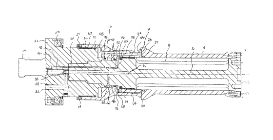
Referring to Fig. 1, therein is depicted an exemplary
preferred embodiment of a seismic source apparatus 10 in
its pre-firing configuration, seismic source apparatus 10
includes a body assembly or housing 12, cap 22, actuator
24, and shuttle 26. Body 12 and chamber sleeve 18
cooperatively form a main chamber 14 that is around center
post 16. The size and specific configuration of main
chamher 14 will depend on the magnitude of acoustic waves
,- required for the particular survey. Chamber sleeve 18
' encloses main chamber 14. Chamber sleeve 18 is coupled to
body 12 by way of bolts 19.
The cap 22 and body 12 are preferably threadably
coupled by the threaded connection between cap 22 and a
threaded portion 20 of body 12. Other connection methods
may alternati~ely be used such as welding. Cap 22 includes
a timing coil 23 adapted to send a signal to a sensing unit
2s (not shown). Sensing unit (not shown) monitors when
seismic source apparatus 10 fires. Monitoring is necessary
i to assure the synchronization of the firing of all of the
air guns in a typical array. The operation of timing coil
- ~ 23 is discussed more fully below.
Actuator 24 is coupled to cap 22. Actuator 24 i5
preferably a co~ventional solenoid actuated valve, capable
of rapidly opening and closing in response to an electrical
signal and capable of withstanding pneumatic pressures as
great as 6000 psig or higher. A preferred type of ac~uator
. .
~,
.
:
~:
:'
2~,32
--7
is the Model SV-3, manufactured by Halliburton Energy
Services Company.
Shuttle 26 slidably encircles portions of body 12 and
cap 22. At one end of shuttle 26, a plurality of permanent
magnets 27 are circumferentially disposed. Magnets 27 are
configured and placed to energize timing coil 23 when
magnets 27 contact cap 22 proximate timing coil 23, as when
shuttle 26 translates toward actuator 24 during firing. At
the other end of shuttle 26 a shuttle face 28 abuts chamber
sleeve 18. A face seal 29 extends around the internal
periphery of one end of chamber sleeve 18 and abuts shuttle
face 28. Face seal 29 is configured to prevent the flow of
compressed air from main chamber 14 past shuttle face 28
when shuttle 26 is in its pre-firin~ position, as shown in
FIG. 1. A chamber sleeve lip 30 extends around the
external periphery of a portion of shuttle 26 adjacent to
shuttle face 28.
As discussed more fully below, when seismic source
1 apparatus 10 is fired, shuttle 26 translates toward cap 22,
2',' 20 and compressed air from main chamber 14 flows past face
seal 29, shuttle face 2~, and chamber sleeve lip 30, and
emanates radially outwardly from body 12 in a 360~ pattern~
ri forming a substantially spherical bubble that generates an
acoustic pressure wave.
i 25 A fill port 32 extends into a fill passage 34 which
,,! extends through cap 22 and threaded portion 20 of body 12,
j terminating within center post 16~ A fill orifice 36
j~; ex~ends from fill passage 34 to main chamber 14 to enable
compressed air to be introduced into fill passage 34 from
fill port 32 to pass into main chamber 14~ Fill passage 3~
is configured to carry a supply of high pressure compressed
.
air, and is connected to a continuously pressurized source
of compressed air ~not sAown).
; Referring now also to FIG.2, in a pref~rred
'; 35 embodiment, seismic source apparatus includes a sol~noid
.
.
.~ ~
':
~~2~
--8--
chamber orifice 38 that is positioned within fill passage
34 and enables fluid communication between fill passage 34
and solenoid chamber 40. As discussed more fully below,
- solenoid chamber orifice 38 and solenoid chamber 40 are
configured to provide a quick burst of high pressure air
through actuator 24 when actuator 24 is opened in order to
start the shuttle 26 in motion, while restricting the flow
of air from fill passage 34 into the actuator 24 so that
the pressure in the main chamber 14 remains high enough to
emit a suitable bubble, and so that a limited air volume
flows from the continuously pressurized compressed air
source (not shown) into firing passage 48 while actuator 24
hangs open.
A secondary passage 42 extends from fill passage 34 to
a circumferential spring chamber 44. Compressed air flows
from fill passage 34 into spring chamber 44 to provide a
.~ force bearing on surface 46 of shuttle 26. The diameter of
- secondary passage 42 is preferably larger than the diameter
i~ of fill orifice 36 to enable spring chamber 44 to
pressurize before main chamber 14 pressurizes so that there
will be a ~;n;mal net opening force exerted on shuttle 26
;. prior to spring chamber 44 reaching full pressurization.
. .
A mechanical spring (not shown) may alternatively be
inserted into spring chamber 44 to provide a force bearing
on surface ~6 of shuttle 26. The spring (not shown) may
a t alone in providing a force against shuttle 26, thus
obviating the need for secondary passage 42.
~lternatively, the spring (not sh~wn) may act in concert
with compressed air that is introduced into spring chamber
:
44 to provide a force against shuttle 26.
' In another preferred embodiment, the secondary passage
;; 42 may be eliminated and the spring chamber 44 filled with
a fixed quantity of inert gas, via a supply port (not
shown)O In such an embodiment, the spring chamber 44 would
behave like a sealed gas spring.
;,.
,: ~
2 ~ 4
g
.
Both the mechanical spring (not shown) and the sealed
gas spring (not shown) have the advantage of providing a
constant closing force on the shuttle 26, independent of
the pressurization of the seismic source apparatus 10. A
seismic source apparatus 10 having either of these types of
springs may be deployed underwater without having to be
pressurized on board ship.
The specific configuration of spring chamber 44 is not
~ critical as long as a sufficient area of shuttle 26
P-ncloses spring chamber 44 such that the force imparted by
; the compressed air or spring (not shown) in the spring
-. chamber 44 on shuttle 26 is sufficient to hold shuttle 26
,i in its pre-firing position during pressurization, and is
~ sufficient to assist in the translation of shuttle 26
! 15 toward chamber sleeve 18 during the firing sequence.
~ . . .
A firing passage 48 extends from actuator 24 through
': cap 22 and the threaded portion 20 of body 12, terminating
within body 12. A firing chamber passage 50 extends from
firing passage 4B to a firing chamber 52. Firing chamber
52 is formed by the suxface 54 on shuttle 26 and the
. surface 56 on body 12. Seals 58 and 60 are
circumferentially disposed between shuttle 26 and body 12
to prevent leaXage of air from firing chamber 52. Wear
~; rings 62 and 63 act as bearings for shuttle 26.
'~ 25 A boost passaga 64 extends from one portion of shuttle
~ face 28 to a point adjacent firing chamber 52 and between
:~ seals 58 and 60. While there are preferably four
: circumferentially spaced boost passages 64, only one is
shown, and for the sake of simplicity, only one is
discussed. At shoulder 65, there is sufficient clearance
between shuttle 26 and body 12 to enable fluid
communication be~ween firing chamber 52 and boost passage
6~. ~s a result of such fluid communication, boost passage
64 is pressurized as soon as actuator 24 opensO As
~: 35 discussed more fully below, when actuator 24 is openedl air
..
~;
~' .
:' -
2~3~
--10--
flows from actuator 24 into firing chamber 52, and as a
result of the above noted fluid communication, in turn,
. flows from firing chamber 52 into boost passage 64,
providing an additional opening force on shuttle 26. When
- 5 shuttle 26 begins to translate away from face seal 29, air
' from main chamber 14 will flow into boost passage 64
~ providing an added opening force on shuttle 26.
A shut-off passage 66 is shown extending from shuttle
face 28 to a shut-off chamber 68 that is circum~erentially
disposed between shuttle 26 and cap 22. While there are
preferably four circumferentially spaced shut-off passayes
66, only one is shown, and for the sake of simplicity, only
one is discussed. The exact configuration of shut-off
,
chamber 68 is not critical as long as bearing surface 69 of
shuttle 26 is suffi~iently large su~h that compressed air
flowing from main chamber 14 into shut-off chamber 68 will
exert sufficient force on shuttle 26 to accelerate it
,. .
. toward chamber sleeve 18 after the firing sequence.
' Seals 70 and 72 are circumferentially disposed between
shut'tle 26 and cap 22, and on either side of shut-off
chamber 68 to prevent the leakage of air to or from shut-
off chamber 68 and spring chamber 44.
' Referring now also to FIG. 3 which shows a detailed
.'''! view of the interface between shuttle face 28, face seal
' 25 29/ and chamber sleeve lip 30, experiment has shown that i~
. .:
.; ambient water is allowed to flow past chamber sleeve lip 30
.;
.; and enter shut-off chamber 68 when seismic source apparatus
; lO is in its pre-firing position, seismic source apparatus
10 will fail to operate properly after a firing a few
. 30 times. Accordingly, a water sealing mechanism 74 is
. positioned adjacent face seal 29 to prevent ambien-t water
from flowing past chamber sleeve lip 30 and entering shut-
'~'. o~f chamber 68 when seismic source apparatus 10 is
; submerged and in its pre-firing position. Water sealing
i: 35 mechanism 74 includes a sealing ring 76 that is slidably
';:
~.:
. .
: .
'~:
;,
~2~ ~
--11--
disposed around the periphery of chamber sleeve 18, an O-
ring 78 disposed about the periphery of the shuttle outside
diameter edge 80 and within peripheral channel 81, and a
plurality of biasing members or peripheral springs 82
circumferentially disposed within chamber 84.
Sealing ring 76 is composed of a first ring 86 and a
second ring 87 that are bolt connected by bolts 88. There
are preferably eight bolts 88 spaced peripherally about
sealing ring 76. Sealing ring 76 will have range of
sliding motion toward and away from actuator 24 that is
limited in one direction by stop 9o, and in the other by
stop 92. The range of sliding motion preferred for sealing
ring 76 is normally quite small, and may be as small as
0.020 inches. It should be noted that chamber sleeve lip
30, as noted above, is actually preferably part of sealing
ring 76.
' 0-ring 78 is disposed within dove~tailed channel 81and provides th~ primary seal from ambient water pressure.
A vent 96 extending from channel 81 to the exterior of
sealing ring 76 vents pressure to prevent O-ring 78 from
being pushed out of channel 81 when seismic source
' apparatus 10 is fired.
Peripheral springs 82, while shown and described as a
plurality of coil springs for simplicity of illustration,
may also comprise either a plurality of spring washers or
wave springs. Peripheral springs 82 are configured to bias
sealing ring 76 towards shuttle face 28 to compress G-ring
r 78 against shuttle outside diameter edge 80. Air pressure
' from shut-off chamber 68 and main chamber 14 is prevented
from laaking around peripheral springs 82 and bolts 88 by
0-ring 91.
The water sealing mechanism 74 is intended to operate
as ?a relief valve which seals shuttle face 28 from ambient
water while allowing internal air pressure to vent. If
water sealing mechanism 74 fails to vent internal air
,:
. . ~ ~
~ ~2~
-12-
pressure, such trapped pressure might prevent shuttle face
28 from seating against face seal 29.
; The operation of the seismic source apparatus lO may
be divided into two operations, the pre-firing sequence,
and the firing sequence. FIGS. 1-3 show the configuration
of seismic source apparatus 10 during the pre-firing
sequence. High pressure air, normally 2000 psig, or
greater, is supplied to seismic source apparatus lO through
fill port 32. The compressed air passes through fill
passage 34, solenoid chamber orifice 38, and through
secondary passage 42 and fill orifice 36, pressurizing
spring chamber 44, solenoid chamber 40, and main chamber
14. The air pressure and/or spring (not shown) in spring
; chamber 44 provides a force against shuttle 26 which moves
shuttle 26 toward chamber sleeve 18, and compresses shuttle
face against face seal 29, sealing main chamber 14.
. .
Typically, after a few seconds of flow through fill port
32, main chamber 14, spring chamber 44, and solenoid
chamber 40 are pressurized to the ~ull system pressure, and
seismic source apparatus lO is ready for the firing
sequence. At this point, s~aling ring 76 is biased against
shuttle 28 face by peripheral springs 82, thereby sealing
shut-off chamber 68 from the ambient water pressure
surrounding seismic source apparatus 10.
- 25 At the outset of the firing sequence, actuatox 24 is
. .
energized. A quick burst of air flows from solenoid
chamber 40 through actuator 24, through firing passage ~8
and firing chamber passage 50, and into firing chamber 52.
The air pressure within firing chamber 52 provides a force
~ 30 bearing on surface 56 of shuttle 26 in the direction of
'' actuator 24. While the pressure is approximately the same
in both spring chamber 44 and firing chamber 52, the force
acting on surface 54 of shuttle 26 is greater than th~
~' force exerted on shuttle 26 by the spring chamber 44 since
the area of shuttle 26 exposed to firing chamber 52 is
!' .
',.~'
:,-,,
.'.,
'''~
','
~ ~ 3 ~
greater than the area of shuttle 26 that is exposed to
spring chamber 44. In addition, air flows from firing
chamber 52 through boost passacJe 66 and across shuttle face
28 to provide an additional opening force.
The following description of the operation and
preferred dimensional ratios of the seismic source
s apparatus lO is based to some extent on computer modelling.
As noted above, solenoid chamber 40 is configured to
hold a small volume, high pressure, charge of air that is
sufficient to start the shuttle 26 toward actuator 24.
Solenoid chamber orifice 38 is configured to throttle air
flowing ~rom fill passage 34 and main chamber 14 into
solenoid chamber 40. Since actuator 24 will have a
j tendency to hang open for approximately forty to fifty (40-
;~ 15 50) milliseconds due to the residual magnetism in the
actuator 24, while the shuttle 26 will typically open and
close after approximately fourteen (14) milliseconds, any
" air flowing from fill passage 34 and main chamber 14 into
actuator 24 after shuttle 26 closes will prevent shuttle 26
from closing. The purpose of solenoid chamber 40 and
particularly solenoid chamber orifice 38 is to minimize the
- air flow from fill passage 34 into actuator 24 while
actuator 24 hangs open.
In one preferred embodiment, the problem of shuttle 26
being held open as a result of residual magnetism is solved
by use of solenoid chamber orifice 38 and solenoicl chamber
40. In another preferred ambodiment, the residual
magnetism probl~m may be solved by placing a non-magnetic
spacer ~not shown) between the plunger (not shown) and the
bocly of actuator 24. In still another preferred
embodiment, the residual magnetism problem may be solved by
use of a shipboard polarity reverser (not shown) to
selectively reverse the polarity of actuator 24. In such
alternate embodiments, seismic source apparatus lO need not
',,
. . .
.
~ ~ 3 2 ~
-14-
include a solenoid chamber orifice 38 and sol~noid chamber
40.
Almost instantaneously after shuttle 26 begins to
translate toward actuator 24, air from main chamber 14
begins to flow through boost passage 64 and into firing
. chamber 52. In addition, air pressure from main chamber 14
acts against shuttle face 28 and that portion of shuttle 26
~hat is circumscribed by chamber sleeve lip 30. Thus, the
combination of the air pressure acting on the firing
.~ 10 chamber 52 from firing chamber passage 50 and boost passage
64; and the air pressure acting on shuttle face 28, combine
to rapidly accelerate shuttle 26 toward actuator 24. Air
. escaping from main chamber 14 also acts against sealing
~ ring 82 to translate it away from shuttle face 28, thereby
.~ 15 decQmpressing O-ring 78 and thereby remove the seal between
~; shuttle face 28 and the ambient water pressure. Sealing
.' ring 76 is translated to stop 88 and held ther~ by the
. pressure of the air escaping from main chamber 14.
As shuttle 26 moves away from face seal 29, air from
main chamber 14 flows outward through the 360~ opening
!, between chamber sleeve lip 30 and shuttle face 2%. At the
~~ point when shuttle 26 clears chamber sleeve lip 30, shuttle
26 is undergoing rapid acceleration toward actuator 2~. As
shuttle 26 clears chamber sleeve lip 30, the high pressure
air from main chamber 14 flows into the surrounding water)
. forming a nearly spherical bubble that generates the
.'~ desired acoustic pressure wave.
A Almost instantaneously after shuttle 2~ begins to
;~ translate toward actuator 24, compressed air from main
~: 30 chamber 14 begins to flow through shut-off passage 66 and
;, into shut-off chamber 68. The air pressure in shut off
chamber 68 provides a force acting on shuttle 26 in the
direction of chamber sleeve 18. As the air pressure from
main chamber 14 declines during the firing sequence, the
~; 35 combined forces exerted on shuttle 26 by spring chamber 44
.:
,,
:
,,
,
,. ~.
~ ~ 32~ ~ -15-
and shut-off chamber 68 exceed the forces applied on
shuttle 26 via the air pressure acting on firing chamber 5~
and shuttle face 28. As a result, shuttle 26 is -translated
toward, and seated against, chamber sleeve 18 before all of
the air mass in main chamber 14 is exhausted.
~; At the conclusion of the firing sequence, the shuttle
26 will typically not remain seated against chamber sleeve
, 18, but rather, will have a tendency to bounce open one or
- two times until the pressure in main chamber 14 has fallen
sufficiently such that the combined pressures in spring
chamber 44 and shutoff chamber 68 are sufficient to keep
shuttle 26 seated against chamber sleeve 18. However, each
time shuttle 26 bounces open after the firing sequence, air
mass from main chamber 14 is uselessly lost to the
surrounding water. This is due to the fact that spring
chamber ~4 loses the majority of its pressurized air mass
on the initial return stroke of shuttle 26. Therefore, it
'':
is important to provide a secondary source of force to urge
shuttle 26 to abruptly close during subsequent return
strokes. Shut-off chamber 68 and shut-off passage 66 act
' as such a secondary source of force to act in union with
spring chamber 44.
~ Referring now to FIG. 4 which shows a plot of the
; forces exerted on shuttle 26 by spring chamber 44 and
shutoff chamber 68 for a preferred embodiment of seismic
s~urce apparatus 10, it is evident that during the initial
return stroke of shuttle 26, represented by the 5.4
millisecond point 98 on the time axis, the dominant closing
force is provided by spring chamber 44, however, after the
shutt1e bounces open and begins its second return stroke,
,.
represented by the 8.5 millisecond point 100 on the time
axis, the dominant closing force is provided by the shutoff
chamber 58.
.,
':.
, .
. .i
:.
: ..
:: .
16 ~3~6~
-
As noted above, the entire firing sequence typically
lasts approximately fourteen (14) milliseconds. The air
flowing past chamber sleeve lip 30 approaches sonic speeds~
After shuttle 26 has closed, the air supply to shut-
off chamber 68 is cut off. Any air volume remaining within
shut-off chamber 68 will bleed of~ into the surrounding
water by passing the clearances between shuttle face 26, O-
ring 78, and chamber sleeve lip 30. When the remaining air
volume within the shut-off chamber 68 has bled off,
peripheral springs 82 bias sealing ring 76 toward shuttle
face 28 to again compress O-ring 78 and provide a seal from
ambient water pressure. The seismic source apparatus lO is
then ready for the next firing.
By careful selection of the ratios of various
dimensions of the seismic source apparatus 10, shuttle 26
may be closed during the firing sequence just after the
' maximum acoustic pressure is generated, thus: (1) saving a
minimum of approximately 50% of the air mass in main
chamber 14; and ~2) producing a relatively small diameter
ZO bubble with the desired acoustic pressure.
; For examplet computer modelling has shown that the
following are prePerred ratios of various dimensions for a
preferred embodiment of seismic source apparatus 10:
Area of Shut-off Chamber Bearing Surface (69)
2S = 1.24
Area of Shuttle Face (28)
. ~
Area of Firing Chamher Surface (56)
____________-__--- - ~.32
~ Area of Shuttle Face (28)
;.
Area of Spring Chamber Bearing Surface (46)
_________~ _____-- -- 0.19
Area of Shuttle Face (28~
' h
! ~
',: '
!,
-17~ 2~
. . ,
- Volume of Shut-off Chamber (68~
.53
Volume of Spring Chamber (~"4,~,
i A variety of materials and fabrication techniques are
'!, 5 preferred for seismic source apparatus 10. Shuttle 26 and
; cap 22 are preferably Nitronici 60 stainless steel. Body 12
is preferably 17-4 PH stainless steel with ~1150 heat
treatment. The threads on threaded portion 20 of body 12
- ~re preferably shot peened, passivated in a nitric acid
bath, and then coated with molybdenum disulfide.
; Many modifications and variations may be made in the
techniques and structures described and illustrated herein
without departing from the spirit and scope of the present
invention. Accordingly, the techniques and structures
described and illustrated herein should be understood to be
illustrative only and not limiting upon the scope of the
present invention.
.. . .
~'
: .
.
.
'
.
':,'
i'i,:
,, .
:
.~, .
.;
: